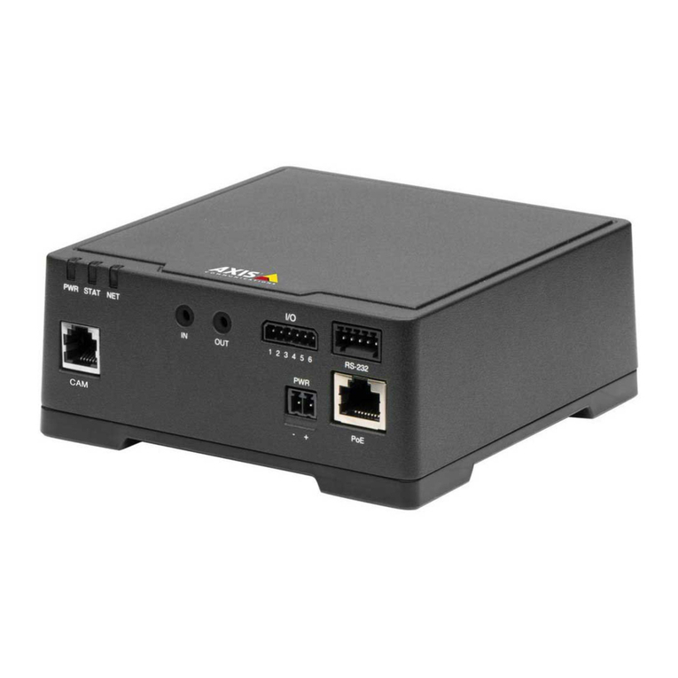
Simon S82 User manual

Lector biométrico en red S82
Network biometric reader S82 Art. 8902009-039
Alimentación:
Consumo Máx (±5%):
Capacidad de huellas:
Comunicación:
Distancia del cable:
Lector de huellas:
1:1000 tiempo de
respuesta:
Seguridad:
Temperatura de uso:
Humedad:
Dimensiones (mm):
Protección:
Personalizable:
Power supply :
Max Consumption(±5%):
Fingerprint capacity:
Interface:
Cable distance:
Fingerprint Sensor Type:
1:1000 identication
time:
Security:
Operating Temperatures:
Humidity:
Dimensions (mm):
Protection standard:
Customizable:
9-14Vdc
100mA
Hasta 100 huellas.
Wiegand 8 to 128 bits; Por defecto:
Wiegand 26bit
50m
Capacitativo
970 msec, incluido tiempo de extracción
de características
Tamper antisabotaje
-20ºC a +50ºC
5% a 93% HR sin condensación
72x72x45
IP40
Simon 82 Detail, Simon 82 y 82 Nature
9-14Vdc
100mA
Up to 100 prints.
Wiegand 8 to 128 bits; Default: Wiegand
26bit
50m
Swipe Capacitive
970 msec, including feature extraction
time
Tamper
-20ºC a +50ºC
5% to 93% RH without condensation
72x72x45
IP40
Simon 82 Detail, Simon 82 and 82 Nature
Conexión con un lector de
tarjetas o teclado adicional
Connection to additional card
reader or keypad
Central Controladora
Access Control
Art. 8902013-039
990826 17-05-2016
SIMON, S.A. Diputación, 390-392 / 08013 Barcelona
Art. 8900071- 030/038/093
Tamper
12 V DC
LG- LEDs
RS485
WIEGAND
LR-
B
A
D1
D0
GND
12V DC 9-14V DC 9-14V DC
GND Tierra Ground
ARS485 A RS485 A
BRS485 B RS485 B
LR- LED Rojo - Red LED -
LG- LED Verde - Green LED -
D1 Datos 1 Data 1
D0 Datos 0 Data 0
Tamper Interruptor antisabotaje(NO) Tamper Switch NO
Tamper Interruptor antisabotaje(NO) Tamper Switch NO
ES
Cableado / Wiring
Conexión / Connection
Montaje / Mounting
1 2 3
www.simon.es
EN
Amarillo / Yellow
Blanco / White
Rojo / Red
Negro / Black
Naranja / Orange
Verde / Green
Max 50 m
12V dc Ac. Granted LED
Ac. Denied LED
D1
A
Led Green -
Led Red -
GND
GND
12V Out
D0
D0
D1
RS 845 A
RS 845 B
B

Conectar el Lector biométrico en red S82 con el Teclado en red S82 o
con Lector de tarjetas en red S82
Connecting Network Biometric reader S82 with Network Keypad S82 or
with Network proximity reader S82
Central Controladora
Access Control
Art. 8902013-039
Lector Biométrico en red
Network biometric reader
Art. 8902009-039
Teclado en red
Network keypad
Art. 8902011-039
Lector de tarjeta en red
Network proximity reader
Art. 8902010-039
1
www.simon.es
Amarillo / Yellow
Blanco / White
Rojo / Red
Negro / Black
Naranja / Orange
Verde / Green
Max 50 m
12V dc Ac. Granted LED
Ac. Denied LED
D1
A
Led Green -
Led Red -
GND
GND
12V Out
D0
D0
D1
RS 845 A
RS 845 B
B
1. Conectar los dos lectores con el cable suministrado.
Connect both devices with the cable provided.
2. Conectar el lector biométrico en red S82 (Art. 8902009-039) a la central controladora (Art. 8902013-039).
El Lector de tarjetas en red S82 (Art. 8902010-039) o el teclado en red S82 (Art. 8902011-039)no esta conectado a la controladora.
Connect the network Biometric readerS82 (Art. 8902009-039) to the Access Control (Art. 8902013-039).
The Network proximity reader S82 (Art. 8902010-039) or the network Keypad S82 (Art. 8902011-039) is not connected to the controllerr.
3a. En las propiedades del lector en el software, para el tipo de lector
seleccione BIO 8902009-039 + RFID 8902010-039
In the software, in reader’s properties, for type of reader select
BIO 8902009-039 + RFID 8902010-039
3.b En las propiedades del lector en el software, para el tipo de lector
seleccione BIO 8902009-039 + Teclado 8902011-039
In the software, in reader’s properties, for type of reader select
BIO 8902009-039 + Teclado 8902011-039
4.b Poner en marchar el teclado como lector esclavo.
Put the keypad to work as slave unit.
Pulsar B+000000Press B+000000
Pulsar 0 Press 0
Pulsar 2 Press 2
Pulsar A para salir Press A to exit

Conexión de lectores biométricos a la central controladora
Connecting biometric readers to controller
www.simon.es
2
- Las líneas D0 y D1 son las líneas Wiegand y el número Wiegand se
envía a través de ellas.
- La línea RS485 (A, B) se usa para la conguración de transferencia
de huellas dactilares y del lector.
- Los lectores biométricos deben recibir la energía del controlador.
- Si usa otro suministro de energía para el lector biométrico, conecte
la toma de tierra (Gnd) de ambos dispositivos para asegurar la trans-
ferencia correcta de la señal Wiegand.
- Cuando haya conectado el lector y lo haya encendido, el LED parpa-
deará en naranja y emitirá dos pitidos. Esto indica que está encendido
y listo para su uso.
- El registro de la huella dactilar se realiza desde el software del orde-
nador. Se debe establecer la conexión entre los lectores biométricos
y el ordenador.
CONEXIÓN DE LECTORES BIOMÉTRICOS EN LA MISMA LÍNEA
RS485 CON LAS CENTRALES CONTROLADORAS (Art. 8902013-039)
- Los lectores biométricos se conectan a través del bus RS485, el mismo al
que están conectados los controladores EWS.
- El número máximo de unidades en una red (EWS + lectores biométricos)
es de 32.
- Si hay más de 32 unidades en una red, use un concentrador RS485 para
conectarlas.
- La línea RS485 se debe congurar en forma de cadena tipo margarita,
NO en forma de estrella. Si se debe usar una estrella en algunos puntos,
mantenga estas conexiones fragmentadas lo más cerca posible de la línea
central RS485. La longitud máxima de la conexión fragmentada depende
de la instalación (número total de dispositivos en la línea RS485, longitud
total del cable, terminación, tipo de cable...), por lo que se recomienda que
las conexiones fragmentadas tengan menos de 10 metros de longitud.
Recuerde que esto puede causar errores de comunicación con el software
del ordenador.
- El cable debe ser trenzado y apantallado, con una sección transversal
mínima de 0,5 mm .
- Conecte el hilo de tierra (0 V) de cada unidad a la línea RS485 usando un
tercer alambre en el mismo cable.
- La pantalla del cable de comunicación entre dos dispositivos se debe
conectar a TIERRA desde UN lateral de la línea RS485. Use el lateral que
tiene conexión a tierra para crear una red de toma de tierra.
TCP/IP GND GND
RS485
Máx. 5m
Max. 5m
1 km máx./ 32 Unidades (Centrales controladoras+ lectores
biométricos)
1 km max / 32 Units (Access controls+biometric readers)
Ponga el puente (120 ohm) en posición cerrada en la primera
y la última central controladora de la red RS485
Put the jumper (120ohm) in closed position onthe rst and the last
controller on a RS485 network
RS485
PC
- The lines D0 and D1 are the Wiegand lines and the Wiegand
Number is sent through them.
- The RS485 line (A, B) is used for ngerprint transfer and reader
settings.
- The Biometric readers must be powered from the controller.
- If you use different power supply for the biometric reader,
connect the GND from the both devices to ensure correct transfer
of the wiegand signal
- When you have connected the reader and powered on, the LED
should ash in orange light + 2 beeps. This lets you know it’s on
and ready for use.
- Fingerprint enrollment is done from the PC Software.
Connection between the Biometric readers and the PC must be
established.
CONNECTING BIOMETRIC READERS IN SAME RS485
LINE WITH THE CONTROLLERS (Art. 8902013-039)
- The Biometric readers are connected through RS485 bus. The same
RS485 bus that the EWS controllers are connected to.
- Maximum units in one network (EWS + Biometric readers) is 32.
- If there are more than 32 units in one network, please utilize RS 485
HUB to connect.
- The RS485 Line should be congured in the form of a daisy chain,
NOT in a form of a star. If star must be used in some points, keep
the stubs from the RS485 backbone as short as possible. Maximum
length of the stub is dependant of the installation (total number of
devices in RS485 line (total cable length, termination, cable type...)
so recommendation is to keep stubs shorter than 5 meters, keeping
in mind that this can be possible reason for errors in communication
with PC software
- The cable must be twisted and shielded with a min. 0.2 mm2 cross
section.
- Connect the ground (0V) of each unit in the RS 485 Line using a
third wire in the same cable.
- The shield of the communication cable between two devices must be
connected to the EARTH from ONE side of the RS 485 Line.Use the
side that has earth connection to the building’s grounding network.
L
R55
C41
L2
R36
R18
R25
R24
R10
C34
L10
L11
C18
C33
R9
C42
C1
R5
R45
C43
C44
R28
R21
C45
D13
L
R46
C3
C5
R38
L
R14
ZD4 C32
R19
R37
C27
L6
C16
C15
RX4
D5
D10
R32 R33 R35
R49
IC6
ZD5
ZD6
R22
L3
R53
R34
TAS1
IC11
R15
IC15
R3
R4
L8
R47
FUSE1
IC8
R20
R16
R11
C2
X1
C4
IC7 ICN2
R1
C13
C12
ICN1
R23
R48
A
LD5
RE1 RE3
A
LD8
X3
IC1
C6
U5
L5
L4
RE4RE2
A
LD6 A
LD9
L
R13
ZD1
R54
R50
6
IC12 R17
7
R62
D3
D2
RX3
R2
LD21
IC2 R30
BAT
U1
IC5
FUSE2
IC3
A
IC1
A
A
A
A
Free Led 1
Free Led 2
GND
12V out
D0
D1
Free Led 1
Free Led 2
GND
12V out
D0
D1
Door Sensor2
Door Sensor1
Exit Button1
Exit Button2
GND
GND
Free In 2 -
Free In 2 +
Free In 1 -
Free In 1 +
Rx Tx Busy 12V 5V 3.3V
System
OK
Door 1 Door 2
Free Out 1 Free Out 2
TCP/IP Earth
12Vdc Out
L
R55
C41
L2
R36
R18
R25
R24
R10
C34
L10
L11
C18
C33
R9
C42
C1
R5
R45
C43
C44
R28
R21
C45
D13
L
R46
C3
C5
R38
L
R14
ZD4 C32
R19
R37
C27
L6
C16
C15
RX4
D5
D10
R32 R33 R35
R49
IC6
ZD5
ZD6
R22
L3
R53
R34
TAS1
IC11
R15
IC15
R3
R4
L8
R47
FUSE1
IC8
R20
R16
R11
C2
X1
C4
IC7 ICN2
R1
C13
C12
ICN1
R23
R48
A
LD5
RE1 RE3
A
LD8
X3
IC1
C6
U5
L5
L4
RE4RE2
A
LD6 A
LD9
L
R13
ZD1
R54
R50
6
IC12 R17
7
R62
D3
D2
RX3
R2
LD21
IC2 R30
BAT
U1
IC5
FUSE2
IC3
A
IC1
A
A
A
A
Free Led 1
Free Led 2
GND
12V out
D0
D1
Free Led 1
Free Led 2
GND
12V out
D0
D1
Door Sensor2
Door Sensor1
Exit Button1
Exit Button2
GND
GND
Free In 2 -
Free In 2 +
Free In 1 -
Free In 1 +
Rx Tx Busy 12V 5V 3.3V
System
OK
Door 1 Door 2
Free Out 1 Free Out 2
TCP/IP Earth
12Vdc Out
50 ohm 50 ohm

3
- Cuando todos los controles están conectados a través de TCP/IP,
entonces la red Rs485 se convierte en local (del Lector 1 al Contro-
lador y luego al Lector 2).
- Conecte los lectores directamente a los terminales Rs485 en cada
controlador.
- Si la distancia Lector-Controlador es grande (50 metros) y si no se
puede establecer la comunicación con el lector, entonces termine la
red Rs485 cerrando el puente en el Controlador EWS
NOTA: Esta conguración se recomienda cuando tienes multi-
ples lectores biométricos en la misma red. En esta congura-
ción, NO ES NECESARIO resistencias.
Cuando todo las centrales tienen comunicación TCP/IP con los
lectores biométricos son fáciles de cablear. Cuando las centrales
tienen comunicación RS485, es difícil mantener la cadena deseada
en la red RS485. Cablear los lectores biométricos de esta forma es
un reto. Vea el esquema siguiente.
CONEXIÓN DE LECTORES BIOMÉTRICOS CUANDO TODOS
LOS CONTROLADORES TIENEN COMUNICACIÓN TCP/IP
CONNECTING BIOMETRIC READERS WHEN ALL THE
CONTROLLERS HAVE TCP/IP COMMUNICATION
- When all the controllers are connected via TCP/IP, then the RS485
network becomes local (from Reader 1 to the Controller then
to the Reader 2).
- Connect the readers directly to the Rs485 terminals in each
controller.
- If the distance Reader-Controller is high (50meters) and if the
communication with the reader can not be established, then
terminate the RS485 network by closing the jumper in the EWS
Controller
NOTE: This is recommended conguration when you have
multiple biometric readers in the same network. In this
conguration, NO TERMINATION resistors are required.
When all the controllers have TCP/IP communication the biometric
readers are easily wired. When the controllers have RS485
communication, it is difcult to maintain the daisy chain of the RS485
network. Wiring the biometric readers in that formation is a challenge.
See the schematic diagram bellow.
www.simon.es
L
R55
C41
L2
R36
R18
R25
R24
R10
C34
L10
L11
C18
C33
R9
C42
C1
R5
R45
C43
C44
R28
R21
C45
D13
L
R46
C3
C5
R38
L
R14
ZD4 C32
R19
R37
C27
L6
C16
C15
RX4
D5
D10
R32 R33 R35
R49
IC6
ZD5
ZD6
R22
L3
R53
R34
TAS1
IC11
R15
IC15
R3
R4
L8
R47
FUSE1
IC8
R20
R16
R11
C2
X1
C4
IC7 ICN2
R1
C13
C12
ICN1
R23
R48
A
LD5
RE1 RE3
A
LD8
X3
IC1
C6
U5
L5
L4
RE4RE2
A
LD6
A
LD9
L
R13
ZD1
R54
R50
6
IC12 R17
7
R62
D3
D2
RX3
R2
LD21
IC2 R30
BAT
U1
IC5
FUSE2
IC3
A
IC1
A
A
A
A
Free Led 1
Free Led 2
GND
12V out
D0
D1
Free Led 1
Free Led 2
GND
12V out
D0
D1
Door Sensor2
Door Sensor1
Exit Button1
Exit Button2
GND
GND
Free In 2 -
Free In 2 +
Free In 1 -
Free In 1 +
Rx Tx Busy 12V 5V 3.3V
System
OK
Door 1 Door 2
Free Out 1 Free Out 2
TCP/IP Earth
12Vdc Out
RS485
PC TCP/IP
Switch
Máx. 50m
Max. 50m
L
R55
C41
L2
R36
R18
R25
R24
R10
C34
L10
L11
C18
C33
R9
C42
C1
R5
R45
C43
C44
R28
R21
C45
D13
L
R46
C3
C5
R38
L
R14
ZD4 C32
R19
R37
C27
L6
C16
C15
RX4
D5
D10
R32 R33 R35
R49
IC6
ZD5
ZD6
R22
L3
R53
R34
TAS1
IC11
R15
IC15
R3
R4
L8
R47
FUSE1
IC8
R20
R16
R11
C2
X1
C4
IC7 ICN2
R1
C13
C12
ICN1
R23
R48
A
LD5
RE1 RE3
A
LD8
X3
IC1
C6
U5
L5
L4
RE4RE2
A
LD6 A
LD9
L
R13
ZD1
R54
R50
6
IC12 R17
7
R62
D3
D2
RX3
R2
LD21
IC2 R30
BAT
U1
IC5
FUSE2
IC3
A
IC1
A
A
A
A
Free Led 1
Free Led 2
GND
12V out
D0
D1
Free Led 1
Free Led 2
GND
12V out
D0
D1
Door Sensor2
Door Sensor1
Exit Button1
Exit Button2
GND
GND
Free In 2 -
Free In 2 +
Free In 1 -
Free In 1 +
Rx Tx Busy 12V 5V 3.3V
System
OK
Door 1 Door 2
Free Out 1 Free Out 2
TCP/IP Earth
12Vdc Out
L
R55
C41
L2
R36
R18
R25
R24
R10
C34
L10
L11
C18
C33
R9
C42
C1
R5
R45
C43
C44
R28
R21
C45
D13
L
R46
C3
C5
R38
L
R14
ZD4 C32
R19
R37
C27
L6
C16
C15
RX4
D5
D10
R32 R33 R35
R49
IC6
ZD5
ZD6
R22
L3
R53
R34
TAS1
IC11
R15
IC15
R3
R4
L8
R47
FUSE1
IC8
R20
R16
R11
C2
X1
C4
IC7 ICN2
R1
C13
C12
ICN1
R23
R48
A
LD5
RE1 RE3
A
LD8
X3
IC1
C6
U5
L5
L4
RE4RE2
A
LD6 A
LD9
L
R13
ZD1
R54
R50
6
IC12 R17
7
R62
D3
D2
RX3
R2
LD21
IC2 R30
BAT
U1
IC5
FUSE2
IC3
A
IC1
A
A
A
A
Free Led 1
Free Led 2
GND
12V out
D0
D1
Free Led 1
Free Led 2
GND
12V out
D0
D1
Door Sensor2
Door Sensor1
Exit Button1
Exit Button2
GND
GND
Free In 2 -
Free In 2 +
Free In 1 -
Free In 1 +
Rx Tx Busy 12V 5V 3.3V
System
OK
Door 1 Door 2
Free Out 1 Free Out 2
TCP/IP Earth
12Vdc Out

AJUSTE DE RS485 RS485 TUNING
www.simon.es
4
Resistencias de la terminación RS485:
- Termine ambos extremos de la línea con una resistencia de 120
Ohm. Si el extremo de la línea es la central controladora, utilice
una resistencia integrada (120 ohmios) cerrando el puente.
- Si no se establece la comunicación de manera estable, utilice las
resistencias externas suministradas con el kit de hardware.
Al usar un cable compatible con CAT 5, en la mayoría de los casos
la solución podría ser una terminación hecha con una resistencia
externa de 50 Ohm o con una combinación de una resistencia
externa de 50 Ohm y la resistencia de la terminación de la central
controladora (120 Ohm).
Siga estas instrucciones para deslizar el dedo correctamente. Coloque
el dedo seleccionado, desde la primera articulación, sobre el sensor
de deslizamiento y muévalo de manera uniforme hacia usted con un
movimiento constante.
- Deslizamiento válido: El LED de estado tricolor se ilumina en verde +
pitido de OK (un pitido corto más uno largo)
- Deslizamiento o lectura incorrectos: El LED de estado tricolor se
ilumina en rojo + pitido de error (3 pitidos cortos)
RS485 Termination resistors:
- Terminate both ends of the line with 120 Ohm resistor. If end of line
is controller, use built in resistor (120 ohm) by closing the jumper.
- If the communication is not established and stable, use the external
resistors provided in the hardware kit.
When using CAT 5 compatible cable, in most of the cases,
termination made with 50 Ohm external resistor or combinationof 50
Ohm external and termination resistor from the controller (120 Ohm)
should be the solution.
Follow the below instructions for correct nger swiping
Starting from the rst nger joint, place the selected nger on the swipe
sensor and move it evenly towards oneself in one steady movement.
- For a valid swipe: Tricolour Status LED turns green + OK Beep(short +
long beep)
- For an invalid or misread swipe: Tricolour Status LED turns red +
Error Beep ( 3 short beeps)
Deslizamiento recomendado / Recommended Swiping
1 km máx./ 32 Unidades (Centrales
controladoras+ lectores
biométricos)
1 km max / 32 Units (Access
controls+biometric readers)
Ponga el puente (120 ohm) en posición cerrada en la primera
y la última central controladora de la red RS485
Put the jumper (120ohm) in closed position onthe rst and the last
controller on a RS485 network
TCP/IP GND GND
RS485
Máx. 5m
Max. 5m
RS485
PC
L
R55
C41
L2
R36
R18
R25
R24
R10
C34
L10
L11
C18
C33
R9
C42
C1
R5
R45
C43
C44
R28
R21
C45
D13
L
R46
C3
C5
R38
L
R14
ZD4 C32
R19
R37
C27
L6
C16
C15
RX4
D5
D10
R32 R33 R35
R49
IC6
ZD5
ZD6
R22
L3
R53
R34
TAS1
IC11
R15
IC15
R3
R4
L8
R47
FUSE1
IC8
R20
R16
R11
C2
X1
C4
IC7 ICN2
R1
C13
C12
ICN1
R23
R48
A
LD5
RE1 RE3
A
LD8
X3
IC1
C6
U5
L5
L4
RE4RE2
A
LD6 A
LD9
L
R13
ZD1
R54
R50
6
IC12 R17
7
R62
D3
D2
RX3
R2
LD21
IC2 R30
BAT
U1
IC5
FUSE2
IC3
A
IC1
A
A
A
A
Free Led 1
Free Led 2
GND
12V out
D0
D1
Free Led 1
Free Led 2
GND
12V out
D0
D1
Door Sensor2
Door Sensor1
Exit Button1
Exit Button2
GND
GND
Free In 2 -
Free In 2 +
Free In 1 -
Free In 1 +
Rx Tx Busy 12V 5V 3.3V
System
OK
Door 1 Door 2
Free Out 1 Free Out 2
TCP/IP Earth
12Vdc Out
L
R55
C41
L2
R36
R18
R25
R24
R10
C34
L10
L11
C18
C33
R9
C42
C1
R5
R45
C43
C44
R28
R21
C45
D13
L
R46
C3
C5
R38
L
R14
ZD4 C32
R19
R37
C27
L6
C16
C15
RX4
D5
D10
R32 R33 R35
R49
IC6
ZD5
ZD6
R22
L3
R53
R34
TAS1
IC11
R15
IC15
R3
R4
L8
R47
FUSE1
IC8
R20
R16
R11
C2
X1
C4
IC7 ICN2
R1
C13
C12
ICN1
R23
R48
A
LD5
RE1 RE3
A
LD8
X3
IC1
C6
U5
L5
L4
RE4RE2
A
LD6 A
LD9
L
R13
ZD1
R54
R50
6
IC12 R17
7
R62
D3
D2
RX3
R2
LD21
IC2 R30
BAT
U1
IC5
FUSE2
IC3
A
IC1
A
A
A
A
Free Led 1
Free Led 2
GND
12V out
D0
D1
Free Led 1
Free Led 2
GND
12V out
D0
D1
Door Sensor2
Door Sensor1
Exit Button1
Exit Button2
GND
GND
Free In 2 -
Free In 2 +
Free In 1 -
Free In 1 +
Rx Tx Busy 12V 5V 3.3V
System
OK
Door 1 Door 2
Free Out 1 Free Out 2
TCP/IP Earth
12Vdc Out
50 ohm 50 ohm

Conguración de lectores biométricos en el software SIMON accesos
Conguring the biometric readers in SIMON accesos software
5
AÑADIR UN LECTOR BIOMÉTRICO
1. Amplíe el elemento Puerta para ver los lectores
2. Haga clic con el botón derecho sobre el lector y seleccione las
propiedades (1)
3. En la pestaña Básicas, para “Tipo” de Lector seleccione “BIO
8902009-039”. (2)
4. Tras seleccionar el tipo, aparecerá una tercera pestaña:
“Biométrico”.
Vaya a esa pestaña e introduzca el número de serie del Lector
Biométrico. (3)
Nota importante: El número de serie del lector gura en un adhesivo
en el interior del lector, en la caja de embalaje y se puede encontrar
desde el software (haga clic con el botón derecho sobre el portal/bus-
car dispositivos/lectores). (4 y 5)
Para comprobar si el lector está En Línea, haga clic con el botón de-
recho sobre el lector y seleccione “Comprobar versión”. En la ventana
Eventos debe aparecer el mensaje “Dispositivo EN Línea, Tipo: BIO
8902009-039” (6)
ADDING BIOMETRIC READER
1. Expand the Door item to view the readers
2. Right click on the reader and select properties (1)
3. In the Basic tab, for “Type” of the Reader select “BIO
8902009-039”. (2)
4. After selecting the type, a third tab will appear “Biometric”. Go to
that tab and put the serial number of the Biometric Reader. (3)
Important Note: The serial number of the reader can be found on
a sticker inside the reader, on the packaging box and it can be
search from the software (right click on the portal/search devices/
readers). (4 & 5)
To check if the reader is On Line, right click on the reader and
select “Check version”. In the Event Window a message should
appear “Device ON Line, Type: BIO 8902009-039” (6)
www.simon.es
1
3
5
6
4
2

6
1. Abra la ventana Usuarios y cree un nuevo usuario. Haga clic en
“Nuevo usuario”, ponga un nombre y ID (número de tarjeta)(7)
2. Vaya a la pestaña “Biométrico”
3. Seleccione el lector (haga clic con el botón izquierdo) desde el
cual se va a efectuar el registro. (8)
4. Haga clic con el botón derecho sobre la punta del dedo y seleccio-
ne registrar. (9)
5. En los 25 segundos siguientes, pase el dedo sobre
el lector seleccionado un mínimo de 5 veces y la
punta del dedo se pondrá en rojo. (10). Durante
estos 25 segundos, el lector estará parpadeando
continuamente en naranja.
6. Repita los puntos 4 y 5 por cada dedo que desee registrar.
7. Haga clic en “Guardar nuevo” y la huella dactilar se enviará auto-
máticamente a todos los lectores biométricos a los que tenga acceso
ese usuario, es decir, a todos los lectores según el nivel de acceso
asignado a ese usuario.
Ejemplo:
Si el usuario tiene un nivel de acceso “Ilimitado”, entonces las
huellas dactilares se enviarán a todos los lectores; si el usuario tiene
un nivel de acceso sólo para el Lector 1 y el Lector 3, entonces las
huellas dactilares se enviarán sólo a esos dos lectores.
Nota: Para comprobar si se envían al lector todas las huellas dactila-
res, haga clic con el botón derecho sobre el lector y seleccione
“Estado de la memoria”. (11)
En la ventana de eventos aparecerá una línea indicando el número
de huellas dactilares almacenadas en el lector. (12)
Nota: Si se añaden más huellas dactilares para un mismo usuario,
todas ellas enviarán el mismo código de Wiegand al controlador, el
escrito en el campo Id. de usuario (número de tarjeta).
REGISTRO DE HUELLAS DACTILARES DESDE UN LECTOR ENROLLING FINGERPRINTS FROM A READER
1. Open the Users Window and create a new user. Click on “New
User”, put a name and ID(card number). (7)
2. Go to the “Biometric” Tab
3. Select the reader(with left click) from which the enrollment will be
done. (8)
4. Right click on the ngertip and select enroll. (9)
5. In the next 25 sec. swipe the nger on
the selected reader min. 5 times and
the nger tip will turn red. (10). In these
25 sec. the reader will continuously blink in
orange.
6. Repeat point 4&5 for each nger that should be enrolled.
7. Click on “Save New” and the ngerprint will be sent automatically
to all Biometric Readers where that user has access, i.e. to all the
readers according to the Access Level assign to that user.
Example
If the user has “Unlimited” Access level then the ngerprints will be
sent to all readers, if the user has Access level only for Reader1 and
Reader 3 then the ngerprints will be sent only to those two readers.
Note:
To check if all the ngerprints are sent to the reader, right click on the
reader and select “Memory Status”. (11)
In the event window a line will appear indicating the number of
ngerprints stored in the reader. (12)
Note:
If more ngerprints are added for one user, all ngerprints will send the
same Wiegand Code to the controller, the one written in the eld User
ID(card Number).
www.simon.es
x5
x5
7
10
11
9
8
12

7
En general, las huellas dactilares se almacenan en el lector
biométrico y en el software. El borrado sólo se puede efectuar en los
lectores o desde ambos lugares.
Borrado de un solo usuario desde el lector biométrico
Seleccione el Usuario
Haga clic en “Eliminar usuario”. El Usuario, junto con sus huellas
dactilares, se borrará del software y de los lectores de huellas
dactilares. (13)
Borrado de todos los usuarios del lector biométrico
Haga clic con el botón derecho sobre el lector y seleccione “Eliminar
todos los usuarios del lector” (14)
Borrar una o varias huellas dactilares
Seleccione el Usuario y abra la pestaña “Biométrico”
Vaya a la huella dactilar que desee borrar, haga clic con el botón
derecho y seleccione “Eliminar” para un solo dedo o “Eliminar todo”
para todos los dedos del Usuario.
Haga clic en “Guardar cambios”.
Con este procedimiento las huellas dactilares del Usuario se borra-
rán del software y del lector. (15)
CARGA DE LAS HUELLAS DACTILARES EN LOS LECTORES
BIOMÉTRICOS
Haga clic con el botón derecho sobre el lector biométrico
Seleccione “Cargar todos usuarios en el lector”(16)
Mientras recibe las huellas dactilares, el lector se pondrá intermiten-
te en naranja.
Nota: Utilice esta característica cuando cambie o añada un lector,
si se borran tareas pendientes en el software o si existen dudas
sobre si las huellas dactilares en la memoria del lector no se han sin-
cronizado con la base de datos del software. En el uso normal, las
huellas dactilares se envían automáticamente y esta característica
no se utiliza.
BORRADO DE HUELLAS DACTILARES DELETING FINGERPRINTS
In General, the ngerprints are stored in the Biometric reader and in
the Software. Deleting can be done only in the readers or from both
places.
Deleting one user from the biometric reader
Select the User
Click on “Delete User”. The User together with its ngerprints will be
deleted from both the software and the ngerprint readers. (13)
Deleting all users from the biometric reader
Right click on the reader and select “Delete all users from reader” (14)
Delete one or more ngerprints
Select the User and open the “Biometric” tab
Go to the ngertip that needs to be deleted, right click and select
”Delete” for one nger or “Delete All” for all ngers of the User.
Click “Save Changes”.
With this procedure the User’s ngerprints are deleted from the
software and from the reader. (15)
UPLOADING THE FINGERPRINTS TO THE BIOMETRIC
READERS
Right click on the biometric reader
Select “Upload all users to reader”(16)
While receiving the ngerprints the reader will blink in orange.
Note: Use this feature when you change or add a reader, if
pending tasks are deleted in the software or if there are doubts
that ngerprints in the reader memory are not synchronized with
the software database. In normal usage, the ngerprints are sent
automatically and this feature is not used.
15 16
13
14
www.simon.eswww.simon.es

8
ACTUALIZACIÓN DE FIRMWARE
Haga clic con el botón derecho sobre el lector y seleccione el
menú Actualización de rmware(17)
En la ventana Actualización de rmware, haga clic en el botón
Examinar (18). La ubicación por defecto de los archivos de
rmware instalados con PROS CS es la carpeta “Firmware”.
Seleccione el archivo de rmware con una extensión “xhc”.
Haga clic en el botón Cargar.
Importante: Espere al mensaje de nalización de carga. Durante
todo el proceso, no apague el lector, el software ni ningún disposi-
tivo de comunicación entre ellos.
CARGAR LA CONFIGURACION EN UN LECTOR
· Haga clic con el botón derecho en el lector y seleccione el menú
Enviar conguración. (19)
· Consulte el panel de eventos para comprobar el ujo de la conguración.
Nota: El lector biométrico obtiene su conguración automáticamente.
Esta función se utiliza si el lector está fuera de línea al hacer los cambios.
CONFIGURACIONES AVANZADAS
Enviar este Id. para:
Huella desconocida envía la Wiegand deseada cuando se
aplica una huella desconocida.
Luz de fondo:
Luz de fondo del dispositivo (ENCENDIDA o APAGADA)
Timbre:
Timbre del dispositivo (ENCENDIDO o APAGADO)
Flexibilidad de aceptación de la huella:
Tolerancia aceptada. El valor recomendado es “Automático (seguro)”.
FIRMWARE UPDATE
Right-click on the reader and select Firmware update menu (17)
On the Firmware update window, click on the Browse button (18).
The default location of the rmware les installed with PROS CS
is in the folder “Firmware”.
Select the rmware le with a “xhc” extension.
Click on the Upload button
Important: Wait for the update end message. Do not turn off the
reader, the software or any communication device in between
during the entire process.
SEND CONFIGURATION
· Right-click on the reader and select the Send conguration menu (19)
· See the events panel to check the conguration ow
Note: The biometric reader gets its settings automatically. This
function is used if the reader was off line while making the changes.
ADVANCED SETTINGS
Send This ID for:
Unknown Finger sends the desired Wiegand when an unknown
nger is applied. (20)
Backlight:
Backlight of the device (ON or OFF)
Buzzer:
Buzzer of the device (ON or OFF)
Finger Acceptance Flexibility:
Accepted tolerance. The recommended value is “Automatic Secure”.
www.simon.es
19
17
18
20

9
SIMON ACCESOS ha denido Wiegand de 26, 30, 34 y de 40
bits como opciones estándar y deja 3 conguraciones Wiegand
como denibles por el usuario
Para congurar el formato wiegand personalizado seleccione el
menú Wiegand en Conguración (21)
En la ventana de conguración de wiegand selecciones uno de
los wiegand personalizados (22)
Establezca los parámetros wiegand (23)
Haga clic en el botón Guardar
Nota: Los ajustes Wiegand no están al alcance el usuario nal
común. Pida a su instalador que establezca los parámetros y no
los cambie después.
WIEGAND PERSONALIZADA CUSTOM WIEGAND
SIMON ACCESOS has dened Wiegand 26, 30, 34, 40 bit as
standard options and other 3 Wiegand settings as user denable.
To setup custom Wiegand format Select Wiegand menu from
Settings (21)
At Wiegand setup window select one from customs Wiegand (22)
Set Wiegand parameter (23)
Click on Save button
Note: Wiegand settings are out of scope for common end user. Please
ask your installer to set the parameters and do not change it later.
21
23
22
www.simon.eswww.simon.es

Descripción del protocolo Wiegand / Wiegand protocol description
Descripción del protocolo Wiegand / Wiegand protocol description
www.simon.es
10
Los datos se envían a través de las líneas DATA 0 para el “0” lógico
y DATA 1 para el “1” lógico. Ambas líneas usan lógica inversa, lo que
signica que un pulso bajo en DATA 0 indica un “0” y un pulso bajo
en DATA 1 indica un “1”. Cuando las líneas están altas, no se envía
ningún dato. Solo 1 de las 2 líneas (DATA 0/DATA 1) puede pulsar al
mismo tiempo.
Ejemplo: datos 0010...
Bit de datos 0 = aproximadamente 100 μs (microsegundos)
Bit de datos 1 = aproximadamente 100 μs (microsegundos)
Tiempo entre dos bits de datos: aproximadamente 1 ms (milisegun-
do). Ambas líneas de datos (D0 y D1) están altas.
Descripción para el formato Wiegand de 26 bits
Cada bloque de datos consta de un primer bit de paridad P1, un
encabezado jo de 8 bits, 16 bits de código de usuario y un 2º bit de
paridad P2. Se muestra un bloque de datos como este a continuación:
Nota: Los bits de paridad se calculan de la siguiente manera:
P1 = la paridad par se calcula sobre los bits del 2 al 13 (X)
P2 = la paridad impar se calcula sobre los bits del 14 al 25 (Y)
Bit de paridad (bit 1) + Encabezado de 8 bits + Código de usuario de 16 bits = 2 bytes + Bit de paridad (bit 26)
Parity bit (bit 1) + 8 bits header + 16 bits user code = 2 bytes + Parity bit (bit 26)
P1 XXXXXXXX XXXXYYYY YYYYYYYY P2
Ejemplo:
Example:
170 31527
1 1 0 1 0 1 0 1 0 0 1 1 1 1 0 1 1 0 0 1 0 0 1 1 1 0
No instale el dispositivo en un lugar expuesto a la luz del sol sin una
funda protectora.
No instale el dispositivo y el cableado cerca de una fuente fuerte de
campos electromagnéticos, como una antena de radiotransmisión.
No coloque el dispositivo cerca o encima de equipos de calefacción.
Cuando lo limpie, no lo haga con agua u otros productos de limpieza
líquidos, límpielo con un trapo o una toalla suave.
No permita que los niños toquen el dispositivo sin supervisión.
Tenga en cuenta que si el sensor se limpia con detergente, benceno
o disolvente, se dañará la supercie y no se podrán introducir
huellas dactilares.
The data is sent over the lines DATA 0 for the logic “0” and DATA
1 for the logic “1”. Both lines use inverted logic, meaning that a
pulse low on DATA 0 indicates a “0” and a pulse low on DATA 1
indicates a “1”.When the lines are high, no data is being sent.
Only 1 of the 2 lines ( DATA 0 / DATA 1 ) can pulse at the same
time.
Example: data 0010....
Data bit 0 = approximately 100 us (microseconds)
Data bit 1 = approximately 100 us (microseconds)
Time between two data bits: approximately 1 ms (millisecond).
Both data lines (D0 and D1) are high.
Description for the 26 bits Wiegand format
Each data block consists of a rst parity bit P1, a xed 8 bits
header, 16 bits of user code and a 2nd parity bit P2. Such a data
block is shown bellow:
Note: Parity bits are calculated as follows:
P1 = even parity calculated over the bits 2 to 13 (X)
P2 = odd parity calculated over the bits 14 to 25 (Y)
Do not install the device in a place subject to direct sun light
without protective cover.
Do not install the device and cabling close to a source of strong
electro-magnetic elds like radio-transmitting antenna.
Do not place the device near or above heating equipments.
If cleaning, do not spray or splash water or other cleaning liquids
but wipe it out with smooth cloth or towel.
Do not let children touch the device without supervision.
Note that if the sensor is cleaned by detergent, benzene or
thinner, the surface will be damaged and the ngerprint can’t be
entered.
D0
D1
0
0V
0V
5V
100 us
1 ms
5V 0 01
mê
F A A A A A A A A B B B B B B B B B
User codeSite code
Odd
Parity
Bit
Even
Parity
Bit
B B B B B B B O

www.simon.eswww.simon.es SIMON, S.A. Diputación, 390-392 / 08013 Barcelona
This manual suits for next models
1
Table of contents
Other Simon Switch manuals
