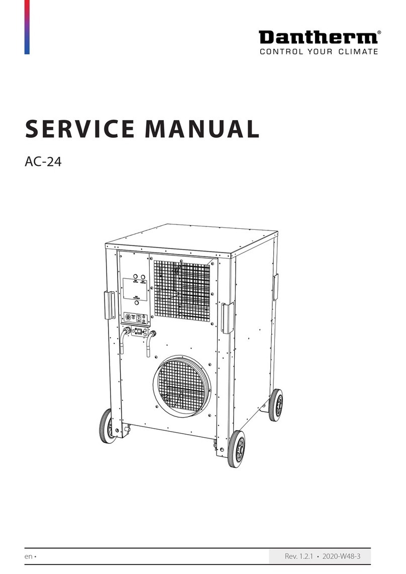
Dantherm 3000 User manual

1
081488•Version 1.0 17.09.2013
DC Air Conditioner 3000
Service manual
Rev. 1.0
en

2
Der tages forbehold for trykfejl og ændringer
Dantherm can accept no responsibility for possible errors and changes
Irrtümer und Änderungen vorbehalten
Dantherm n’assume aucune responsabilité pour erreurs et modifications éventuelles

3
081488•Version 1.0 17.09.2013
Introduction
Overview
Introduction
This is the service manual for the Dantherm DC Air Conditioner 3000.
Please see the below table of content for further information about the sections.
Manual
Part number of this service manual is 366245 and covers units with serial numbers from
1306121273752
Target group
The target group for this service manual are the technicians who install and maintain
the DC Air Conditioner 3000 unit, as well as the users of the unit.
Copyright
Copying of this service manual, or part of it, is forbidden without prior written permis-
sion from Dantherm Air Handling A/S.
Reservations
Dantherm reserves the right to make changes and improvements to the product and the
service manual at any time without prior notice or obligation.
Table of contents
This service manual covers the following main topics:
Introduction................................................................................................................3
Product description.....................................................................................................4
Overall description...............................................................................................4
Electronic control description ...............................................................................8
Connections.......................................................................................................11
Installation - outdoor.........................................................................................12
Installation –through wall ..................................................................................15
Service guide ............................................................................................................16
Preventive maintenance......................................................................................17
Troubleshooting ................................................................................................19
Electrical schematic............................................................................................21
Cooling circuit ...................................................................................................22
Spare part list ....................................................................................................24
Replacing parts ..................................................................................................25
Technical data ...................................................................................................28
Contact Dantherm..............................................................................................31

4
Product description
Overall description
Introduction
This section describes the overall product, and its functionality
Usage of the
DC Air Conditioner
3000
DC Air Conditioner 3000 is designed to control the internal temperature of an outdoor
enclosure. DC Air Conditioner 3000 removes dissipated heat from electronic equipment
and it´s designed to maintain correct temperature for electronic equipment.
Important
Dantherm Air Handling recommends that the cooling system should be running contin-
uously!
Section content
Product description.....................................................................................................4
Overall description...............................................................................................4
Electronic control description...............................................................................8
Connections ...................................................................................................... 11
Installation - outdoor......................................................................................... 12
Installation –through wall.................................................................................. 15

5
081488•Version 1.0 17.09.2013
Overall description, continued
Outdoor view
This illustrates the unit outdoor visible parts
Fig. 1
Parts description
outdoor view
This tables shows outdoor parts according to Fig. 1
Part
Function
1
Mounting frame
2
Lifting handles
3
Condenser air output
4
Condenser air input
5
Condensed water spigot
Continued overleaf

6
Overall description, continued
Indoor view
This illustrates the unit indoor visible parts
Fig. 2
Parts description
indoor view
This tables shows indoor parts according Fig. 2
Part
Function
1
Evaporator air inlet
2
Controller
3
Service entrance
4
Evaporator fan blowing cold air out
5
Serial number label
Continued overleaf

7
081488•Version 1.0 17.09.2013
Overall description, continued
Functionality
The illustration and table below show the airflows of DC Air Conditioner 3000.
The two air flows (internal/external) operate separately. External air is only used to cool
down the condenser which dissipates the heat absorbed by the indoor evaporator.
The air flows are not mixed
.
Fig. 3
Internal air flow
Warm, internal air is drawn into the unit by the internal evaporator fan, at the evapora-
tor opening, through the evaporator and the evaporator fan, and then released into the
enclosure through the evaporator fan opening.
External air flow
Cold, external air is drawn into the unit by the condenser fan, and routed through the
condenser, where it’s cooling down the condenser. After passing through the condenser
the air is returned to the external environment through the condenser fan.

8
Electronic control description
Introduction
This section describes key features of the electronic control, and how it operates.
WARNING
Never carry out any installation, maintenance or service, without disconnecting the DC
power supply, by means of the external power supply disconnecting devices.
Installation
requirements
Please incorporate the following when installing the electrical connections:
1. Any external supply should be protected, with an external disconnecting device
2. These disconnecting device, needs to be labelled, with rated voltage as well as
rated current
3. All cables, in a permanent installation, are imperative to install and secure
properly, to prevent any damage to equipment and/or humans.
Secure all cables with cable ties or appropriate cable fasteners, made for this
purpose.
Controller
Embedded controller
Controller
Functionallity
The control board controls fans and cooling compressor according to the temperature
in return air flow. The cooling capacity is automatically adjusted to match the present
heat dissipation from the affiliated applications, so the airconditioner always uses min-
imum energy according to heat load.
Phase
Description
1
When power is on, the evaporator fan will circulate the indoor air repeatedly
on idle speed.
2
When return air temperature reaches the predefined set point, internal fan
will speed up, the compressor will start on minimum rotation speed. In case
temperature keeps rising the compressor rotation speed will increase until a
balanced condition between the applied heat dissipation and cooling perfor-
mance has been obtained.
3
Temperature set point can adjusted in 5 fixed levels; 20℃-25℃-30℃-35℃-
40℃
4
If return air temperature drops below the hysteresis (set point –hysteresis),
the compressor will be stopped, the evaporator fan (internal fan) will keep
circulating internal air on idle speed, to prevent build-up of local hot spots.
5
Condenser fan speed is controlled according to condenser temperature to
keep acoustic noise level as low as possible.
6
Compressor has restart delay to protect the compressor against excessive
on/off cycling. Pre-set to 5 minutes.
Operating parameters can be adjusted to comply with specific operating conditions.
Continued overleaf

9
081488•Version 1.0 17.09.2013
Electronic control description, continued
Alarms
The controller has one hardware alarm output.
Alarm output is a bi-directional dry contact. Max load 60V/50mA. Contact is closed on
failure.
Two LED’s indicates status of operation.
LED indication
Color
STATUS
Definition
Green
On
Power supply OK
Off
No power or Voltage out of range
Flashing
Selftest on-going. See more at page 10
Red
Off
Normal operation
1 flash
Internal fan failure
3 flash
External fan failure
5 flash
Compressor failure
7 flash
Return air sensor failure
8 flash
Condenser sensor failure
9 flash
Compressor drive communication failure
10 flash
Low supply voltage
11 flash
High supply voltage
13 flash
HP/LP failure
15 flash
High temperature alarm
Data connection
Communication is possible between computer and the 9 pin D-SUB female.
Pin
Function
Illustration
1
NC
2
NC
3
TXD- (Z)
4
TXD+ (Y)
5
RXD+ (A)
6
NC
7
RXD- (B)
8
NC
9
NC
For service and test purpose, the communication line can be switched to terminal mode.
Can be used with PC and PuTTY terminal program, for change of operational settings
and monitoring during service.
Terminal use and adjustable parameters, described in separate document.
Continued overleaf
12345
6789

10
Electronic control description, continued
Data communication
The controller has an RS 485 communication line with an embedded ModBus protocol.
This interface has galvanic insulation.
Communication settings:
RS 485 specification
Baud rate
9600 baud
Bit
8 bit
Stop bit
1 bit
Parity
Non
Cooling setpoint
Cooling set point can be set between 20-40 °C in steps
of 5°C. with the set point dial on the front of the unit.
Reset and boot
By pressing the reset button for five seconds, the controller enters a reboot and test
phase
Step
Description
Eva.fan
Con.fan
Heater
Alarm
Comp.
Duration
1
OFF
Off
Off
Off
Off
Off
10s
2
Int.fan
On
(full speed)
Off
Off
Off
Off
30s
3
Ext.fan
On
(full speed)
On
(full speed)
Off
Off
Off
30s
4
Heater
On
(full speed)
On
(full speed)
On
Off
Off
10s
5
Alarm
On
(full speed)
On
(full speed)
On
On
Off
10s
6
Compressor
On
(full speed)
On
(full speed)
On
Off
On
45s
A duration of 2 minutes and 15 seconds in total.
f

11
081488•Version 1.0 17.09.2013
Connections
Connection
This illustration shows the control panel with connections.
Fig. 4
Connection
description
This describes the above connection:
Part
Function
1
Cooling set-point dial
2
Alarm output, see specification at page 9
3
RJ45 –factory only
4
Earth connection
5
Reset switch
6
Power input -44.0 to -58.0 VDC. Reverse polarity protected.
7
LED feedback, see specification at page 9

12
Installation - outdoor
Introduction
The unit can be mounted outdoor, flush to the wall, or through wall. Is through wall
please jump to next section in this manual
Flush wall outdoor
mounted
Mounting procedure for outside flush:
Step
Action
1
Unpack the unit, and locate the enclosed paper cutout template
2
Place and secure this paper template on the wall, at an appropriate location
and in correct level.
3
Draw up the inner cutout line, and mark the 16 pcs. Holes to be drilled
4
Cut with an appropriate tool the inner wall part away.
5
Drill the 16 pcs holes (8mm appropriate for the M6 holes in the unit frame)
Illustration:
Continued overleaf

13
081488•Version 1.0 17.09.2013
Installation - outdoor, continued
Flush mounted,
continued
Step
Action
7
After cutting apply a polymer sealing, at all four sides, following the outside
line of the drilled holes.
Illustration:
8
Lift and push the unit into the hole, and install all 16 pcs bolts
Continued overleaf

14
Installation - outdoor, continued
Flush mounted,
continued, continued
Step
Action
9
Install the drainage hose
10
Make electrical connection. Always install an external DC circuit breaker.
Illustration:
11
Connect additional connection to alarm out if needed, according the con-
nection section in this manual at page 11
Continued overleaf

15
081488•Version 1.0 17.09.2013
Installation –through wall
Throug wall
The through wall installation differs from outdoor only in two details:
Please read the guide for outdoor, and taking the below changes in consideration
Phase
Description
1
When marking the cutout area, don’t use the paper template.
Use instead a normal ruler, and mark a square of 480mm wide and 1260 mm
high according the dimension shown in the specification part of this manual
at page 29.
2
When unit is mounted from the inside, and pushed through the wall, seal
from the outside, all around the four edges.
Illustration:

16
Service guide
Overview
Introduction
This section gives all relevant information about servicing, spare parts and trouble
shooting.
Serial numbers
Product model and serial numbers are found on the nameplate.
Please have product model and serial numbers ready if you are contacting After Sales
Support.
Contents
This section covers the following topics:
Service guide ............................................................................................................16
Preventive maintenance......................................................................................17
Troubleshooting ................................................................................................19
Electrical schematic............................................................................................21
Cooling circuit ...................................................................................................22
Spare part list ....................................................................................................24
Replacing parts ..................................................................................................25
Technical data ...................................................................................................28

17
081488•Version 1.0 17.09.2013
Preventive maintenance
Introduction
Preventive maintenance has to be carried out to:
Anticipate a continues operation in product expected lifetime of 10 years or more
Meet the warranty conditions
Avoid malfunctions
Avoid inefficient operation
Maximize the unit’s lifetime
The factory warranty is only valid if documented preventive maintenance has been car-
ried out, with an time interval of:
Maximum 6 months when unit is located in normal air quality environment
Maximum 2 months when unit is located in bad quality air environment
A written log at site is adequate documentation for preventive maintenance.
Caution
Disconnect any supply before working on the unit
Make sure that all work has been performed correctly before switching power back
on
Cleaning
The unit must be cleaned according to the recommended preventive maintenance plan.
Tools required:
Vacuum cleaner or compressed air
Soft brush
TX20 screwdriver
NHR-60 cleaning agent if it´s very dirty
Phase
Description
1
Open the units outside cover
2
Clean the condenser
3
IF the coils still dirty, please apply NHR-60 cleaning agent on coil fins, and
after 5 minutes rinse gently with water, WITHOUT spraying water on any elec-
trical parts
4
Perform end inspection according inspection list below
Continued overleaf

18
Preventive maintenance, continued
Cooling circuit
The cooling circuit should only be serviced by trained cooling technicians.
The following steps is mandatory:
Step
Action
1
Check for any leakages in all junctions, with a suitable leakage detector foam.
2
Check the HP switch functionality.
A. After re-assembly, power on the unit, without the internal service cover.
B. Cover the outside air inlet going to the condenser, with a piece of plastic
foil, covering the inlet completely
C. Measure the DC voltage on the two wires from the condenser temperature
sensor, connected to the PCB board. See electrical schematics at page 21
D. Expect compressor shutdown within a reasonable time (max 10 min), and
at approximately 0,88 Volt DC.
E. If so the HP safety switch is working, and the refrigerant amount is most
likely to be adequate.
Inspection
The unit must be inspected prior to any reassemble and put back into service.
Please follow below steps:
Phase
Description
1
Are the fans clean and free of any corrosion?
2
Are the coolant pipes free of obstructions, damage, corrosion and show no
obvious signs of leakage?
3
Are the coil lamellas clean and undamaged?
4
Are all fan blades free of any obstructions, cracks or missing blades?
5
When rotating the fans with the fingers, do the fans rotate freely, without vi-
brations and noise?
6
Is all wiring and insulation undamaged?
7
Are all connectors secured properly and in good conditions?

19
081488•Version 1.0 17.09.2013
Troubleshooting
Introduction
Operating errors may occur. Please follow below service guidelines for possible solu-
tions.
Fault:
No cooling, fan on
No cooling
Fans is running.
Count flashes and
check according table
in controller
desricption
=YES
=NO
Shelter Temperature
> setpoint ?
Set dial lower than
temperature
Check temp sensor
according schematics
Red Alarm LED flash?
Check power supply to
compressor dirve
board
Continued overleaf

20
Troubleshooting, continued
Fault:
No cooling, fan off
No visible or audiable
running indication.
Both fans off
Power connected
correctly and present ?
Green LED on ?
Correct and connect
Red Alarm LED flash?
=YES
=NO
unplug compressor
controller connetion
cable from board
red LED flash?
Readout flash count
and replace parts
according
Unplug both fans
from board
red LED flash?
Check 24V to DC con-
troller inside range ?
Check/replace DC filter
module or cable
Replace DC controller
Readout flash count
and replace parts
according
Replace DC controller
Count flashes and
check according table
in controller
desricption
Table of contents
Other Dantherm Air Conditioner manuals

Dantherm
Dantherm iA/C T Series Quick setup guide

Dantherm
Dantherm ACT-7 Series User manual

Dantherm
Dantherm AC-24 User manual

Dantherm
Dantherm Hex 6 A User manual

Dantherm
Dantherm Combo Cooling 10000/1000 User manual
Dantherm
Dantherm Master BCF 330AB Manual

Dantherm
Dantherm DFC 350 User manual

Dantherm
Dantherm CDT 90 MKII User manual

Dantherm
Dantherm 4000 Series User manual

Dantherm
Dantherm Flexibox 900 User manual