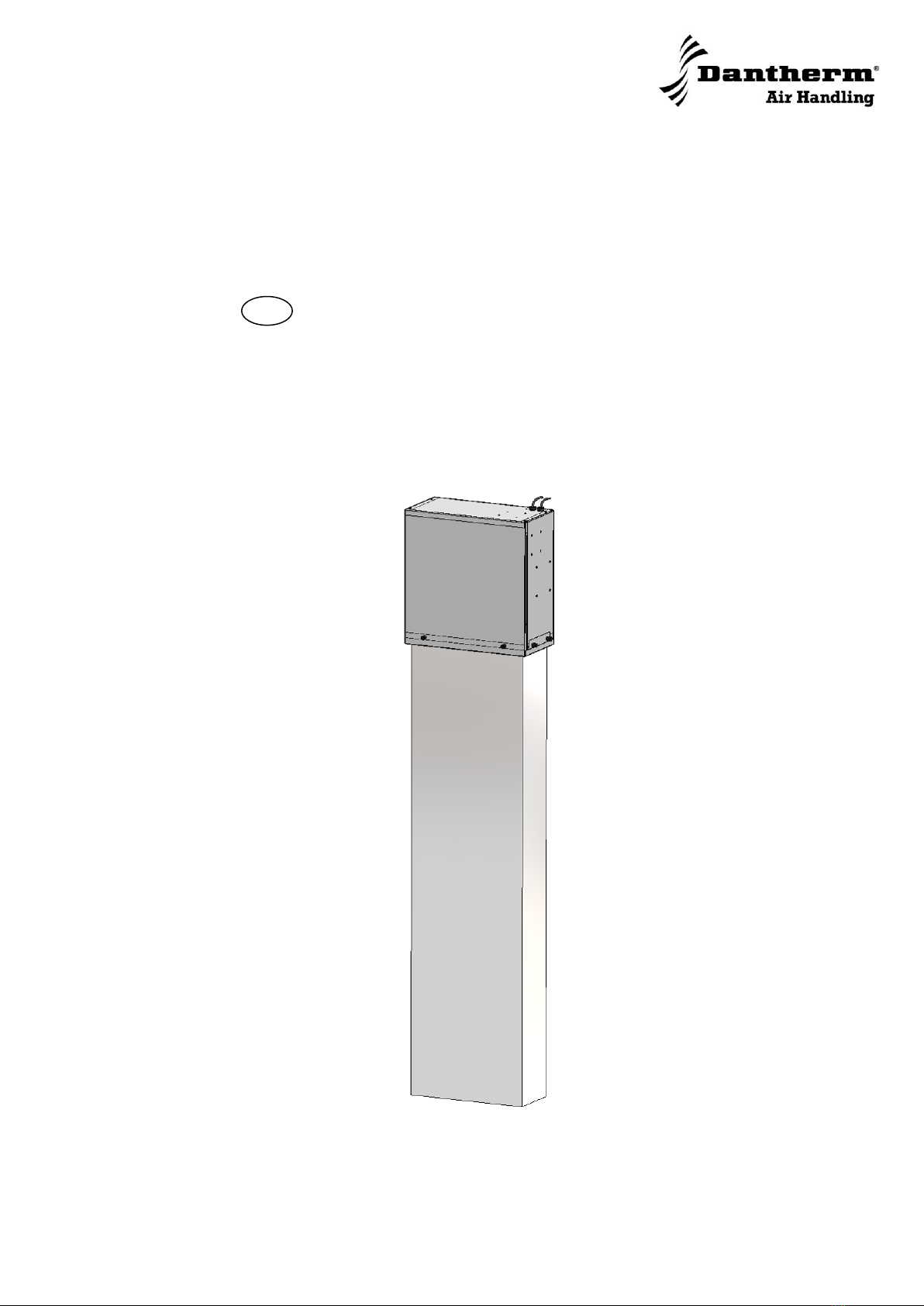
Dantherm DFC 350 User manual

Focus. Trust. Initiative.

2005 layout

DFC 350 and 450
Service manual
EN
No. 840121 • rev. 1.3 • 09.01.2012

Der tages forbehold for trykfejl og ændringer
Dantherm can accept no responsibility for possible errors and changes
Irrtümer und Änderungen vorbehalten
Dantherm n’assume aucune responsabilité pour erreurs et modifications éventuelles

3
840121 •Version 1.3 • 09.01.2012
Overview
Introduction
This is the service manual for the Displacement Free Cooling unit DFC 350 & 450.
The DCF 350-450 unit is usually shipped including a control unit. This control unit, TKS
3000A EC, ACUE 3000 or FAC 48, is covered in a separate manual.
Table of content
The Service Manual covers the following main topics:
Topic
See page
General information
4
General principle for DFC units
5
Parts and function
6
How to mount the DFC 350 and DFC 450
7
Technical data DFC 350
10
Technical data DFC 450
11
Technical data DFC 350 and 450
12
Capacity and data diagrams
13
Dimensions
15
Installation alternatives
18
Wiring diagram –ACUE 3000
19
Wiring diagram –TKS 3000A EC
20
Wiring diagram –FAC 48
21
Preventive maintenance
22
Spare parts list
23

4
General information
Introduction
This section provides general information about the unit and this Service Manual.
Target group
The target group for this Service Manual is the technicians who install, maintain and
repair the unit.
Warning
It is the responsibility of the operator to read and understand this service manual
and other information provided and to use the correct operating procedures.
The product should only be operated by qualified (trained) personnel. Failure to
do so can result in personal injury or equipment damage.
Read the entire manual before the initial start-up of the product. It is important to know
the correct operating procedures for the product and all safety precautions to prevent
the possibility of property damage and/or personal injury.
Products
The Service Manual cover the following products:
Name
Type No.
DFC 350
299763
DFC 450
299745
Copyright
Copying of this service manual, or part of it, is not allowed without written permission
from Dantherm Air Handling A/S.
Reservations
The service manual is subject to changes without notice.
CE-Declaration of
Conformity
Dantherm Air Handling A/S, Marienlystvej 65, DK7800 Skive hereby declare that the
unit are in conformity with the following directives:
2006/95/EG Low Voltage Directive including 93/68/EEC where required
86/336 EEC EMC Directive including 92/31/EEC and 93/68/EEC
98/37 EG Machine Directive
The product is manufactured with components which follow the application standards
for Low Voltage Directive and in case of norms for EMC in EU countries.
Recycling
The unit is designed to last for many years. When the time comes for the unit to be re-
cycled, the unit should be recycled according to national rules and procedures to pro-
tect the environment.

5
840121 •Version 1.3 • 09.01.2012
OUTDOOR
TEMP
SENSOR
ROOM SENSOR
DAMPER ACTIVE
COOLING UNIT
AC
SUPPLY
48V DC / 230V AC
DFC
GT1
HEATER
ST2
RADIOBASE SITE
GP
GT2
DFC FLOW
CONTROLLER
LOW DELTA-T UP TO 1,6m
General principle for DFC units
General
A DFC (Displacement Free Cooling) unit supplies the cold outdoor air through a diffu-
sor filter with very low velocity. This will make a dune of cold air at the floor and up to a
height of 1,6 meter in the shelter. The temperature at the ceiling will be relatively high.
The idea is to remove more heat with lower air volume in order to save power con-
sumption of the fan.
This is only possible if a large temperature difference between supply air and air out of
the shelter can be achieved.
Efficiency
The efficiency of the DFC unit depends very much on the circulation of the internal air
circulation in the telecom equipment and in the shelter. It is therefore very necessary to
do a thorough test of the airflows in the shelter before initiating a bigger roll out.
Illustration
The illustration below shows the DFC and some external parts unit mounted in a con-
tainer:
Parts
This table describes the different part (from left to right) in the illustration above:
Part
Description
Outdoor Temp sensor
Measures the outdoor temperature (NTC resistor)
DFC unit
The unit including bag filter and air inlet hood with com-
pact filter
GP
Supply to the unit from power source
Controller
Climate unit controller TKS3000EC, ACUE3000 or oth-
ers
Heater
External electrical heater
Supply 48V DC/230 V AC
Supply to the controller and the DFC
Room sensor GT1
Measures the indoor temperature (NTC resistor)
Active cooling unit
Existing airconditioner (often split unit)
Damper
Electrical damper allowing warm air to leave the shelter
Continued overleaf

6
Parts and function
Introduction
The DFC units have a simple but very robust design. The parts are shown below.
Illustration
This drawing shows the parts of the DFC unit. It includes a fan and a filter guard
Parts
This table describes the parts in the illustration:
Part
Description
Filter guard
Measures the pressure on both sides of the filter. When the pressure
drop exceeds 150 Pascal (factory setting) the build in switch which is
connected to the controller will open and cause an alarm.
Fan
The fan is a centrifugal fan either 48 V DC or 230 V AC. See tech-
nical data for further information.
Bag filter
The Bag filter is either filter class F5 or F6, see technical data for fur-
ther information.
Fan
Filter guard
Bag filter

7
840121 •Version 1.3 • 09.01.2012
How to Mount the DFC 350 or DFC 450
Procedure
Follow these steps to mount the DFC 350 or DFC 450:
Step
Action
1
Make a Ø245mm hole in the shelter wall about 1900 mm above the floor.
2
Demount the front cover of the unit by removing the 3 fluted grip knobs.
3
Hold the unit in position and fasten it to the wall with minimum 4 screws.
4
Slide the filter into place and remount the front cover.
DFC 350
DFC 450
f
1
2
4
2
3
3
2
1
2
3
3
4
2

8
How to Mount the DFC 350 or DFC 450, continued
Air inlet hood
Put sealing rubber on the flanges of the hood, hold it in position above the inlet hole
and fasten it to the wall.
Exhaust damper
Cut out an exhaust opening W: 1000xH: 210mm above the door (when possible).
Hold the motorized damper in position and fasten it to the wall.
Continued overleaf

9
840121 •Version 1.3 • 09.01.2012
How to Mount the DFC 350 or DFC 450, continued
Exhaust hood
Put sealing rubber on the flanges of the exhaust hood.
Hold it in position and fasten it to the wall.
Ground
Connect the DFC 450 to ground by using the nut market with ground symbol.
For more wiring information, please see section Wiring Diagram.
Electrical connec-
tion
For electrical connection of the unit see the Service Manual for the specific controller
that you are using, or see “Wiring Diagram”at the end of this manual.

10
Technical data DFC 350
Introduction
This Free Cooling unit is very compact, quiet and economic due to the Displacement
Free Cooling system. In this product the EC-fan signal is reduced to 5V to get the opti-
mized performance.
Air flow and sound
This table shows the technical data for airflow and sound pressure:
Parameter
48V DC
230V AC
Max air flow
514 m3/h
514 m3/h
Max air flow
143 l/s
143 l/s
Free cooling capacity at Δt=5°C
3 kW
3 kW
Max power consumption
40 W
35 W
Sound pressure at 5m from shelter
36 dB(A)
34 dB(A)
Sound pressure at 10m from shelter
31 dB(A)
31 dB(A)
Cabinet
This table shows the specifications for the cabinet:
Specification
Designation
DFC 350
Weight
Controller included
10 kg
Metal sheet material
Aluzinc AZ150
0,8-1,5 mm
Fan motor
This table shows the data for the fan motor:
Voltage version
48V DC
230V AC
Voltage nominal
48V DC
230V AC
Current
2,3 A
0,9 A
Max power consumption at standard settings
40 Watt
35 Watt
Speed
1500 rpm
1500 rpm
Filter
This table shows the data for the filter:
Specification
Filter data
Type
Bag filter
Filter Class
F6
Total Area
1,4 m2
Recommended filter monitor settings
150 Pa

11
840121 •Version 1.3 • 09.01.2012
Technical data DFC 350
Air flow and sound
This table shows the technical data for airflow and sound pressure:
Voltage version
48V DC
230V AC
Max air flow
1100 m3/h
1100 m3/h
Max air flow
306 l/s
306 l/s
Free cooling capacity at Δt=5°C
5 kW
5 kW
Max power consumption
40 W
61 W
Sound pressure at 5m from shelter
36 dB(A)
34 dB(A)
Sound pressure at 10m from shelter
31 dB(A)
31 dB(A)
Cabinet
Data and dimensions of the cabinet are shown in the following table:
Specification
Designation
DFC 450
Weight
Controller excluded
13 kg
Metal sheet material
Aluzinc AZ150
0,8-1,5 mm
Fan motor
Data of the fan motor is shown in the following table:
Voltage version
48V DC
230V AC
Voltage nominal
48V DC
230V AC
Current
2,3 A
1,1 A
Max power consumption
40 W
54 W
Speed
1200 rpm
1200 rpm
Filter
In the table below the data of the filter are specified:
Specification
Filter data
Filter data
Type
Bag filter
Filter Class
F5
F6
Total Area
2 m2
Recommende filter monitor setting
100 Pa
150 Pa
Electrical heater,
This table shows the voltage and power consumption of the electrical heater (optional):
Specification
Value
Power, Voltage
1300 W, 230 V AC

12
Technical data DFC 350 and 450
Controls
The table below show the specification for the 2 controllers for the DFC unit:
Specification
48V DC
230V DC
Enclosure IP65
DIN rail mounting
Enclosure IP65
Standard control units
(See separate manu-
als)
ACUE 3000
TKS 3000 EC
Special control units
(See separate manu-
als)
FAC 48
Indoor temperature
sensor
RG-TD5
RG-TD5
RG-TD5
Outdoor temperature
sensor
UG-TD5 (optional)
UG-TD5 (optional)
UG-TD5 (optio-
nal)
Filter monitor
JDW5 (optional)
JDW5 (optional)
JDW5 (optional)

13
840121 •Version 1.3 • 09.01.2012
Capacity and data diagrams
Performance
The diagram below shows data for DFC 350:
Airflow & Pressure
drop
The diagram below shows data for DFC 350:
Performance
The diagram below shows data for DFC 450:
Continued overleaf
DFC 350 Performance & Power Consumption
5
11
20,0
30
48
75
114
0
100
200
300
400
500
600
700
800
900
1000
20% 30% 40% 50% 60% 70% 100%
% fan speed
Airflow [m3/h]
0
500
1000
1500
2000
2500
3000
3500
4000
4500
5000
Cooling performance [W]
Power conption DFC 450 [W]
Air flow m3/h
Cooling capacity (kW @ ∆t=5°C)
Cooling performance is
calculated from outdoor
temperature and indside
temperature in 1,6m height
Fan working range 15% to 50%
DFC 350 Airflow & Pressure drop
0
20
40
60
80
100
120
140
160
180
20% 30% 40% 50% 60% 70% 100%
Fan %speed
Pressure drop [Pa]
0
100
200
300
400
500
600
700
800
900
1000
Airflow [m3/h]
Pressure drop Filter (Pa)
Air flow m3/h
DFC 450 Performance & Power Consumption
8
15
25,0
37
61,7
104
0
200
400
600
800
1000
1200
1400
1600
20% 30% 40% 50% 70% 100%
%fan speed
Airflow [m3/h]
0
1000
2000
3000
4000
5000
6000
Cooling performance [W]
Power conption DFC 450 [W]
Air flow m3/h
Cooling capacity (kW @ ∆t=5°C)
Cooling performance is
calculated from outdoor
temperature and indside
temperature in 1,6m height
Fan working range 15% to 50%

14
Capacity and data diagrams, continued
Airflow & Pressure
drop
The diagram below shows data for DFC 450:
DFC 450 Airflow & Pressure drop
0
20
40
60
80
100
120
20% 30% 40% 50% 70% 100%
Fan %speed
Pressure drop [Pa]
0
200
400
600
800
1000
1200
1400
1600
Airflow [m3/h]
Pressure drop Filter (Pa)
Air flow m3/h

15
840121 •Version 1.3 • 09.01.2012
Dimensions
Illustration DFC 350
The drawings below illustrate the dimensions of the DFC 350.
Continued overleaf
HOLE CUT OUT
DIMENSION:
Ø245

16
Dimensions, continued
Illustration DFC 450
The drawings below illustrate the dimensions of the DFC 450.
Continued overleaf
HOLE CUT OUT
DIMENSION:
Ø305

17
840121 •Version 1.3 • 09.01.2012
Dimensions, continued
External ac-
cessories
Air inlet hood with net:
940-60299654
Exhaust air rain hood
FC1100x220:
940-30205576
Motorized Exhaust air
damper SP1000x211
48VDC: 940-02130724
230V DC: 940-02130230
HOLE CUT OUT DIMEN-
SIONS (WxH):
1000x210mm

18
Installation alternatives
Introduction
The pictures below shows the three ways the Displacement Free Cooling unit can be
mounted and still make filter exchange easy. There are three different lids, of which on-
ly one should be opened to take out and replace the bag filter.
Front service
Left and
right ser-
vice
This manual suits for next models
1
Table of contents
Other Dantherm Air Conditioner manuals

Dantherm
Dantherm iA/C T Series Quick setup guide

Dantherm
Dantherm 3000 User manual

Dantherm
Dantherm CDT 90 MKII User manual

Dantherm
Dantherm AC-24 User manual

Dantherm
Dantherm iA/C T-A6000, iA/C T-B6000, iA/C T-B8000 Dimensional drawing

Dantherm
Dantherm Hex 6 A User manual

Dantherm
Dantherm Master BCF 330AB Manual

Dantherm
Dantherm 3500 User manual

Dantherm
Dantherm ACT-7 Series User manual

Dantherm
Dantherm Combo Cooling 10000/1000 User manual