Dantherm Combo Cooling 10000/1000 User manual

Combo Cooling 10000/1000
Quick setup guide
Rev. 0.56

2
This installation manual and the product use various displays and labels to ensure safe use. Ig-
noring these displays and labels and incorrectly using the product could have results as classied
below. Please read the following warning symbol information before reading the rest of this sec-
tion, and be sure to strictly observe all instructions.
Not following these instructions could result in death or serious injury
Not following these instructions could result in injury or property da-
mage.
The symbol means something that should NOT be done
Project safety is your responsibility!
Follow the instructions in this manual regarding the installation method and installation orienta-
tion. Not following these instructions could result in injury, death, or damage to equipment.
All work should be performed by qualied personal using safe work practices.
All proper personal protective equipment should be used. PPE required for this installation inclu-
des but is not limited to:
• Safety glasses
• Hard hat
• Safety shoes
• Hearing protection
• Cut resistant gloves
• Face shield
• Proper work attire (long sleeve shirt and long pants)
Please strictly observe the following: Special Skill is required to install the Dantherm Combo
Cooling units. Non-qualied personnel should not attempt any of the actions shown in this instal-
lation guide. Dantherm shall not be responsible for improper installation or any accidents, dama-
ge, or injury resulting from improper installation.
Warning
Caution
Warning
Caution
Warnings

3
1x
1x ~
1x DIN 10 mm
1x
8-28x
1x
1x or
1x
2x
8 mm
4 mm
3 mm
Tools needed
8 mm
4 mm
3 mm

4
12.72 in
10.51 in
31.50in
3.94 in
31.50 in
3.94 in
61.97 in
36.30 in 26.06 in
19.69 in
1.93 in
41.57 in
42.20 in
81.18 in
23.54 in
7.12 in
81.18 in
Top view - service space
15.75 in 15.75 in
56.69 in
507 lbs !
Product dimension
Imperial
Top view - exempted space

5
Product dimension
Metric
1056 mm
1072 mm
922 mm
500 mm
323 mm
800 mm
267 mm
800 mm
49 mm
662 mm
100 mm
100 mm
598 mm
181 mm
Top view - service space
400 mm
400 mm
1440 mm
230 kg !
Top view - exempted space

6
Product overview
Left side panel
Mounting frame
Evaporator fan
Cooling air lter
CC4 control board
Evaporator
Internal damper motor
Damper
Condenser
Condenser fan
Compressor
Integrated rain hood
Cable entrance
Condensate water drainage
Lower air grill- condenser air inlet
Serial number label

7
Free cooling air inlet
Shown “Air Maze” is optional
Right side panel
Integrated rain hood

8
Remove covers
Release lower
air grill
1
2
3
1 1
2
2
4

9
Release mou-
ting frame
Locate possible
cable routing
AC+HEAT
DC
Display and temp sensor
8 mm
4 mm
3 mm
2x DIN 10
8 mm
4 mm
3 mm
2x DIN 10
Controller board
Terminal block
Warning
Caution

10
Cut out
Mounting of
frame
8 mm
4 mm
3 mm
min. 925 mm
optimum 1125 mm
or more
500 mm
323 mm
275 mm
min. 90 mm
800 mm
800 mm
364 mm
25 mm
30 mm
30 mm
Drill only cable
inlet if needed
8 mm
4 mm
3 mm
min 8x
Use appropiate screw amount
and type according to wall
structure
Warning
Caution
Warning
Caution

11
Lifting unit
onto bracket
or
Securing and
sealing
8 mm
4 mm
3 mm
8 mm
4 mm
3 mm
Hoist unit with forklift or equal placed
under bottom main cabinet
4x DIN 10
Warning
Caution

12
Mounting dis-
play
2x
8 mm
4 mm
3 mm
8 mm
4 mm
3 mm

13
Mounting in-
door sensor
Keep this space free
for air ow

14
Unit schematics - 400V/50Hz - 3 phase
Filiter guard + : 2 pin
Filiter guard - : 3 pin
Screw GND
Yellow: PWM
Ext. Fan
V
U W
Compressor U
V
w
Int. Fan
White: Tach output
Blue: GND
Red: 48V
J2/Fan 1
J3/Fan 2
J7/Fan 3
J15
J10
J11
Postive
Tacho
PWM
Gnd
Heater output -
Condensor fan output +
Condensor fan output -
Heater output +
Damper GND
Compressor out +
Compressor out -
Damper supply
Damper supply
Supply temp. Sensor +
Supply temp. Sensor -
Ambient temp.Sensor -
Ambient temp.Sensor +
Condensor fan Sensor +
Condensor fan Sensor -
Door Switch input -
Door Switch input +
Phase monitor input +
Phase monitor input -
Filiter guard -
Filiter guard +
Screw GND
GND
N
output +
input -
L1
L2
Door SW
output -
Ext. fan
Contactor
3 Phase Power Input
400V 50Hz C20A Fuse
GND
N
L3
L2
L1
Terminal Block
w
V
U
L3
L2
L1
L1
L2
L3
14
11
12
L1N
PWMGND
Black:L Blue:N
Blue:GND
Yellow:PWM
2:Supply
3:Supply
1:GND
A2
A1
PWM
NL1
GND
Gnd
PWM
Tacho
Postive
Gnd
L3
Cond. fan
-
Monitor
Phase
PWM
Tacho
Postive
Comp.
-
Compressor out +
Compressor out -
Filter
Ambient temp.Sensor
Supply temp. Sensor
Compressor
Condensor fan Sensor
HP
control
control
LP
Heater
+
Heater
-
+
Heater Heater +
Heater -
Damper
Con d. fa n
output +
-
Heater
Condensor fan Sensor -
Door Switch input +
output -
Con d. fa n
Door Switch input -
Door SW
input +
Door SW
input -
Door SW
input +
Comp.
Con d. fa n
Condensor fan Sensor +
External safety breaker
Not included
Heat output - relay driver
48V DC – 300mA max
+ -
Relay not included.
Use fx ABB AF12Z-30-01-21
230V HEAT OUT
N
L1 GND
CC4 controller
PCB board
N
L1
L2
L3
GND
Orange=OK
Warning
Caution

15
Filiter guard + : 2 pin
Filiter guard - : 3 pin
Screw GND
Yellow: PWM
Ext. Fan
V
U W
Compressor U
V
w
Int. Fan
White: Tach output
Blue: GND
Red: 48V
J2/Fan 1
J3/Fan 2
J7/Fan 3
J15
J10
J11
Postive
Tacho
PWM
Gnd
Heater output -
Condensor fan output +
Condensor fan output -
Heater output +
Damper GND
Compressor out +
Compressor out -
Damper supply
Damper supply
Supply temp. Sensor +
Supply temp. Sensor -
Ambient temp.Sensor -
Ambient temp.Sensor +
Condensor fan Sensor +
Condensor fan Sensor -
Door Switch input -
Door Switch input +
Phase monitor input +
Phase monitor input -
Filiter guard -
Filiter guard +
Screw GND
GND
N
output +
input -
L1
L2
Door SW
output -
Ext. fan
Contactor
3 Phase Power Input
400V 50Hz C20A Fuse
GND
N
L3
L2
L1
Terminal Block
w
V
U
L3
L2
L1
L1
L2
L3
14
11
12
L1N
PWMGND
Black:L Blue:N
Blue:GND
Yellow:PWM
2:Supply
3:Supply
1:GND
A2
A1
PWM
NL1
GND
Gnd
PWM
Tacho
Postive
Gnd
L3
Cond. fan
-
Monitor
Phase
PWM
Tacho
Postive
Comp.
-
Compressor out +
Compressor out -
Filter
Ambient temp.Sensor
Supply temp. Sensor
Compressor
Condensor fan Sensor
HP
control
control
LP
Heater
+
Heater
-
+
Heater Heater +
Heater -
Damper
Con d. fa n
output +
-
Heater
Condensor fan Sensor -
Door Switch input +
output -
Con d. fa n
Door Switch input -
Door SW
input +
Door SW
input -
Door SW
input +
Comp.
Con d. fa n
Condensor fan Sensor +
External safety breaker
Not included
Heat output - relay driver
48V DC – 300mA max
+ -
Relay not included.
Use fx ABB AF12Z-30-01-21
230V HEAT OUT
N
L1 GND
CC4 controller
PCB board
N
L1
L2
L3
GND
Orange=OK

16
Unit schematics - 240V/60Hz - 1 phase
Condensor fan Sensor
output +
LP
Filiter guard - : 3 pin
input +
Condensor fan output +
Screw GND Ext. Fan
V
U W
Compressor C
R
S
Int. Fan
Filiter guard + : 2 pin
Blue: GND
Red: 48V
J2/Fan 1
J3/Fan 2
J7/Fan 3
J15
J10
J11
Postive
Tacho
PWM
Gnd
Heater output -
Condensor fan Sensor -
Condensor fan output -
Heater output +
Damper GND
Compressor out +
Compressor out -
Damper supply
Damper supply
Supply temp. Sensor +
Supply temp. Sensor -
Ambient temp.Sensor -
Ambient temp.Sensor +
Condensor fan Sensor +
Condensor fan Sensor -
Door Switch input -
Door Switch input +
Phase monitor input +
Phase monitor input -
Filiter guard -
Filiter guard +
65
White: Tach output
Con d. fa n
Screw GND
GND
L2
L1
Ext. fan
Contactor
1 Phase Power Input
240V 60Hz C40A fused
GND
L2
L1
Terminal Block
N
L
NL
LN
PWMGND
Black:L Blue:N
Blue:GND
Yellow:PWM
2:Supply
3:Supply
1:GND
A2
A1
PWM
NL
GND
Gnd
PWM
input +
Door SW
-
Door SW
Tacho
Postive
Gnd
PWM
Tacho
Postive
Comp.
-
Compressor out +
Compressor out -
input -
Door SW
Filter
Ambient temp.Sensor
output -
Supply temp. Sensor
Cond. fan
HP
Condensor fan Sensor +
Heater
+
Compressor
control
Heater
-
Heater +
Heater -
control
+
Damper
Con d. f an
Heater
-
output +
Yellow: PWM
Heater
output -
Door Switch input +
Door SW
input -
Comp.
Con d. f an
Capactior
Heat output - relay driver
48V DC – 300mA max
+ -
External safety breaker
Not included
Relay not included.
Use fx ABB AF12Z-30-01-21
240V HEAT OUT
GND
L2
L1
CC4 controller
PCB board
L2
L1
GND
Warning
Caution

17
Condensor fan Sensor
output +
LP
Filiter guard - : 3 pin
input +
Condensor fan output +
Screw GND Ext. Fan
V
U W
Compressor C
R
S
Int. Fan
Filiter guard + : 2 pin
Blue: GND
Red: 48V
J2/Fan 1
J3/Fan 2
J7/Fan 3
J15
J10
J11
Postive
Tacho
PWM
Gnd
Heater output -
Condensor fan Sensor -
Condensor fan output -
Heater output +
Damper GND
Compressor out +
Compressor out -
Damper supply
Damper supply
Supply temp. Sensor +
Supply temp. Sensor -
Ambient temp.Sensor -
Ambient temp.Sensor +
Condensor fan Sensor +
Condensor fan Sensor -
Door Switch input -
Door Switch input +
Phase monitor input +
Phase monitor input -
Filiter guard -
Filiter guard +
65
White: Tach output
Con d. fa n
Screw GND
GND
L2
L1
Ext. fan
Contactor
1 Phase Power Input
240V 60Hz C40A fused
GND
L2
L1
Terminal Block
N
L
NL
LN
PWMGND
Black:L Blue:N
Blue:GND
Yellow:PWM
2:Supply
3:Supply
1:GND
A2
A1
PWM
NL
GND
Gnd
PWM
input +
Door SW
-
Door SW
Tacho
Postive
Gnd
PWM
Tacho
Postive
Comp.
-
Compressor out +
Compressor out -
input -
Door SW
Filter
Ambient temp.Sensor
output -
Supply temp. Sensor
Cond. fan
HP
Condensor fan Sensor +
Heater
+
Compressor
control
Heater
-
Heater +
Heater -
control
+
Damper
Con d. f an
Heater
-
output +
Yellow: PWM
Heater
output -
Door Switch input +
Door SW
input -
Comp.
Con d. f an
Capactior
Heat output - relay driver
48V DC – 300mA max
+ -
External safety breaker
Not included
Relay not included.
Use fx ABB AF12Z-30-01-21
240V HEAT OUT
GND
L2
L1
CC4 controller
PCB board
L2
L1
GND

18
J1
J5
J9
J4
J16
J17
J6
J11
J10
J15
J7
J3
J2
AL 1
AL 2
AC 1
AC 2
Potential free
Max. 42VAc or 60VDc. / 3A - (SELV)
Default normally open - jumper changeable
RS485 in
RS485 out
TTL
1=Gnd
2=B
3=Gnd
4=A
5-8=nc
1=Gnd
2=B
3=Gnd
4=A
5-6=line pwr gnd
7-8=12v line pwr
PC interface - galvanic isolated
Gnd
Room sensor
Gnd
Digital input 1
Gnd
Digital input 2
Alarm 2
Alarm 2
Alarm 1
Alarm 1
AC 2
AC 2
AC 1
AC 1
Ext. damper GND
Ext. damper close
Ext. damper open
SD reader
48V DC negative
48V DC positive
48VDC
20A fused
External safety breaker
(not included)
-t°
0 / 12V DC
with pull up
48V DC/100mA
Pre wired
See unit schematics
Comp. out 1
Comp GND
Damper open
Damper close
Damper GND
Heater out +
Heater out GND
Condenser fan out +
Condenser out GND
Amb temp sens
Amb temp sens GND
Supply temp sens
Supply temp sens GND
Condenser temp sens
Condenser temp sens GND
Phase monitor input
Phase monitor input GND
Filter guard input
Filter guard input GND
Door switch input
Door switch GND
1: Fan positive
2:Fan PWM
3:Fan tacho
4:Fan GND
1: Fan positive
2:Fan PWM
3:Fan tacho
4:Fan GND
1: Fan positive
2:Fan PWM
3:Fan tacho
4:Fan GND
Standard shielded ethernet cable
(568A termination both ends)
10A Mini blade terminal.
FX ”Littlefuse” type ”997 010”
10A Mini blade terminal.
FX ”Littlefuse” type ”997 010”
10A Mini blade terminal.
FX ”Littlefuse” type ”997 010”
SD card slot for setup and logging
Green LED
Red LED
F2
F3
F4
Controller connections

19
J1
J5
J9
J4
J16
J17
J6
J11
J10
J15
J7
J3
J2
AL 1
AL 2
AC 1
AC 2
Potential free
Max. 42VAc or 60VDc. / 3A - (SELV)
Default normally open - jumper changeable
RS485 in
RS485 out
TTL
1=Gnd
2=B
3=Gnd
4=A
5-8=nc
1=Gnd
2=B
3=Gnd
4=A
5-6=line pwr gnd
7-8=12v line pwr
PC interface - galvanic isolated
Gnd
Room sensor
Gnd
Digital input 1
Gnd
Digital input 2
Alarm 2
Alarm 2
Alarm 1
Alarm 1
AC 2
AC 2
AC 1
AC 1
Ext. damper GND
Ext. damper close
Ext. damper open
SD reader
48V DC negative
48V DC positive
48VDC
20A fused
External safety breaker
(not included)
-t°
0 / 12V DC
with pull up
48V DC/100mA
Pre wired
See unit schematics
Comp. out 1
Comp GND
Damper open
Damper close
Damper GND
Heater out +
Heater out GND
Condenser fan out +
Condenser out GND
Amb temp sens
Amb temp sens GND
Supply temp sens
Supply temp sens GND
Condenser temp sens
Condenser temp sens GND
Phase monitor input
Phase monitor input GND
Filter guard input
Filter guard input GND
Door switch input
Door switch GND
1: Fan positive
2:Fan PWM
3:Fan tacho
4:Fan GND
1: Fan positive
2:Fan PWM
3:Fan tacho
4:Fan GND
1: Fan positive
2:Fan PWM
3:Fan tacho
4:Fan GND
Standard shielded ethernet cable
(568A termination both ends)
10A Mini blade terminal.
FX ”Littlefuse” type ”997 010”
10A Mini blade terminal.
FX ”Littlefuse” type ”997 010”
10A Mini blade terminal.
FX ”Littlefuse” type ”997 010”
SD card slot for setup and logging
Green LED
Red LED
F2
F3
F4
Warning
Caution

20
Control strategy
HEATER ON
Free Cooling mode
High Speed
Free Cooling mode
Emergency
Mode
Shelter Temperature
[°C]
INTERNAL COMPRESSOR
EXTERNAL A/C UNIT 1
ALL AVAILABLE A/C’s ON
AC mode
Dampers Open
Dampers Closed
Dampers Close
Dampers
Open
Circulation mode
Heater mode
PBand
TSetpoint
TSetpoint Heater
TAC Start
Idle Band
TAC Start 1
Diff temp Diff temp 1
EXTERNAL A/C UNIT 2
Diff temp 2
TAC Start 2
PBand heater
Table of contents
Other Dantherm Air Conditioner manuals
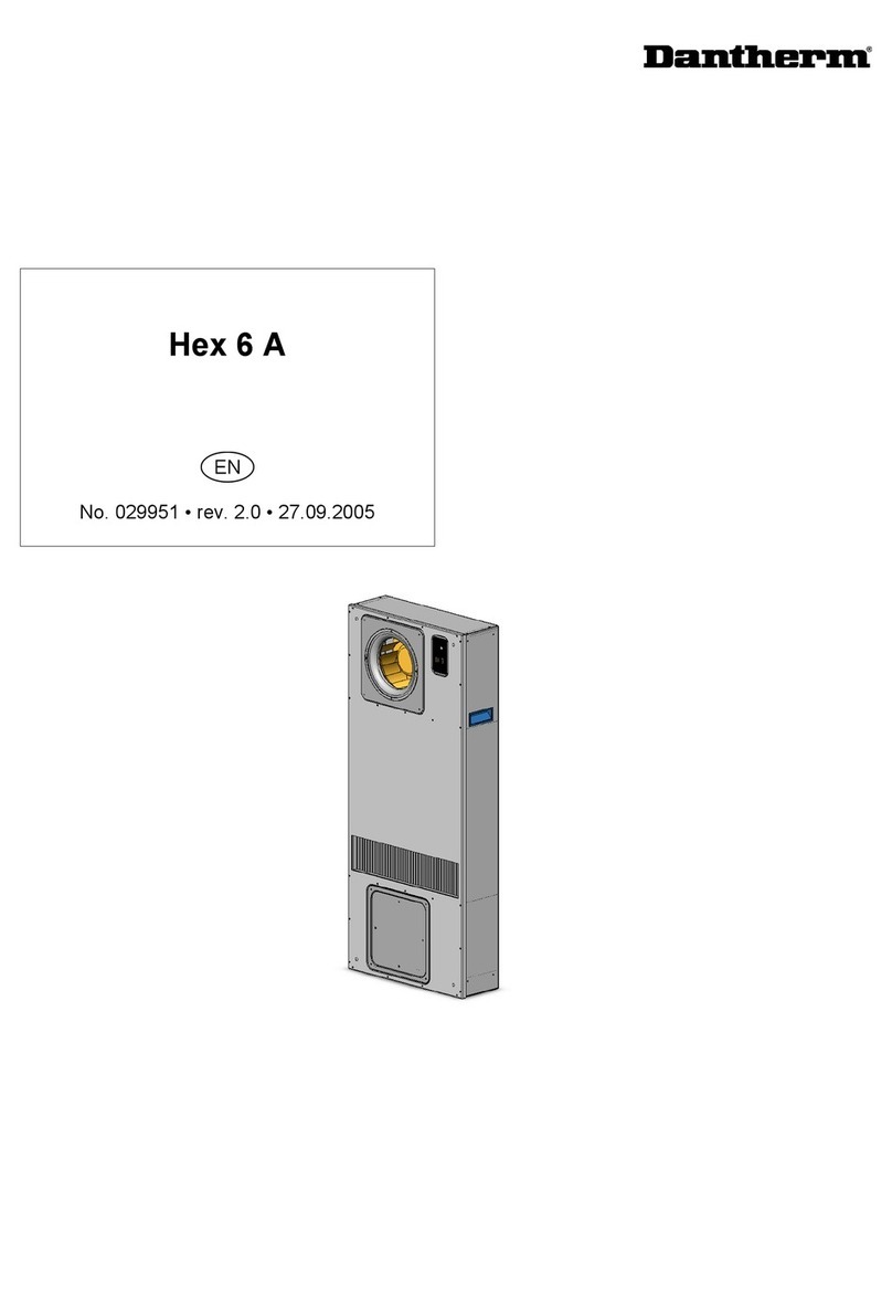
Dantherm
Dantherm Classic 20 CS020020A Dimensional drawing

Dantherm
Dantherm 3000 User manual

Dantherm
Dantherm CS030040A Dimensional drawing

Dantherm
Dantherm 4000 Series User manual

Dantherm
Dantherm iA/C T-A6000, iA/C T-B6000, iA/C T-B8000 Dimensional drawing

Dantherm
Dantherm CDT 90 MKII User manual

Dantherm
Dantherm ACT-7 Series User manual

Dantherm
Dantherm AC-24 User manual

Dantherm
Dantherm DFC 350 User manual
Dantherm
Dantherm Flexibox 900 User manual