Danzo DH0196 Guide

OPERATION AND PARTS MANUAL
DH0196 20G Connect and Cut H
y
draulic Chain Saw
Information subject to change without notice.

SAFETY PRECAUTIONS
⇒The unit you have purchased may require you to install additional guarding to meet State and
Federal safety requirements.
⇒Do not move the log when it is being cut or when the saw is down. This action may damage the
bar, chain or other components or could cause bodily harm or injury.
⇒The log must be clamped before cutting. The bar, chain or other components could be
damaged. You could suffer bodily harm or injury.
⇒Do not make repairs or adjustments to this product other than those listed in this manual
except when directed to do so by Danzco, Inc.
⇒All persons working near this machine must wear eye protection and hearing protection.
⇒Use extreme caution around the cutting chain. It is sharp and may cause bodily harm or
injury.
⇒Petroleum products are used with this product. Use appropriate caution when operating or
servicing. These products are flammable and may cause eye or skin irritation.
⇒Always use Danzco, Inc. approved parts when making repairs. Replacement parts must meet
or exceed the specifications of the original equipment manufacturer.
⇒The information in this manual is subject to change without notification.
⇒This manual is intended for safe operation and maintenance of the Danzco, Inc., 20G Connect
and Cut Hydraulic Chain Saw. Danzco, Inc., welcomes any and all suggestions on how to
improve this manual or the 20G Connect and Cut Hydraulic Chain Saw.
2

Table of Contents
Cover page................................................................................................................................................................1
Safety Precaution ...................................................................................................................................................2
Table of Contents...................................................................................................................................................3
Introduction............................................................................................................................................................4
Warranty ................................................................................................................................................................4
Installation..............................................................................................................................................................4
Hydraulic Connections...........................................................................................................................................5
Chain Tension and Sharpening..............................................................................................................................6
Sprocket Removal and Replacement .....................................................................................................................6
Feed Control Adjustment....................................................................................................................................... 7
Bar Oil Pump Adjustment......................................................................................................................................8
Operating Instruction .............................................................................................................................................9
Parts and Service Information................................................................................................................................9
Main Sub Assembly Parts.................................................................................................................................... 10
Bar Plate Assembly Parts..................................................................................................................................... 11
Feed Cylinder Assembly Parts.............................................................................................................................12
Bar Oil Pump Assembly Parts .............................................................................................................................13
Feed and Motor Control Manifold Parts.............................................................................................................. 14
Bar Oil Tank Assembly Parts............................................................................................................................... 15
Hose Layout.........................................................................................................................................................16
3

0BIntroduction
Thank you for purchasing a Danzco, Inc. product. Our goal is to provide quality products for your job. This
manual contains warranty information, installation information, operation instructions, parts ordering information,
service contact information.
1BWarranty
This Danzco, Inc. product carries a one year or 2000 hour warranty on the Danzco, Inc. designed and built
components covering material and workmanship. Purchased components carry the manufactures warranty. This
warranty does not cover normal wear from use, damage from abuse or misuse, damage from contamination,
damage from natural disasters, fire damage or incorrect installation. This warranty does not cover labor to remove
and replace parts, shipping and handling of parts or shipping and handling for items returned for repair. If any
component fails you must contact Danzco, Inc. at (360)264-2141 before doing any repair work. We will provide
assistance to obtain warranty from other manufactures on their components.
2BInstallation
When you receive the two boxes containing parts, you will need to reassemble the unit. The larger box (Fig. 2)
contains the main frame sub assembly, (Fig.1, items 1 and 2). The smaller long box (Fig. 3) contains the feed
cylinder (Fig. 1, item 3), feed and motor control valve (Fig. 1, item 4), bar oil tank (Fig. 1, item 5), bar guard
(Fig. 1, item 6), bar oil pump (Fig. 1, item 7), saw bar (Fig. 1, item 8), saw chain (Fig. 1, item 9), weld down
mount plate (Fig. 1, item 10), and assembly fasteners.
Fig. 1 Fig. 2 Fig. 3
4

After assembling the components as shown in figure 1, position the saw bar square to the log, at the correct height
with clearance between the bar guard and the side of the largest log and weld down solidly (Fig. 4).
Fig. 4
3BHydraulic Connections
The hydraulic requirements to operate the saw are 19 to 21 gallons per minute at 2000 psi from a directional
control valve that has port A and B blocked in the neutral position. These pictures are examples of valve spool
that will work. The hydraulic valve can be manual or electric control. Figure 5
shows hose connections for correct operation.
Fig. 5
5

The return hose can be #8 or 1/2” diameter for the first three feet, if a longer hose is required it must be #12 or
3/4” up to thirty feet. If the total return hose length is greater than thirty three feet #16 or 1” hose should be used.
The filter must be rated for 20 GPM plus any additional pump flowing into it. Failure to properly size the hose
and filter or properly connect the return hose to a filter and tank will shorten the motor shaft seal life and will not
be covered by warranty.
4BChain Tension and Sharpening
Figure 6 shows the chain tensioning screw. A #2 or #3 Phillips screwdriver is required to turn the tension screw.
With the supplied sprocket nose saw bar supplied proper tension is when the cutters come off the rails roughly
1/8” with a tug of finger pressure. Refer to the Oregon Mechanical Timber Harvesting Handbook for more
tensioning information and sharpening information.
Fig. 6
Fig. 7
5BSprocket Removal and Replacement
The chain saw sprocket is connected to the shaft with a tapered bushing. To remove the sprocket remove the Cap
Screws (Fig 7, item 3) and screw them into the Threaded Holes, tighten up to 36 inch pounds to push the Sprocket
(Fig 7, item 1) off the bushing. You may need to tap the Sprocket towards the motor with a hammer to assist in
getting the Sprocket loose from the Bushing (Fig 7, item 2). Lightly drive a flat blade screwdriver into the slot of
the Bushing.
6

Pry between the Bushing and the Sprocket to get the Bushing off the shaft. Watch that the Drive Key (#4, Fig 7)
does not get lost.
To install the Sprocket, slide the Sprocket (Fig 7, item 1) over the motor shaft, slide the Bushing (Fig 7, item 2)
onto the shaft with the Drive Key (Fig 7, item 4) aligned. Position the sprocket groove offset towards the motor
about the width of the bar groove with the Bushing just contacting the Sprocket. Insert the Cap Screws (Fig 7,
item 3) through the large hole in the Bushing and screw them into the threaded holes of the Sprocket. Torque the
Cap Screws (Fig 7, item 4) to 36 inch pounds. Check to make sure the sprocket groove is aligned with the bar
groove. If the alignment is not correct, remove and replace the sprocket and bushing by adjusting the position
before tightening the cap screws.
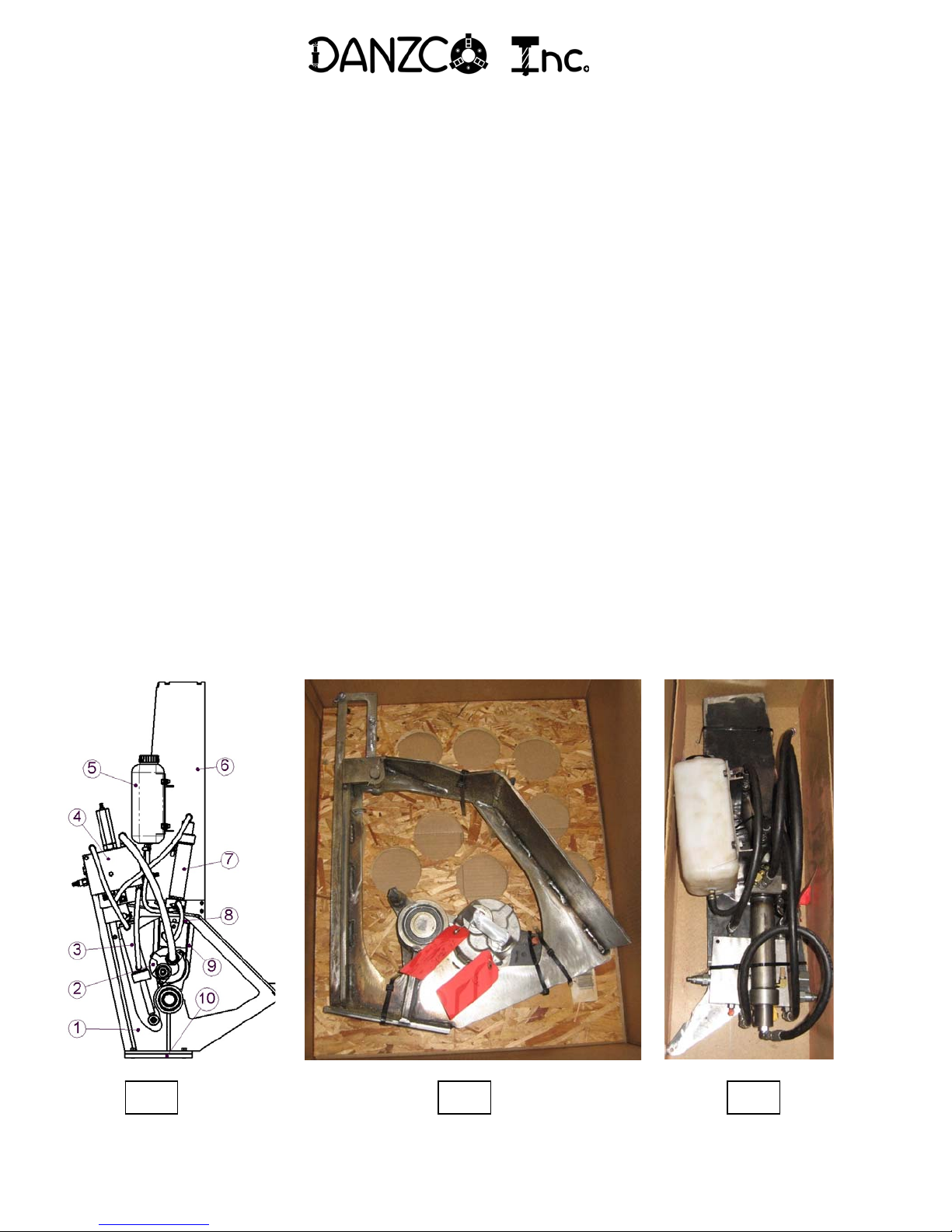
6BFeed Control Adjustments
Connect and Cut saw systems have a control manifold with cartridge valves to limit flow to the saw motor and
feed cylinder and a feed modulating valve to adjust the feed speed based on the saw motor pressure. We have
tested the operation of your system to set the valves before shipping so your system should cut any diameter,
species, or hardness of wood without stalling the chain in the cut. The feed modulating valve will make the bar
pulsate in the cut on larger or harder wood as it is trying to cut as fast as possible. It may be possible to fine tune
the cutting for your application by adjusting the saw feed speed adjustment valve (Fig.8, item 10). For larger or
harder wood loosen the jam nut with a 9/16” wrench and screw the adjustment screw out with a 5/32” hex key
wrench (Allen wrench), this will slow the bar movement down, lock the jam nut down when done adjusting. For
smaller softer wood you may want to speed up the bar movement by screwing the adjustment screw in. Having
the bar move too fast may cause the chain to stick when starting into the cut if the chain hits a knot. It is possible
to tune the feed modulating valve (Fig. 8, item 2) by loosening the jam nut with a 9/16” wrench and adjusting the
screw with a 3/16 hex key. A smoother cut may be possible by screwing the adjustment screw out but this may
increase the cutting time in larger or harder wood. If the wood is dry and hard, screwing the feed modulating
adjustment in may decrease cutting time. Screwing the feed modulating adjustment in too far will cause the chain
to stall. Be sure to lock the jam nut after adjusting a valve.
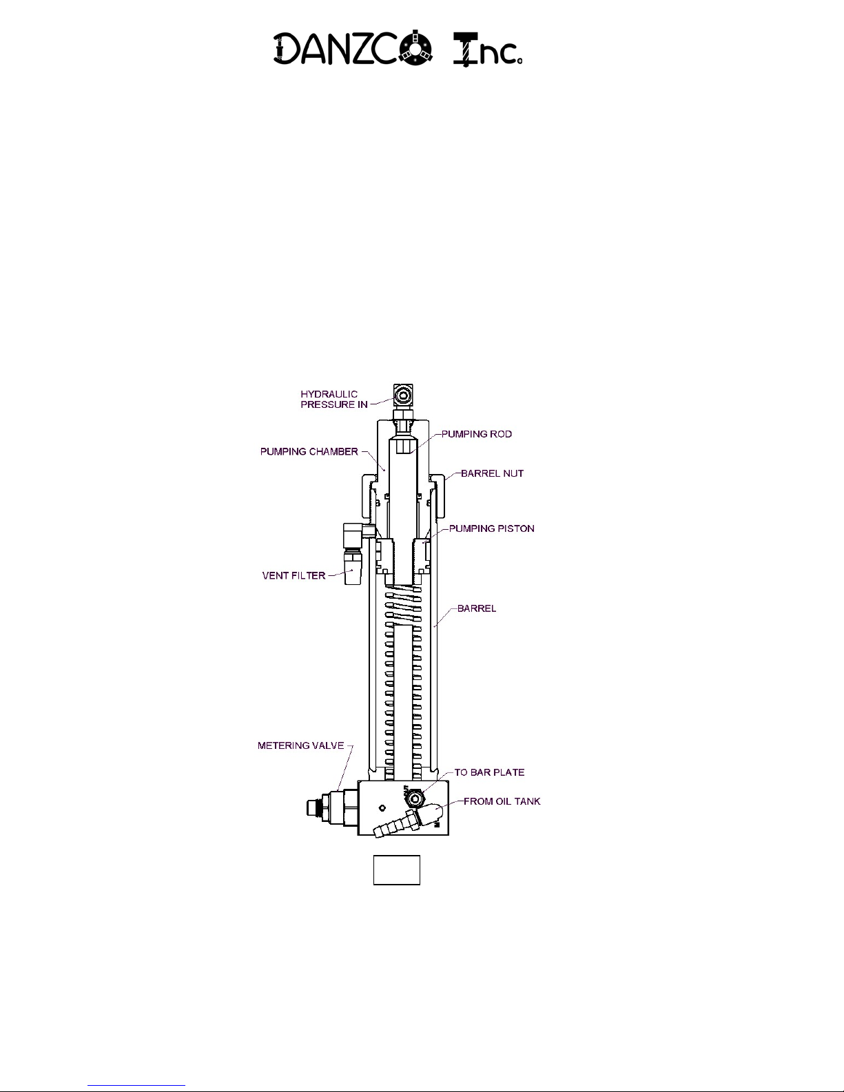
Fig. 8
7

7BBar Oil Pump Adjustments
The DH0144 bar oil pump (Fig. 9) is a single acting pump that can pump up to 32 cc or 1.08 oz. of bar oil per
cycle, enough for about 30 seconds of cutting. There is a hose connected to the feed and motor control valve
manifold (Fig. 8, item 6) that connects to the fitting (Fig.9, hydraulic pressure in) on the bar oil pump. When a cut
is started flow and pressure from the manifold pushes on the pumping rod and piston to force a metered amount of
oil to the bar. The metering valve in Figure 8 is sensitive to volume adjustment. Turning it clockwise reduces the
speed oil is pumped and turning it counterclockwise increases the speed the oil comes out. If you run the tank out
of oil you may need to prime the pump. To prime the pump remove the barrel nut and pull the pumping chamber,
pumping piston and pumping rod. Fill the barrel with bar oil up to the vent hole. Reinstall the pumping rod
assembly into the pumping chamber with care to not damage the rod seal. Reinstall the pumping chamber and
pumping rod assembly into the barrel with care to not damage the piston or the o-ring and retighten the barrel nut.
To reduce the chance of seal damage make sure the seals are oiled and wiggle in a circular motion as you push the
parts together.
Fig. 9
8

8BOperating Instructions
Before and periodically during operation you must check the bar oil level and chain tension. We recommend
using a good quality bar oil of the correct viscosity for your areas operating temperatures. Because of the wide
temperature range between winter and summer two different viscosity oils may be required. Tension the chain as
described on page 6. The log being cut must be clamped prior to sawing. Once the log is positioned and clamped
the saw control valve needs to be opened for full flow to cut. After completing the cut reverse the valve and raise
the saw bar. The saw motor only runs when the bar is being lowered. The bar will only receive up to 32 cc of oil
when the saw motor is operating or the bar is feeding down.
9BParts and Service Information
For parts and service contact Danzco, Inc. Our hours of operation are 8:00 AM to 4:30 PM, Monday through
Friday, Pacific Time excluding holidays.
Phone 360-264-2141
Fax 360-264-5105
Email HU[email protected]U
Mail and shipping address:
Danzco, Inc.
1006 143rd Ave. S.E.
Tenino, WA 98589
9

10BMain Sub Assemblies
ITEMNo. QTY. PARTNo. DESCRIPTION REMARKS
1 1 DH0066 HARVESTERBAR, 75 CM OREGON752HSFN114
2 1 DH0055 SAW CHAIN, 80 gauge, 89 drive links OREON 18HX
3 1 DH0130 MAIN FRAME
4 1 FDTT10 TAPPED WELD DOWNPLATE
5 1 DH0179 BAR PLATE ASSEMBLY
6 1 DH0162 FEED CYLINDER ASSEMBLY
7 1 DH0166 BAR GUARD WELDMENT
8 1 DH0144 BAR OIL PUMP ASSEMBLY
9 1 VMCR09 SAW MOTOR, CROSS
10 1 DH0193 FEED & MOTOR CONTROL MANIFOLD
11 1 DH0152 BAR OIL TANK ASSEMBLY
10

11BDH0179 BAR PLATE ASSEMBLY
11

12BDH0162 FEED CYLINDER ASSEMBLY
12

13BDH0144 BAR OIL PUMP ASSEMBLY
13

14BDH0193 FEED and MOTOR CONTROL MANIFOLD
14

15BDH0152 BAR OIL TANK ASSEMBLY
15

16
16BHOSE LAYOUT
ITEMNo. QTY. PARTNo. DESCRIPTION REMARKS
1 1 DH0199 SAW MOTOR HOSE #8 - 3000 PSIHOSE
2 1 DH0200 MANIFOLD TO BAROIL PUMP HOSE #4 - 3000 PSIHOSE
3 1 DH0180 OIL TANK TOBAROIL PUMP HOSE #4 - 3000 PSIHOSE
4 1 DH0181 BAROIL PUMP TOBARPLATE HOSE #4 -3000 PSIHOSE
5 1 DH0197 CUTHOSE #4 - 3000 PSIHOSE
6 1 DH0198 RETRACTHOSE #4 - 3000 PSIHOSE
Table of contents
Popular Saw manuals by other brands

EINHELL Bavaria
EINHELL Bavaria BAFS 18 operating instructions

Cassese
Cassese CS 999 TECHNICAL AND USER MANUAL

EINHELL
EINHELL New Generation TKS 17/250 L operating instructions

Rikon Power Tools
Rikon Power Tools 11-600S Operator's manual

VONROC
VONROC CS501DC instructions

Makita
Makita DLS600 instruction manual