DAS AUDIO SARA Quick start guide

1
SARA manual / SARA - SUB
SARA
RIGGING MANUAL

2
SARA manual / SARA - SUB
INDEX
SAFETY PRECAUTIONS
Assembly of SARA units on transport platform PL-SARA. Disassembly 4
Assembly of a SARA-SUB unit on its transport platform, PL-SARA-SUB 5
Disassembly
Assembly of GS-PL-SARA. Angle settings. 6
Stability, max and min angle and max number of units.
Assembly of 4 SARA units with TOP-PL-SARA on platform 8
Storage of platforms with TOP-PL-SARA during a show 11
AX-SARA introduction: FRAME +PICK-UP unboxing 12
Assembly of AX-SARA on a SARA unit. Pick-UP AX-SARA 13
and Max. number of units. Up tilt - down tilt
Assembly of AX-SARA on SARA-SUB. Max number of units 17
Assembly of AX-SARA-LT 19
Assembly of JP-SARA on SARA-SUB unit for stacking SARA systems 21
Assembly of JP-SARA for rigging SARA units under SARA-SUBs 27

3
SARA manual / SARA - SUB
SAFETY PRECAUTIONS
Thismanualoffersallthenecessaryinformationforying
DAS Audio systems. This document contains safety precautions
and a description of the elements to be used.
TocarryoutanyoperationsrelatedtoyingaDASAudio
system,itisrecommendedtoreadthepresentdocumentrst
and comply with the warnings and advice given. The goal is
to allow the user to become familiar with the mechanical
elements required to y the acoustic system, as well as the
safetymeasurestobetakenduringandafterassembly.
Onlyexperiencedinstallerswithadequateknowledgeof
theequipmentandlocalsafetyregulationsshouldyspeaker
boxes. It is the user´s responsibility to ensure that the systems
tobeown(includingyingaccessories)complywithstateand
localregulations.
The working load limits in this manual are the results
of tests carried out by independent laboratories. It is the
user´s responsibility to follow and comply with safety factors,
resistance values, periodical supervisions and warnings given
in this manual. Product improvement through research and
development is on going at DAS Audio, specications are
subjecttochangewithoutnotice.
It is common practice to apply 5:1 safety factors for
enclosures and static elements. For slings and elements
exposed to material fatigue due to friction and load variation
thefollowingratiosmustbemet;5:1forsteelcableslings;4:1for
steelchainslingsand7:1forpolyesterslings.Thus,anelement
withabreakingloadlimitof1000kgmaybestaticallyloaded
with200kg(5:1safetyfactor)anddynamicallyloadedwith142
kg(7:1safetyfactor).
When a system is own, the working load must be
lowerthantheresistanceofeachindividualyingpointinthe
enclosure, as well as each box.
Rigging hardware should be regularly inspected and
defectiveunitsreplaced discarded.Itishighlyrecommended
that you implement an equipment inspection and maintenance
program, including reports to be lled out by the inspectors.
Localregulationsmayexistthat,incaseofaccident,mayrequire
you to submit evidence of inspection reports and corrective
actions carried out after defects were found.
Absolutelynorisksshouldbetakenwithregardstopublic
safety.
When ying enclosures from the ceiling or other
structures, extreme care should be taken to assure the load
bearingcapabilitiesofthestructuressothattheinstallationis
absolutely safe. Do not y enclosures from unsafe structures.
Consult a certied professional if needed. Use gloves and all
necessaryprotectiveequipmenttoavoidpersonalinjuries.
AllyingaccessoriesthatarenotsuppliedbyDASAudio
are the user´s responsibility. Use at your own risk.

4
SARA manual / SARA - SUB
2.-Assembly of SARA units on transport platform PL-SARA.
Disassembly
Fig.1
Removethetwofrontsecuritypins
from the SARA unit and release the
connectingrods.
Gentlyplacetheunitinsertingthe
connectingrodsintothededicatedslots
of the transport platform.
Fig.2
To attach the SARA unit to the transport
platform, insert the security pins into the
front holes of the platform as shown in
thegure.Onlyonepinpersideis
needed!!
Fig.3
Nextstep,attachingthebackoftheunit
to the dolly.
Fig.4
Removethepinthatlockstherear
connectingrod.
Turntheconnectingrodandplace
it between the two rear plates of the
transport platform, as shown in the
gure.Attachtheconnectingrodto
theplatforminsertingthesecuritypin
asshowninthegure.OnlyonePIN
needed!! For disassembly, proceed in
reverseordertothatdescribedinthe
stepsabove.
Fig.1 Fig. 2
Fig.3 Fig.4
5
SARA manual / SARA - SUB
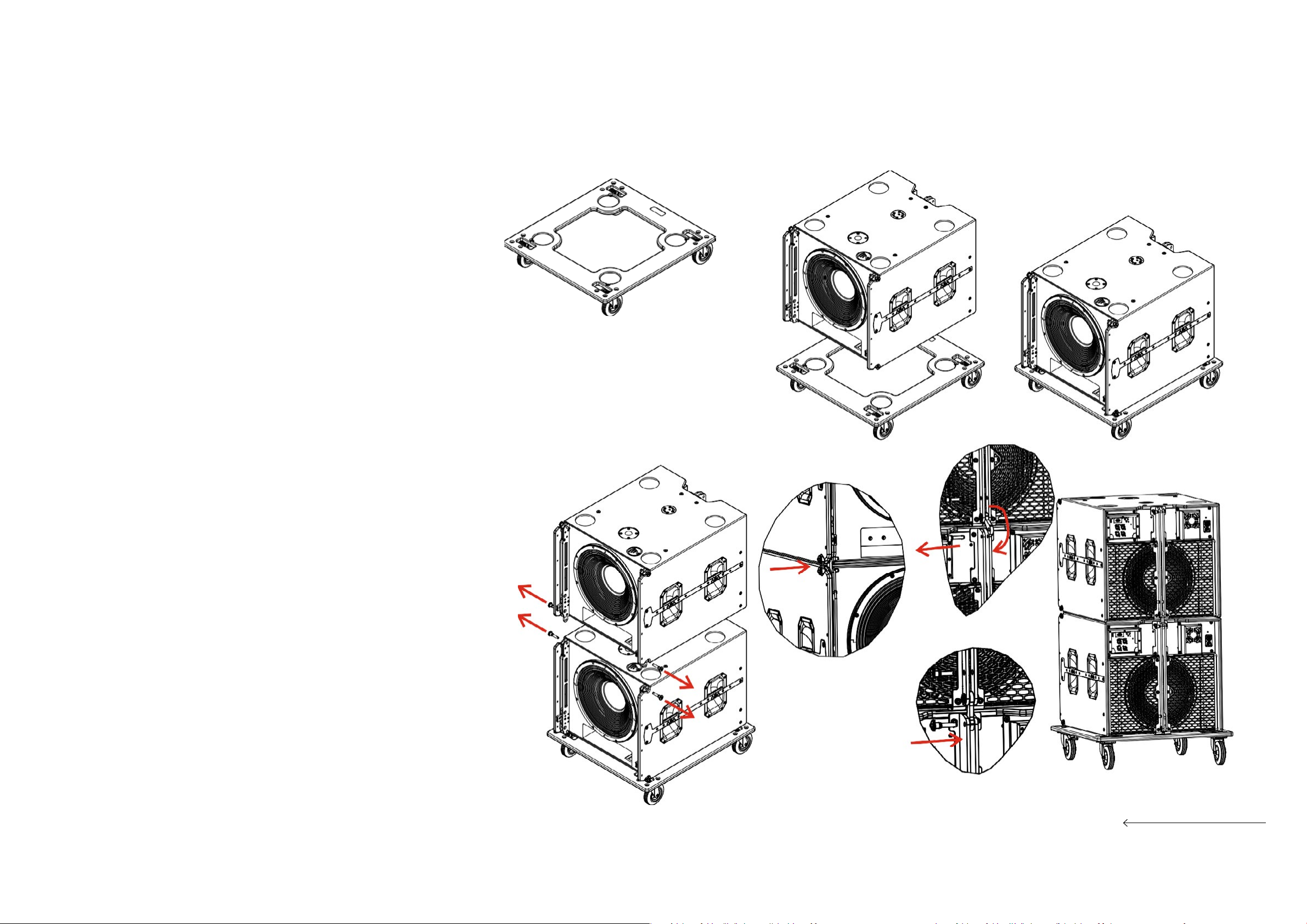
3.- Assembly of a SARA-SUB unit on its transport platform, PL-SARA-SUB.
Disassembly
Fig.1
Only use the PL-SARA-SUB accessory
(WLL160kgf)showninthegureto
stack and transport up to 3 units of
SARA-SUB.
Fig.2
Place the SARA-SUB unit on the
platformaligningitsfeetwiththemarks
on the platform.
Fig.3 y 4
Notethattherstunitisnotattachedto
theplatformwithsecuritypins,however,
subsequent units need to be attached
to each other. Once a unit has been
stacked on top of another unit, insert
the(2)securitypinsonbothsidesatthe
front,asshowningure4.
Fig.5, 6 y 7
Next,removethesecuritypinfromthe
rearplates,lowertherearconnecting
rodandattachitwiththepreviously
removedsecuritypin,asshowninthe
gure.Theresultcanbeseeningure7.
*Tostackathirdunit,followtheabove
described steps
**Todisassemble,followthestepsabove
inreverseorder
Fig.1 Fig. 2
Fig.3
Fig.4
Fig.6
Fig.5 Fig.7

6
SARA manual / SARA - SUB
4.- Assembly of GS-PL-SARA. Angle settings.
Stability, max and min angle and max
number of units
Fig.1
ThegureshowsthePL-SARA(WLL=160
kgf)accessory.
Fig.2
The GS-PL-SARA accessory can be at-
tachedtothePL-SARAtoprovideaddi-
tionalstabilityingroundstackedSARA
(WLL=160kgf)applications.
Fig.3
Thegureshowshowthedifferentparts
oftheaccessorytintothecorrespond-
ingslots,releasingthesecuritylatches
included. Note that the elbow pieces are
mounted at the front of the platform,
whiletheremainingpiecesgoatthe
back.
Fig.4
Note that the maximum number of units
thatcanbegroundstackedremains4.
PL-SARA platforms and the GS-PL-SARA
accessoryaredesignedformaximum
stabilitywitha±14°tiltabovethehorizon-
tal,regardlessofthesplayanglebetween
the4SARAunitsthatcanbestackedon
them.
WhenusingtheGS-PL-SARA,makesure
that the platform and accessories are
mountedonarmsurface.
Fig. 2
Fig. 1
Fig.3 Fig. 4

7
SARA manual / SARA - SUB
Fig.5
Asshowninthegure,thesplayangles
between two adjacent SARA units can
rangefrom0to10degreesmaximum
(thenumbersontherearplatesofthe
SARAunitsindicatethesplayanglesin
degrees).Whenshippedfromthefacto-
ry,theunitshaveasecuritypinstowed
in the “PIN HOLDER” position, inserted
ontherightsideoftheirrearplate,and
another pin stowed in the “STORE LINK”
position, inserted on the left. Insert the
rstpininthedesiredsplayangleandin-
serttheotherpintolocktheconnecting
rodinthechosenangleplus1.Thatis,ifthe
desiredangleis4degrees,insertthe“PIN
HOLDER”pininhole“4”andthe“STORE
LINK” pin in hole “5”. When the de-
siredangleis10degrees,insertthe“PIN
HOLDER”pininhole“10”,andthe“STORE
LINK”pinintheholemarked“10+1”.Make
suretheconnectingrodfromtheunit
ontopisttedbetweentherearplates
of the unit below to ensure the two units
are securely attached.
4.- Assembly of GS-PL-SARA. Angle settings.
Stability, max and min angle and max
number of units

8
SARA manual / SARA - SUB
5.- Assembly of 4 SARA units with TOP-PL-SARA on platform
Fig.1
StacktherstSARAunitontheplatform
aspreviouslydescribedinthismanual.
Toattachthefollowingunit,removethe
top security pins of the bottom unit.
Alignthetwounitsandremovethetwo
bottom security pins of the upper unit.
Lowertheconnectingrodsandmake
suretheholesarealignedcorrectly.
Fig.2
Re-insert the four security pins to attach
the two SARA units at the front.
Fig.3
Now, it is time to attach the back of the
unit.
Fig.4
Removethesecuritypinthatlocks
therearconnectingrodandlowerthe
connectingrodfromtheupperunit.
Fig.5
Attachtheconnectingrodwiththe
securitypinandremovethesecuritypin
from the bottom unit.
Fig.6
Insertthispinintothefollowinghole
usedbytherstpin,asshowninthe
gure.
Fig.1 Fig. 2
Fig.3 Fig.4 Fig.5 Fig.6

9
SARA manual / SARA - SUB
Fig.7
Follow the same steps to stack further
units,theresultcanbeseeninthegure.
Fig.8
Rearview.
5.- Assembly of 4 SARA units with TOP-PL-SARA on platform
Fig.7 Fig. 8

10
SARA manual / SARA - SUB
Fig.9
Fig.12
Fig.9
To attach the TOP-PL-SARA to the unit on
top,rst,removethetwouppersecurity
pins from the SARA unit.
Fig.10
LowertheTOP-PL-SARA,aligntheholes
and attach with the two security pins.
Fig.11
AligntheTOP-PL-SARArearbracketwith
the last hole on the SARA rear plate.
Fig.12
Removethesparepinstowedontherear
plates of the SARA unit and attach the
unit to the TOP-PL-SARA with it.
Fig.13
Insert the pin into the hole of the TOP-PL.
Fig.14
The stack with the accessory can be seen
inthegure.
5.- Assembly of 4 SARA units with TOP-PL-SARA on platform
Fig. 10
Fig.12
Fig.11
Fig.13 Fig.14
Fig.9
Table of contents
Other DAS AUDIO Speakers manuals


