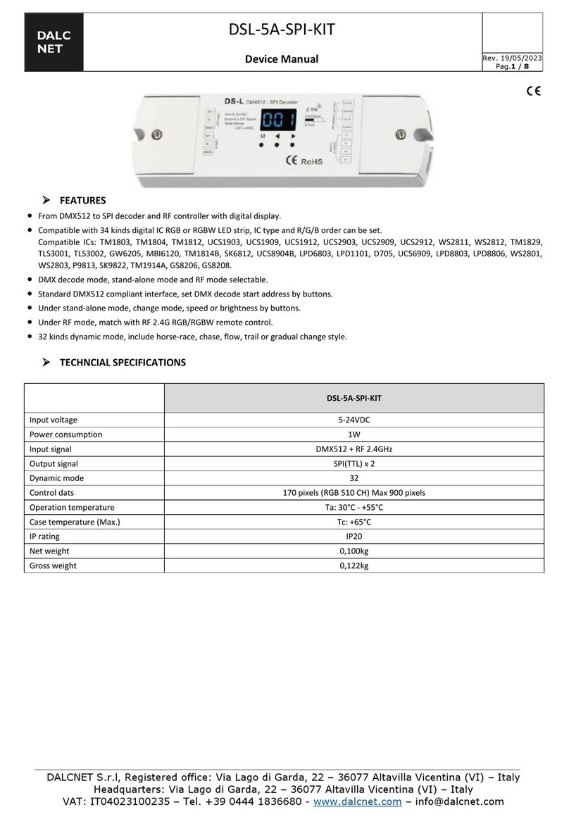
Dasko Electronic DSS2 T-BIS_P User manual

DSS2 T-BIS –THE MICROPROCESSOR, TRIAC BASED SPEED CONTROLLER –MANUAL v.2.6 / II-2017
DASKO Electronic ul. Do Studzienki 34B, 80-227 Gdańsk /Poland/ tel: (+48) 58 3459107
info@dasko.pl www.dasko.pl
1/4
1. DESCRIPTION
Microprocessor, triac-based speed controller for 1-phase motors
DSS2 T_BIS is available in two versions:
DSS2 T_BIS –controlled by 0-10V analog signal (Fig.1)
DSS2 T_BIS_P –controlled by 0-10V analog signal or keypad placed
on the facade (Fig. 2)
Fig. 1. DSS2 T-BIS_P
Fig. 2. DSS2 T-BIS_P
2. APPLIANCE
The DSS2 ECO-1.5 speed regulators are designed for voltage speed control
of single-phase motors.
Typical motors suitable for voltage control:
motors with start up capacitor,
motors with work capacitor,
commutator motors.
WARNING! 1-phase asynchronous motors cannot be controlled by DSS2
T-BIS speed regulator. You should always make sure that the motor is
suitable for voltage control.
Typical DSS2 T-BIS applications:
air handling units and recuperator fans,
heating units fans (water heaters, electric heaters),
small electromechanical equipment, lighting, etc.
3. TECHNICAL DATA
Table 1. Technical data of DSS2 T-BIS speed controller
MODEL
DSS2 T-BIS
DSS2 T-BIS_P
Supply voltage
230V / 50Hz
Max continuous current
5 A
Max peak current
8 A
Rated load
1,0 kW *
Steering
0-10 V signal
keypad / 0-10 V
IP protection level
IP 54
Mounting
surface / plate mounted
Signalling
–
on keypad
Steering type
Phase angle, triac
PWM frequency
50 Hz
Operating temperature range
-10÷50oC
Storage temperature range
-30÷60oC
0-10V analog input
Impedance of 25 kOhm, galvanically
isolated from the power supply
Additional voltage source
Supply source of 16 VDC, 15 mA
Housing material
ABS
Dimensions (HxWxL)
56x84x124 mm
Weight
410 g
* given power is an estimate - a key parameter for the selection of the
controller is the receiver’s current
4. CHARACTERISTIC FEATURES
Smooth adjustment of the output voltage over the whole control
range.
Bimetallic contact motor protection control. Stop of work and alarm
indication.
Possibility to change the controller’s settings.
Adjustable output voltage depending on the setpoint of the keypad or
an external 0-10V signal level.
Possibility to combine multiple controllers in systems and control
them from a single point.
Compact, small and ergonomic design.
5. INSTALLATION
The DSS2 T-BIS speed controller should be mounted horizontally on
the surface of a wall or in the control cabinet (in this case the
exchange of air or cooling should be made).
The power must be connected with non-shielded 3x1 mm² cable.
Steering signal must be connected by the shielded cable:
2x0.5 mm² – for steering by DEN 20, DEN30, PLC etc.
3x0.5 mm² – for steering by DEN 11.
The cable shield should be connected to G0 terminal.
The motor must be connected with the shielded 3x1 mm² cable.
The shield must be connected to the PE terminal and the motor
housing.
Cables must be completed with sleeves.
To connect the wires unscrew the four screws that secure the lid and
then perform the connection according to the diagram in Figure 4.
After connections are made, close the cover and switch the power
supply on.
The capacitor should be connected outside of the regulator.
The regulator provides an additional input to TK fan protection.
It must be connected by 2x1 mm² cable.
WARNING!
It is essential to disconnect the power before installing the
product.
It is forbidden to run the controller with an open case.
Installation should be performed by qualified personnel or the
service.
Non-authorised changes lead to warranty loss.
It is forbidden to disconnect the load (the motor) while operating.
By doing so you may damage the controller!
If the T5 fuse blows it is recommended to try to run a regulator
with an inserted F400 fuse and disconnected motor. If the fuse
does not blow - insert the T5 fuse and start the controller. If the
fuse blows again, please contact the manufacturer.

DSS2 T-BIS –THE MICROPROCESSOR, TRIAC BASED SPEED CONTROLLER –MANUAL v.2.6 / II-2017
DASKO Electronic ul. Do Studzienki 34B, 80-227 Gdańsk /Poland/ tel: (+48) 58 3459107
info@dasko.pl www.dasko.pl
2/4
6. OPERATION
6.1. Operating mode selection
On the speed controller’s board there is a SW1 switch by which you can
choose the control type - with the keypad (D mode) or 0-10V signal (mode
A). Switching must be done in OFF state in accordance with the Fig. 4.
6.2. Keypad based control (D mode)
The DSS2 T-BIS_P regulator keypad (Fig. 3) is placed on the facade.
It allows using all the features of the device without the need for external
controllers and to monitor the current state of work.
Fig. 3. DSS2 T-BIS control keypad.
(1) –ON/OFF button, (2) –DOWN button, (3) –UP button
(4) –LED indicator bar, (5) –work and alarm LED indicator
To switch the regulator on press the ON/OFF button. The regulator starts
and you can change the output voltage with the DOWN and UP buttons.
The steering level is indicated by a LED indicator bar consisting of 8 LEDs.
Pressing the ON/OFF button again stops the regulator. The fan slows
down smoothly, which is signalized by blinking of a LED indicator bar.
If the power is disconnected during work and then is connected again, the
regulator will start working with the last memorized fan speed.
6.3. Analog 0-10V signal based control (A mode)
0-10V analog input allows setting the fan speed remotely. It is possible to
connect regulators into systems controlled by a single signal set by an
external controller.
The regulator is equipped with its own source of +16 VDC voltage supply,
which can be used to power the DEN10 or DEN11 controller.
In DSS2 T-BIS_P signalling of work, alarm and speed level is done through
LEDs in the same way as for the control by the keypad. ON/OFF button
allows you to stop and resume work. Buttons DOWN and UP do not affect
the operation of the device in A mode.
In DSS2 T-BIS there are no buttons or indicator LEDs.
6.4. TK alarm indication
The red LED indicates ALARM of motor overheating. It is detected by
thermocontact switch opening. The regulator turns the engine off. After
the engine has cooled, the alarm LED flashes for 10 seconds and the
engine switches on again.
The alarm is displayed only on the regulator’s keypad. A regulator without
a keypad does not have a LED alarm signaling.
7. SERVICE MODE
The service mode allows adjusting the parameters of the regulator to the
individual user needs. The following parameters can be modified:
minimum output level, maximum output level, minimum analog 0-10V
value, maximum analog 0-10V value and K1 contactor operation mode.
7.1. Entering and navigation in the service mode
To enter the service mode the regulator must be in operation mode (the
LED "RUN" is lit). Simultaneously press and hold UP and DOWN buttons
for 6 seconds. The moment of entering the service mode is indicated by
the LED line blinking.
After entering the service mode, the 1st menu level is selected –
parameter selection mode. DOWN and UP buttons allow selecting the
parameter to edit. The currently selected parameter is indicated by the
corresponding LED in LED line (from No. 1 to No. 6). After making your
selection by pressing the ON/OFF button, the regulator goes into the 2nd
menu level –parameter edit mode. This state is indicated by blinking of
the green RUN LED.
The flashing LED indicates the parameter number, which is currently
edited. The number of LED’s lit in the LED line indicates the parameter’s
current value on the scale of 0-100% or the currently selected option.
To edit the parameter’s value use DOWN and UP buttons (except for Amin
and Amax settings). To accept the changes press the ON/OFF button to
make the changes and return to the 1st menu level.
After editing in order to save the set values and to leave the service mode,
press simultaneously DOWN and UP buttons in the 1st menu level. The
LED line will blink and the regulator will turn off. After turning the
regulator on again it will work according to the modified parameters.
WARNING! Any changes made to the parameters are stored in EEPROM
only after exiting the service mode using keys DOWN and UP in the
manner described above.
7.2. Parameter description and editing
WARNING! The DSS2 T-BIS type regulators do not have the function to
restore the factory default settings. Settings changes must be made with
caution!
1
2
3
4
5

DSS2 T-BIS –THE MICROPROCESSOR, TRIAC BASED SPEED CONTROLLER –MANUAL v.2.6 / II-2017
DASKO Electronic ul. Do Studzienki 34B, 80-227 Gdańsk /Poland/ tel: (+48) 58 3459107
info@dasko.pl www.dasko.pl
3/4
LED No. 1, Parameter: Mode
Work mode selection
After entering the edit mode, the "RUN" LED and No.1 LED blinks. Lighting
up LEDs no. 2-7 indicates the mode selection:
LED 2 –A mode –0-10V control; basic, non-linear characteristic;
Dmin / Dmax control,
LED 3 –Ax mode –0-10V control; improved, linear characteristic;
lack of Dmin / Dmax control,
LED 4 –D mode –keypad regulation; basic, non-linear characteristic;
Dmin / Dmax control,
LED 5 –Dx mode –keypad regulation; improved, linear characteristic;
lack of Dmin / Dmax control,
LED 6 –Dm mode –the same as D mode, with drive speed setpoint
memory
LED 7 –Dmx mode –the same as Dx mode, with drive speed setpoint
memory
In the D and Dx modes turning the regulator off resets the drive speed
setpoint. After turning the regulator on you must set the new setpoint
manually. In Dm and Dmx modes the setpoint is saved in the memory –
the regulator continues to work with the previously set speed.
In modes with improved (linear) work characteristics –Ax and Dx –there
is no possibility to adjust the minimum and maximum output voltage of
the regulator. The regulation is always carried out in the range of 0-100%.
LED No. 2, Parameter: Dmin
Adjusting the minimum regulator output voltage corresponding to the
minimum steering level
WARNING! While editing the parameter, the regulator constantly supplies
power to the motor! Its value is changed by holding the UP or DOWN
button.
The LED bar indicates the parameter’s values in the range of 0-100%. Each
LED light increases Dmin value by about 12.5%. By default, there is one
LED bar diode lit (12.5%).
WARNING! Dmin parameter allows you to change the minimum value of
the output voltage during operation of the regulator (steering level higher
than zero). At the setting of 0% steering level, the regulator always
switches the motor off.
LED No. 3, Parameter: Dmax
Adjusting the maximum regulator output voltage corresponding to the
maximum steering level
WARNING! While editing the parameter, the regulator constantly supplies
voltage to the motor! Its value is changed by holding UP or DOWN button.
The LED bar indicates the parameter values in the range of 0-100%. Each
LED light increases Dmin value by about 12.5%. By default, there is all LED
bar diode lit (100%).
LED No. 4, Parameter: Amin
Adjusting the minimum voltage of 0-10V signal resulting in the regulator
activation (threshold).
The parameter can be adjusted in the range of 0 –12.5 VDC.
The factory default setting is 0.3 V.
To set the parameter value –see Amax parameter description.
LED No. 5, Parameter: Amax
Adjusting the maximum voltage of 0-10V signal resulting in the full
activation of the regulator
The parameter can be adjusted in the range of 0 –12.5 VDC.
The factory default setting is 10 V.
After entering the edit mode of Amin or Amax parameter the "RUN" LED
and LED 3 or 4 blinks. The LED line indicates the current voltage applied to
the analog input on the scale 0 –12.5 VDC.
Amax and Amin parameter changes are made not by editing, but by
saving the current voltage level applied to the analog input of the
regulator.
For this purpose, in Amin/Amax edit mode you should set the control
voltage at the desired value to the DSS2 T-Bis analog 0-10V input (AI, G0
connectors), and then confirm the selection by pressing the ON/OFF
button. The current level of the control voltage is stored and used as the
new value of Amin or Amax.
WARNING! By entering and exiting Amin or Amax parameter editing
mode without setting the appropriate control input voltage level, the
regulator will remember no voltage level (0 V) as the value of Amin or
Amax. This may result in the incorrect operation of the regulator in
A mode.
In this case reset the desired voltage Amin/Amax levels correctly.
In case of accidental entry into editing of parameter 4 or 5 with no
intention of modifying it, it is advisable not to leave the regulator’s service
menu, but to disconnect it from the power supply, as any changes made in
the service mode are saved to the EEPROM only when exiting from this
mode.
LED No. 6, Parameter: Ko
Selecting the mode of action of the K1 relay
When you enter the parameter edit mode the "RUN" LED and the LED
No. 6 blinks. The current state of the parameter is indicated by LED No. 2.
OFF –No. 2 LED is not lit –the relay will operate in the "on / off"
mode –the power line of U1_OUT will be turned on when steering is
greater than 0% and shut down when set to 0%.
ON –No. 2 LED is lit –the relay will operate in the "always on" mode.
After the first turn on the relay will no longer disconnect the power
line from U1_OUT output, even when steering signal is set to 0%.
The default setting is "OFF" –"on / off" operation mode.

DSS2 T-BIS –THE MICROPROCESSOR, TRIAC BASED SPEED CONTROLLER –MANUAL v.2.6 / II-2017
DASKO Electronic ul. Do Studzienki 34B, 80-227 Gdańsk /Poland/ tel: (+48) 58 3459107
info@dasko.pl www.dasko.pl
4/4
8. ELECTRICAL CONNECTIONS AND DIMENSIONS
WARNING! Pay special attention to the connection of the regulators
power cord (L, PE, N). Connecting inconsistent to the description (e.g.
replacing "L" with "N") can lead to the appearance of the voltage at the
motor terminals, despite the fact that the regulator main switch is set to
an off position!
Fig. 4. DSS2 T-BIS and DEN11 connection diagram
Fig. 5. Connection diagram of the motor with work capacitor
Fig. 6. Dimensions of DSS2 T-BIS
This manual suits for next models
1
Popular Controllers manuals by other brands
Sunlover
Sunlover SL8-RTA instructions
Brink
Brink Air for life Installation regulations
SMC Networks
SMC Networks LEFS 16 Installation and maintenance manual
YASKAWA
YASKAWA PROFINET V1000 installation manual
Leroy-Somer
Leroy-Somer UMV 2301 AS Series Installation and Maintenance

CTA
CTA PAD-BTC instruction manual
