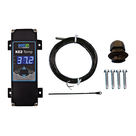
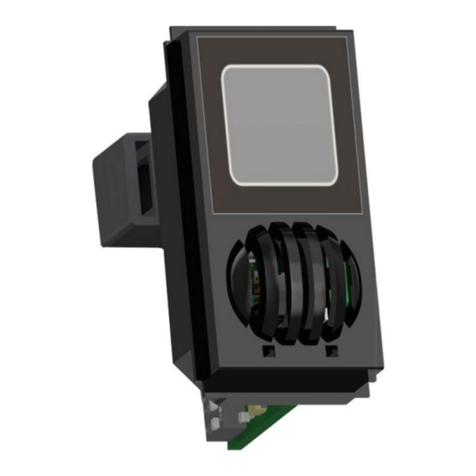
Data Flow Systems TCU800 User manual

T C U 8 0 0
Quick Start Guide
Data Flow Systems, Inc.

NOTICE
Data Flow Systems, Inc. assumes no responsibility for any errors that may appear in this document, nor
does it make any commitment to update the information contained herein. However, questions regarding
the information contained in this document are welcomed.
Data Flow Systems, Inc. also reserves the right to make changes to the specifications of the Telemetry
Control Unit and to the information contained in this document at any time without notice.
© Data Flow Systems, Inc.
605 N. John Rodes Blvd., Melbourne, FL 32934
Phone 321-259-5009
Fax 321-259-4006
www.dataflowsys.com
DFS-00540-011-01
This document last updated October 29, 2020.

2
This document provides a brief overview of the TCU’s features and sufficient information to get the unit
mounted and powered in pump controller mode. Throughout this manual, the name “TCU” will refer to
specifically the TCU800 and NOT its predecessor the TCU001.
Detailed information on wiring the I/O, and configuring and using the TCU800 can be found in the TCU800
Installation and Operation Manual (see DFS website for the PDF version of this manual).
This quick start guide and other manuals can be found on Data Flow Systems’ web site at
www.dataflowsys.com.
This information is provided for qualified personnel only.
Improper installation, service, or maintenance can cause property damage, injury, or death.
Read the installation and operating instructions thoroughly before installing or servicing
this equipment.
Precautionary measures must be observed when installing, operating, and servicing the
TCU in order to prevent shock from voltages present.
If the TCU is to be installed into an existing control panel, make sure that all breakers are
shut off before starting the installation.
All wiring must conform to federal, state, and local electrical codes.

3
Description
The Telemetry Control Unit (TCU) Model TCU800 is a highly-integrated pump controller running an
embedded Linux operating system. It is designed to be completely backward compatible with its
predecessor (TCU001) while also including additional feature enhancements to expand its operability.
There are several options for using the TCU's multiple input and output points.
• They can be used as non-intelligent I/O by setting the number of pumps to 0.
• They can be used in a pump control application.
• They can be manipulated logically with custom software (much like a PLC).
Additionally, the TCU:
• Can communicate with and manipulate the I/O of up to 15 remote modules via a radio or network
link.
• Can be incorporated into a Remote Terminal Unit (RTU) by using a Bus Extender Module
(BEM).
The installed pump control application program enables the TCU800 to be easily implemented in lift station
or storage tank applications. For a pump control application, the TCU800 contains all the hardware and
software needed to control up to three motor starters.
Placing custom software on the TCU800 enables it to perform a variety of automated tasks when interfaced
with other telemetry equipment (DFS equipment, or RS-485 or RS-232 Modbus compatible devices). When
used as a programmable device, the TCU800 can control up to 6 digital output devices, and monitor up to
18 digital and 4 analog input devices. It also features an expansion card slot on the top side which can be
used to add additional I/O for specialized applications.
The TCU's dual functionality (its ability to use the built-in pump control process or a custom program)
helps reduce overhead by enabling one unit to be used in either a pump control or programmable
application.
Parts List
• TCU800 with integrated radio
• Installation kit
Receipt of Equipment
When the equipment is received, examine the outside of the carton for any damage incurred during
shipment. Remove the packing list and the equipment from the shipping carton. Carefully inspect the
equipment for damage. Resolve any damage with the local carrier. Report damages to Data Flow Systems
via phone at 321-259-5009. Include the serial number of the unit and the extent of damage in your report.
Technical Specifications
• Box Dimensions: 5.75” X 8.75” X 5.45”
• Supply Voltage: 120VAC +/-10%, 60 Hz
• Supply Current: 0.5-1.5A
• Processor Core: AM335x SoC with an ARM Cortex A8 (1GHz) + dual PRU (200MHz); 512MB
DDR3 and 4 GB onboard flash

4
• Internal Phase Monitor: 240 VAC @ 60Hz single- or three-phase; 480 VAC @ 60Hz three-phase
using external resistors
• Battery Backup: 12-volt, sealed, lead-acid battery
• Analog Inputs: (3) 4-20mA @ 250Ω/ 0-5VDC or 0-10VDC @ 120KΩ, 15-bit
4-20mA @ 250Ω, 15-bit precision
• Digital Inputs: (17) 10-30V @ 6KΩ/ 30-300V with external resistors
10-30VDC / pulse input <1000 PPS
• Digital Outputs: (4) Solid State Relays, 120-240VAC @ 60Hz, 1A, Pilot Duty
• Alarm Relays: (2) Electromechanical Relays, 120VAC @ 60Hz, 0.5A / 0-24VDC, 1.0A; NO
(Alarm Horn), NC (Alarm Light)
• Integrated Radio: 2W @ 200 MHz or 5W @ synthesized 400 MHz
• RS-232 Interface: 9600-115200 baud serial interface for Modbus ASCII devices (RTU protocol
option available)
• RS-485 Interface: 9600-115200 baud serial interface for Modbus ASCII/RTU devices
• Ethernet Interface: 10/100base-T
• USB 2.0 (Full Speed): 2 ports external, 1 port internal
• Isolated 24VDC Bias: 300 mA current limited and regulated
• Input Protection: MOV (Metal Oxide Varistor), TVS (Transient Voltage Suppressor), and on-chip
transformer isolation
• 5” TFT LCD w/ capacitive touchscreen and overlay push-button
• H-O-A Switches: 3 x 3-position switches for Hand-Off-Auto operation
• Environmental Conditions:
• Ambient Operating Temperature Range: -10°C to 60°C (14°F to 140°F). The upper
temperature limit is 50°C (122°F) when using the recommended backup battery.
• Relative Humidity: 0-100%
• Atmospheric Pressure: 75-106 KPa
• Overvoltage Category II
• Pollution Degree 2
• Safety Approval: UL listed for Process Control Equipment (UL1092)
Features
• Backward compatibility with Data Flow Systems’ TAC Pack TCU001
• Integrated 10/100 network adapter to allow remote access via SSH client over a local area
network
• Eighteen (18) isolated digital inputs for monitoring level (float switches) or contact closures
• Four (4) 15-bit isolated analog inputs offer enhanced accuracy, range, and increased resolution
• Six (6) digital outputs: Three motor start outputs, one auxiliary output, and two for controlling an
alarm horn/light
• Integrated digital radio (2W, 200 MHz or 5W, 400MHz) is on-site programmable and can run in
legacy (Manchester) or high-speed mode
• ARM based core running Linux Debian allows easy programming and configuration via terminal
• True RMS AC phase monitor produces accurate voltage readings for single- and three-phase
power

5
• RS-485 Modbus fieldbus half-duplex serial interface enables communication with industry
standard devices and VFD motor controllers
• Configurable, auxiliary digital input can be used with pulse-type flow meters and rain gauges
• Standard RS-232 Modbus radio interface acts as an interface to external industry standard radios
• TX/RX/Status LEDs and LCD Touchscreen indicate operating I/O state
• Three fail-safe Hand-Off-Auto (HOA) switches
• Four connectorized wire terminals and USB configuration stick allow servicing or replacement of
the unit without rewiring the control panel
• 5” LCD provides a large area for displaying data, and the LCD's brightness can be changed via
settings and allows for a day- or night-mode display of screens to enhance visibility in either
direct sunlight or at night
• Home button/soft-power switch offers ease of use when powering up/down the TCU
• Self-monitoring capabilities include an ON state self-test and monitoring of radio current and unit
temperature
• For each pump, elapsed run time and average run time meters are provided
• HyperTAC 4 telemetry interface enables operators to remotely monitor off-site conditions and
control equipment from a central location
• Mounting options allow the TCU to be mounted to a front panel, or mounted flush against or
stood off from the back plate of a control panel
• Integrated switching power supply
• Surge protection (non-destructive) and on-board voltage regulation
• Battery backup with external battery (12V, 2.6Ah or 12V, 7.0Ah)
• Can be programmed using ladder logic via DFS’ Virtual Logic Builder
Pin Name / Wiring Definitions
The tables below and on the next several pages provide pin names and descriptions for a TCU using the
built-in pump controller application.
Pin Outs for Pump Controller Application
Top Front Connector: P1 (Pump Controller Mode)
PIN#
Name
Description
Electrical Rating
P1-1
PHASE_C
Phase C of the three-phase power monitor
120-240VAC, 60HZ,
10mA, 3-phase
P1-2
PHASE_B
Phase B of the three-phase power monitor
120-240VAC, 60HZ,
10mA, 3-phase
P1-3
PHASE_A /
PHASE_N
Phase A of the three-phase power monitor in
3-Wire (delta)
Neutral of the three- phase power monitor in
4-Wire (wye)
120-240VAC, 60HZ,
10mA, 3-phase
P1-4
PHASE A
Phase A of the three- phase power monitor in
4-Wire (wye) only.
120-240VAC, 60HZ,
10mA, 3-phase
P1-5
AC_PWR
AC power
120VAC, 60HZ, 0.5-1.5A
P1-6
AC_NEUT
AC neutral
120VAC, 60HZ, 0.5-1.5A
P1-7
TGND
Safety ground (Earth)
Ground

6
P1-8
BAT+
Backup battery positive terminal
<24V / Not Rated
P1-9
BAT-
Backup battery negative terminal
<24V / Not Rated
P1-10
BEMGND
Isolated ground (wire to BEM001, pin 12)
<24V / Not Rated
P1-11
BEM_PWR
Isolated power (wire to BEM001, pin 10)
<24V / Not Rated
P1-12
BEM_CTS
Isolated clear to send (wire to BEM001, pin 6)
<24V / Not Rated
P1-13
BEM_RXD
Isolated receive data (wire to BEM001, pin 4)
<24V / Not Rated
P1-14
BEM_TXD
Isolated transmit data (wire to BEM001, pin 2)
<24V / Not Rated
P1-15
BEM_RTS
Isolated request to send (wire to BEM001, pin
8)
<24V / Not Rated
P1-16
ALM_HORN
Load side of alarm horn relay (NO)
120VAC, 60HZ, 1A,
0-24VDC, 1A
P1-17
ALM_LITE
Load side of alarm light relay (NC)
120VAC, 60HZ, 1A,
0-24VDC, 1A
P1-18
ALM_PWR
Line side of alarm relays
120VAC, 60HZ, 2A,
0-24VDC, 2A
P1-19
AUX_OUT
Load side of auxiliary relay
120-240VAC, 60HZ, 1A,
Pilot Duty
P1-20
AUX_PWR
Line side of auxiliary relay
120-240VAC, 60HZ, 1A
P1-21
MTR3_STR
Load side of motor starter 3 relay
120-240VAC, 60HZ, 1A,
Pilot Duty
P1-22
MTR2_STR
Load side of motor starter 2 relay
120-240VAC, 60HZ, 1A,
Pilot Duty
P1-23
MTR1_STR
Load side of motor starter 1 relay
120-240VAC, 60HZ, 1A,
Pilot Duty
P1-24
STRT_PWR
Line side of motor starter relays
120-240VAC, 60HZ, 3A
Top Rear Connector: P3 (Pump Controller Mode)
PIN#
Name
Description
Electrical Rating
P3-1
C_CT+
C-phase current transformer positive connection
<24V / Not Rated
P3-2
C_CT-
C-phase current transformer negative connection
<24V / Not Rated
P3-3
B_CT+
B-phase current transformer positive connection
<24V / Not Rated
P3-4
B_CT-
B-phase current transformer negative connection
<24V / Not Rated
P3-5
A_CT+
A-phase current transformer positive connection
(wye setup only)
<24V / Not Rated
P3-6
A_CT-
A-phase current transformer negative connection
(wye setup only)
<24V / Not Rated
P3-7
ANALOG3+
0-5VDC or 0-10VDC or 4-20mA signal from
transducer; return signal at P3-8; jump
P3-9 to P3-8 to use as a
4-20mA input
<24V / Not Rated
P3-8
ANALOG3-
- return signal for ANALOG3+ (P3-7)
<24V / Not Rated
P3-9
SHUNT
250Ωshunt resistor; jump to P3-8 to use a
4-20mA signal for ANALOG3+ (P3-7)
<24V / Not Rated
P3-10
ANALOG4+
0-5VDC or 0-10VDC or 4-20mA signal from
transducer; return signal at P3-11; jump P3-12 to P3-
11 to use as a 4-20mA input
<24V / Not Rated
P3-11
ANALOG4-
- return signal for ANALOG4+ (P3-10)
<24V / Not Rated
P3-12
SHUNT
250Ωshunt resistor; jump to P3-11 to use a 4-20mA
signal for ANALOG4+ (P3-10)
<24V / Not Rated

7
P3-13
SHIELD
Internally connected to EARTH; cable shield for
analog monitor signals
Ground
P3-14
IN_COM_3
Common return for thermal and seal failure digital
inputs
10-30VAC/DC,
100mA RTN
P3-15
MTR3_THERM
Motor 3 temperature monitor input
10-30VAC/DC,
10mA
P3-16
MTR2_THERM
Motor 2 temperature monitor input
10-30VAC/DC,
10mA
P3-17
MTR1_THERM
Motor 1 temperature monitor input
10-30VAC/DC,
10mA
P3-18
MTR3_SEAL
Motor 3 moisture seal monitor input
10-30VAC/DC,
10mA
P3-19
MTR2_SEAL
Motor 2 moisture seal monitor input
10-30VAC/DC,
10mA
P3-20
MTR1_SEAL
Motor 1 moisture seal monitor input
10-30VAC/DC,
10mA
Bottom Front Connector: P2 (Pump Controller Mode)
PIN#
Name
Description
Electrical Rating
P2-1
MTR1_RUN
Motor 1 run digital monitor input
10-30VAC/DC,
10mA
P2-2
MTR2_RUN
Motor 2 run digital monitor input
10-30VAC/DC,
10mA
P2-3
MTR3_RUN
Motor 3 run digital monitor input
10-30VAC/DC,
10mA
P2-4
EXT_PM
External phase monitor digital input
10-30VAC/DC,
10mA
P2-5
IN_COM_1
Common return for motor run and external phase
monitor input
10-30VAC/DC,
100mA RTN
P2-6
LOW_LVL
Low Level digital monitor input
10-30VAC/DC,
10mA
P2-7
OFF_LVL
Off Level digital monitor input
10-30VAC/DC,
10mA
P2-8
LEAD_LVL
Lead Level digital monitor input
10-30VAC/DC,
10mA
P2-9
LAG1_LVL
Lag1 Level digital monitor input
10-30VAC/DC,
10mA
P2-10
LAG2_LVL
Lag2 Level digital monitor input
10-30VAC/DC,
10mA
P2-11
HIGH_LVL
High Level digital monitor input
10-30VAC/DC,
10mA
P2-12
AUX_IN
Auxiliary digital monitor input; supports pulse counting
10-30VDC, 10mA
P2-13
ALM_SIL
Alarm Silence Switch digital monitor input
10-30VAC/DC,
10mA
P2-14
IN_COM_2
Common return for input level, aux inputs, and alarm
silence switch
10-30VAC/DC,
100mA RTN
P2-15
ISOGND
Internally supplied 24VDC bias source return (isolated)
<24V / Not Rated
P2-16
ISO+24V
Internally supplied 24VDC bias source voltage
(isolated)
<24V / Not Rated

8
P2-17
TXD_232
RS-232 transmit data to external device
<24V / Not Rated
P2-18
RXD_232
RS-232 receive data from external device
<24V / Not Rated
P2-19
GND
RS-232 ground
<24V / Not Rated
P2-20
SHIELD
Internally connected to EARTH; cable shield for analog
monitor signals
Ground
P2-21
ANALOG2+
4-20mA signal from transducer; - signal at pin P2-23;
internal 250Ωshunt permanently connected
<24V / Not Rated
P2-22
ANALOG1+
0-5VDC or 0-10VDC or 4-20mA signal from
transducer; - signal at pin P2-23; jump pin P2-24 to P2-
23 to use as a 4-20mA input
<24V / Not Rated
P2-23
ANALOG-
- signal return for both ANALOG1+ at P2-22 and
ANALOG2+ at P2-21
<24V / Not Rated
P2-24
SHUNT
250Ωshunt resistor; jump to P2-23 to use a 4-20mA
signal for ANALOG1+ at P2-22
<24V / Not Rated
Bottom Rear Connector: P4 (Pump Controller Mode)
PIN#
Name
Description
Electrical Rating
P4-1
Unused
Reserved for future use; do not connect
Not Connected
P4-2
RS485_GND
RS-485 serial ground reference
<24V / Not Rated
P4-3
RS485_B
RS-485 serial interface B
<24V / Not Rated
P4-4
RS485_A
RS-485 serial interface A
<24V / Not Rated
P4-5
SHIELD
Internally connected to EARTH; Cable shield for
RS-485 or RS-232
Ground
P4-6
EX_GND_RAD
RS-232 signal ground
<24V / Not Rated
P4-7
RTS_RAD
RS-232 Request to send
<24V / Not Rated
P4-8
EX_TXD_RAD
RS-232 transmit data to external device
<24V / Not Rated
P4-9
EX_RXD_RAD
RS-232 receive data from external device
<24V / Not Rated
P4-10
CTS_RAD
RS-232 clear to send
<24V / Not Rated
P4-11
SDI12_GND
SDI-12 return/ground
<24V / Not Rated
P4-12
SDI12_DATA
SDI-12 data
<24V / Not Rated
P4-13
SDI12_PWR
12VDC power supply for SDI-12 bus devices
<24V / Not Rated
P4-14
Unused
Reserved for future use; do not connect
Not Connected
Safety Precautions
Review the following statements before installing, servicing, or replacing the Telemetry Control Unit or
any of its components.
General Precautions
• Only trained and qualified personnel should install, service, or replace this equipment.
• Carefully read the installation and wiring instructions before connecting the TCU to its power
source.
• Do not work on the TCU, or connect or disconnect any of its cables, during periods of lightning
activity.
• To prevent overheating the TCU, do not operate it in an area that exceeds the maximum
recommended temperature of -10°C to 60°C (14°F to 140°F). The upper temperature limit is
50°C (122°F) when using the recommended backup battery.

9
• Ensure that the unit is connected to earth ground during normal use.
• Precautionary measures must be observed when installing, operating, and servicing the TCU in
order to prevent shock from voltages present.
• If the TCU is to be installed into an existing control panel, make sure that all breakers are shut off
before starting the installation.
• All wiring should conform to federal, state, and local electrical codes.
• Read and follow all precautionary procedures that are displayed on TCU’s side-mounted labels.
Working with the TCU
Before working with the TCU, specifically when removal of the unit is necessary, perform the following
steps in the sequence indicated:
1. Power down the unit.
2. Turn off all circuit breakers to the TCU.
3. Ensure that any cables connected to the TCU will not become entangled in or caught on anything in
the surrounding area.
When disconnecting a cable, pull on its connector or on its strain-relief loop, not on the cable itself. Some
cables have a connector with locking tabs; when disconnecting this type of cable, press in on the locking
tabs before disconnecting the cable. When pulling connectors apart, keep them evenly aligned to avoid
bending any connector pins. Also, before connecting a cable, make sure both connectors are correctly
oriented and aligned.
Protecting Against Electrostatic Discharge
Static electricity can harm delicate components inside the TCU. To prevent static damage, put on an
electrostatic discharge wrist strap before touching any of the TCU’s electronic components.
In addition to the preceding precautions, the following steps can be taken to prevent damage from
electrostatic discharge (ESD):
• When unpacking a static-sensitive component from its shipping carton, do not remove the
component's antistatic packing material until ready to install the component in the TCU. Be sure
to put on an electrostatic discharge wrist strap before unwrapping the antistatic packaging.
• When transporting a sensitive component, first place it in an antistatic container or packaging.
• Handle all sensitive components in a static-safe area. Place the equipment on a grounded surface.
If possible, use antistatic floor pads and workbench pads.
Note: Contact DFS if electrostatic discharge packaging is needed for return shipments. See Return
Authorization (RA) Procedure on page 29 for more information on returning equipment.
Using the TCU
When using the TCU, observe the following safety guidelines:
• To help prevent electric shock, wire the TCU and peripheral power cables into properly grounded
power sources.
• Be sure nothing rests on the TCU’s cables and that the cables are not located where they can be
stepped on or tripped over.
If the TCU’s LCD Screen or Status LED is not lit, you should assume that the TCU is still powered. This
indicates that the TCU is in the off state, not that AC power has been removed. To remove power, you
must turn off the external circuit breaker.

10
Installation
Site Selection
When selecting a site for the TCU, keep the following in mind:
• The TCU requires a 120 VAC power supply.
• The TCU is designed to operate at a recommended temperature range of -10°C to 60°C (14°F to
140°F). The upper temperature limit is 50°C (122°F) when using the recommended backup
battery.
• The TCU is intended to be permanently installed in a NEMA 12 or higher rated panel that
prevents access to live parts without a tool.
• Attention should be given to the location of the TCU to provide accessibility for wiring and
servicing. Leave enough space around the TCU to access the TCU’s fuse and to remove the
connectorized terminal strips. Install the TCU in the panel at a position where the LCD display
can be read comfortably. The LCD is best viewed at slightly below eye level.
Pre-Installation Modification
Use snips, pliers, or a razor to remove the retention
clips from P-connectors.
Once the retention clip is removed, the P-connector
will be able to be used with the TCU800.

11
Mounting Instructions
The TCU is intended to be permanently installed in a NEMA 12 or higher rated panel that prevents access
to live parts without a tool. The TCU can be mounted in a control panel in several different ways. The unit
can be mounted flush to the back plate of the panel, stood off the back plate, or mounted to a front panel.
Mounting brackets are provided with the TCU that can be used to mount it in any of these positions.
Optional connectors to facilitate the various types of mountings are available as shown on page 21,
“Attaching Connectors” and may be specified as described in the TCU800 Installation and Operation
Manual.
Place the TCU800 in the enclosure in the same manner as a TCU001. Do not insert the address strap into
the new TCU800. Station address configuration is done internal to the TCU800. Find a location inside the
TCU enclosure to secure the Configuration USB. This Configuration USB acts in place of the TCU
Configuration Connector, and also houses all station statistics and settings. This allows a TCU800 to be
switched out in a station, but retain all station configurations and run data upon powering on the replacement
TCU800.
Applying power to the TCU800 will turn it on. To safely turn off the TCU800, hold down the Home button
for 5 seconds. To turn the TCU800 on after a safe shutdown, press the Home button once. To force a reset
of the TCU800, hold the Home button for 11 seconds.
TAC Pack Adapter
This mounting option is available when a TCU is replacing a rear-panel mounted PCU. It uses the
preinstalled PCU mounting bracket and brings the TCU to the same level as the PCU it is replacing.
This option uses the Retro installation kit (Basic Install Kit or Full Install Kit).
Snap-In (Back Panel) Mount
The snap-in mount is available for new installations (i.e., TCU is not replacing a PCU). The mounting
bracket is attached to the back of the control panel, and the TCU is snapped into place. With this mounting
option, the TCU can be installed and removed quickly and easily. This option uses the Snap-In Installation
Kit (Basic Install Kit or Full Install Kit).
PCU Front Panel Mount
This mounting option uses a PCU-type mounting bracket that is attached to the front of a control panel.
With this mounting option, the TCU is attached to the mounting bracket with screws instead of being
snapped into place. This option uses the Front Mount installation kit (Basic Install Kit or Full Install Kit).
This dimensional drawing is provided to aid in installation. If a panel cutout is required, the TCU can be
installed with or without edge molding around the front-panel opening. The panel cutout is different for
each mounting configuration. See "Control panel installation with TCU mounted to dead front" and
"Control panel installation with TCU mounted to front panel,” on the next page.
A qualified technician should install the TCU800.
Precautionary measures must be observed when installing, operating, and servicing the TCU800 in order
to percent shock from voltages present.
If the TCU800 is to be installed into an existing control panel, make sure that all breakers are shut off
before starting the installation.

12
Attaching Connectors
The graphic to the right depicts how each of the TCU's three optional connector types can be attached to
the unit. The first option uses the Spring-Clamp Connector Tool, which can be ordered from DFS. See the
TCU800 Installation and Operation Manual for information on ordering connectors and the connector tool.
Control panel installation with
TCU mounted to dead front
Control panel installation with
TCU mounted to front panel

13
Wiring AC Power
The maximum wire size to TCU connectors is 12 AWG.
Use stranded copper conductors only with a minimum rating of 75°C.
The recommended circuit breaker is 10 Amp maximum.
When using connectors with screw-type terminals, tighten screw terminals to a maximum
7 in-lb (.79 Nm).
All AC source power wired to the TCU should be from the same leg of the three-phase
system. (Diagrams in this section show Phase C (L3) being used.)
The LCD screen and Status LED do not indicate that AC power has been removed. Even if
these indicators are not lit, you should assume that the TCU is still powered. To remove
power, you must turn off the external circuit breaker.
The TCU operates from 120 VAC. Verify the input voltage on the TCU’s connector label before wiring.
Three terminals are provided for wiring power:
• P1-5, AC_PWR (AC power)
• P1-6, AC_NEUT (AC neutral)
• P1-7, TGND (earth ground)
Terminal P1-7 is designated Earth or Safety ground. The TCU’s enclosure is also connected to the TGND
terminal. Wire in accordance with Federal, State, and Local Electrical Codes.
The transformer must provide AC neutral. When wiring to a typical three-phase, 4-wire, 240 Volt
transformer that provides AC neutral, refer to “Typical 240 Volt, 4-Wire Transformer” (next page). Refer
to “Typical 480 Volt, 3-Wire Transformer" (next page) when connecting to a typical three-phase, 3-wire
480 Volt transformer with no neutral provided. Note that these diagrams are for typical installations. If
your installation deviates from that shown here, refer to the National Electrical Code® (NEC®)
Handbook.

14
Powering TCU with Typical 240 Volt, 4-Wire Transformer
Powering TCU with Typical 480 Volt, 3-Wire Transformer
General Operating Instructions
This section provides an overview of the TCU’s user interface. For detailed descriptions and instructions
on use, refer to the TCU800 Installation and Operation Manual, which can be found on the DFS website
(www.dataflowsys.com).
Home Button and Power Indicator
Press and hold the TCU’s home button to turn the unit on or enter a “soft off” state. The LCD screen
indicates the state (on or off) of the TCU800. When turning the unit on, there will be a delay while the LCD
screen is activated: the unit is considered ON when all of the front-panel LEDs are illuminated for a power-
on lamp test.

15
The LCD Screen and Status LED do not indicate that AC power has been removed. Even
if these indicators are not lit, you should assume that the TCU is still powered. To remove
power, you must turn off the external circuit breaker.
Connectorized Terminals
The TCU800’s four connectorized wire terminals (P1, P2, P3, and P4) allow the unit to be serviced or
replaced without rewiring the control panel. No user configuration straps or jumpers are required.
H-O-A Switches and LEDs
Three Hand-Off-Auto (H-O-A) switches on the TCU's front panel are provided to manually override the
TCU's automated control. They can be used to control the pumps connected to the unit. The H-O-A switches
are fail-safe, meaning they remain operational even if the TCU fails or loses power.
The home display screen indicates the status of each pump. Under normal operation, the display indicates
if the corresponding pump is on or off. The pump indicator flashes when a starter circuit fault is detected.
LCD Display and Touchscreen
The 5” TFT LCD touchscreen panel provides the interface for configuring the TCU, viewing and resetting
alarms, and analyzing status information.
Navigate through the TCU800 interface by swiping across the touchscreen either left or right. After swiping,
the screen will turn black and display the new screen in a moment. In order to configure the TCU800, tap
on the text and numbers in order to adjust their values. When you tap on a button in the interface it will
highlight that button.
Status LED
The STAT or Status LED indicates the current state of the unit. A slowly flashing STAT led means that the
unit is on and the pump logic is running without fault.
The Alarm LED is cleared when the alarm screen is exited and there are no active alarms. The Silence key
is used to silence the TCU’s own alarm horn and an external alarm horn if one has been connected.
Receive (RX Data) and Transmit (TX Data) LEDs
The RX and TX Data LEDs are part of the telemetry and service port interface and are provided to verify
the communications function. The RX Data LED strobes each time the TCU receives data; the TX Data
LED strobes each time the TCU transmits data.
USB Ports and Configuration
The TCU's front panel features two USB type-A ports that can be used for diagnostics and configuration
storage, and updating. A USB flash drive correctly formatted and loaded with the appropriate files will
allow easy transfer of pump configuration parameters from one TCU to another.
The TAC Pack TCU Configuration Connector or address card is NOT used with the TCU800. Instead, the
USB configuration stick will replace this method of setting the TCU’s station address.

16
Service Port
The USB ports can be used to serially connect to the TCU’s core through a USB-to-Ethernet adapter as
shown below. This will allow the user to SSH into the unit at the IP address registered to the adapter and
access the logs on the unit. If the TCU is already connected to the internet (via internal Ethernet) then the
USB-to-Ethernet adapter is not necessary.
Telemetry Configuration
Setting up the TCU as a component of the telemetry system enables you to remotely monitor conditions at
the site and control equipment from a central location via the HyperTAC IV (HT4) SCADA software. For
example, you can determine if a pump is currently running and manually turn it on if necessary.
In order for the TCU to interface with the central site and the HT4 server, it must have access to radio or
network communications and be properly configured in HT4’s Configuration Editor.
There are several options for connecting the TCU to the telemetry system. A TCU can be installed with a
DFS RTU station, or it can interface with industry standard radios using the TCU's RS-232 Modbus radio
interface. Alternately, the TCU can operate as a stand-alone unit and communicate with the central
computer or server via its integrated radio or network interface.
Using the TCU in conjunction with a radio-based telemetry system requires that you obtain an FCC-licensed
radio frequency if you do not already have a licensed frequency that can be used. Even when adding a site
to an existing frequency, the FCC requires that a complete application be submitted. DFS can assist you in
obtaining a new licensed frequency or adding a site to an existing frequency.
Setup
Configuring the TCU800 is done from the Settings screen. First ensure the H-O-A switches are all in the
HAND or OFF position. Then navigate to the Settings screen by tapping the screen, opening the left
Navigation Menu by tapping , scroll down using an upward swipe, and tap to select Settings. When
making a numerical configuration change, first delete the existing value before entering the desired value.
After making changes, select the to exit the Settings screen. A confirmation window will appear
summarizing the changes made and offer three options to continue: Discard (exit without saving), Save
(save and implement changes), or Edit (return to Settings Screen to further make changes before applying).
If the Save option is selected, a window will appear confirming the TCU800 and the Configuration USB
have been updated successfully.
TCU800 Service Adapter

17
Configuration Settings
Grouped configurations are found on the Settings screen. The following is a table with the locations of each
configuration. For further explanation of a configuration, refer to the TCU001 manual unless otherwise
indicated.
Settings
Analog
Main Settings
TCU Settings
Radio
High
Number of Pumps
IP Address
Station
Lag 2 On Level
Pump Mode
Subnet
Data Invert
Lag 2 Off Level
Transducer Type
DNS
Data Swap
Lag 1 On Level
Alternator Type
Gateway
Tx Invert
Lag 1 Off Level
Minimum Run Time
Home Screen
Rx Invert
Lead On Level
Minimum Off Time
Display Touch Gestures
Async Baud
Lead Off Level
Start Fault Alarm
Debug Logging
Dash Number
Flow EQ
Stop Fault Alarm
GBL MOD DLY
Low Level
Auto Retry
GBL FIX DLY
XDCR 2 Low Cal Point
BEM Modules
GBL STA DLY
XDCR 2 High Cal Point
Trend Rate
Rad PGM
XDCR 1 Low Cal Point
XDCR 1 High Cal Point
Fault Mode
XDCR Low Level
Fault
Auxiliary
Alarm Outputs
Phase Monitor
Floats
Aux Output Turns
Alarm Horn
Range
High Float
Delay After
Alarm Light
Low Alarm
Low Float
Aux Input Turns
High Alarm
XDCR High Float Fault
Aux Input Alarm
High Float Override
Aux Alarm
Moving the H-O-A switches to Auto at any point while in the Settings or Advanced Settings screen will
terminate the session and return to the last viewed screen without saving any changes.

18
Modbus
Derived Flow
Pump Monitoring
Protocol
Well Volume
THERM Function
Baud
Flow Units
THERM Alarm On
H Address
SEAL Function
H Length
SEAL Alarm On
I Address
Analog 3 Type
I Length
Analog 4 Type
J Address
J Length
K Address
K Length
L Address
L Length
M Address
M Length
N Address
N Length
O Address
O Length
* This setting is used in
development and should not
be changed.
Auto-Configuring
At this time, using a TCU001 PLC configuration will cause an error in the TCU800. To avoid this, first
transfer the existing configuration of the TCU800 using HT4 PLC editor. Then save the .plc file, create an
auto-config file, and upload it to the appropriate station you want to auto-config.
Remote Configuration Changes
Changing configuration values using the PLC editor is supported but requires that the settings be transferred
initially from the TCU800 (once). If taking this step, disregard the configuration values listed in the
Autodialer section of the editor as the TCU800 does not support Autodialer and the settings have been
repurposed for other use. This workaround is temporary. If only changing a few configuration values, this
step can be bypassed as only the changed values need to be selected and sent.
Advanced Settings
Auto-config
Request station configuration from HSS. Must have a
TCU800 auto-config file uploaded to server using
HT3/HT4 for the correct station address.
Factory Reset
Returns TCU800 to the factory default configuration.

19
Radio Test Mode
Allows for test messages to be sent during installation to
test antenna signal. Allows for keying of radio, and
viewing network traffic.
Reset Pump Statistics
Reset all pump statistics at once.
Calibrate PMA
Fine tune PMA chip. This should not have to be done
once installed.
Time
Manually configure internal clock.
Device Manager
Currently supports writing all station statistics and
configurations to the Configuration USB. If a USB device
is connected and has not been formatted as a
Configuration USB, it will ignore it.
For detailed instructions for integrating the TCU with your telemetry system, see the TCU800 Installation
and Operation Manual.
Touchscreen-invoked Functions
Detailed information on these functions can be found in the TCU800 Installation and Operation Manual.
View process ID and version level
Swipe to the Settings page. Select About > Software. This tab
contains the operating system version, serial number, PLC
version, and package version.
View serial number, station address,
radio configuration, and firmware
version
Swipe to the Settings page. Select About > Station. This tab
contains the station address and the radio configuration
Place TCU in radio test mode
Swipe to the Settings page. Select Advanced Options > Radio
Test Mode.
Key radio and measure antenna
reflective power
Place the TCU in radio test mode (see box above). Select the
KEY button to force a radio transmission.
Auto download TCU configuration
Swipe to the Settings page. Select Advanced Options > Auto
Configuration.
Other manuals for TCU800
1
Table of contents
