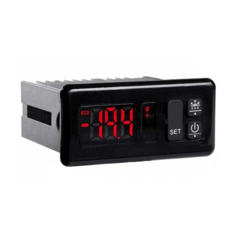
AKO AKO-10123 User manual

www.ako.com
1012H301 Ed.01
Reguladores de temperatura frontal largo en formato para hueco panel de 150 x 31 mm
Aparatos diseñados para visualizar, controlar y regular generadores de frío (desescarche manual o auto-
mático programable, ciclo continuo y control de alumbrado), con entrada para sondas del tipo NTC.
Índice
1 - Versiones y referencias 6 - Descripción de parámetros y mensajes
2 - Datos técnicos 7 - Transferencia de parámetros
3 - Instalación 8 - Mantenimiento
4 - Funciones del frontal 9 - Advertencias
5 - Ajuste y configuración
2- DATOS TÉCNICOS
Rango de temperatura: . . . . . . . . . . . . . . . . . . . . . . . . . . . . . . . . . . . . . . . . . . . . . . . -50 ºC a 99.9 ºC
Resolución, ajuste y diferencial: . . . . . . . . . . . . . . . . . . . . . . . . . . . . . . . . . . . . . . . . . . . . . . . . . 0,1 ºC
Entrada para sonda NTC: . . . . . . . . . . . . . . . . . . . . . . . . . . . . . . . . . . . . . . . . . . . . . . . . . . AKO-149XX
Precisión termométrica:. . . . . . . . . . . . . . . . . . . . . . . . . . . . . . . . . . . . . . . . . . . . . . . . . . . . . . . ± 1 ºC
Tolerancia de la sonda a 25 ºC:. . . . . . . . . . . . . . . . . . . . . . . . . . . . . . . . . . . . . . . . . . . . . . . . ± 0,4 ºC
Potencia máxima absorbida:. . . . . . . . . . . . . . . . . . . . . . . . . . . . . . . . . . . . . . . . . . . . . . . . . . . . . 7 VA
Temperatura ambiente de trabajo:. . . . . . . . . . . . . . . . . . . . . . . . . . . . . . . . . . . . . . . . . . . 5 ºC a 50 ºC
Temperatura ambiente de almacenaje:. . . . . . . . . . . . . . . . . . . . . . . . . . . . . . . . . . . . . . -30 ºC a 70 ºC
Clasificación dispositivo de control:
de montaje incorporado, de característica de funcionamiento automático acción Tipo 1.B, para utiliza-
ción en situación limpia, soporte lógico (software) clase A y funcionamiento continuo. Grado de conta-
minación 2 s/ UNE-EN 60730-1
Aislamiento doble entre alimentación, circuito secundario y salida relé.
Tensión asignada de impulso:. . . . . . . . . . . . . . . . . . . . . . . . . . . . . . . . . . . . . . . . . . . . . . . . . . 2500 V
Temperatura de ensayo de bola de presión:
Partes accesibles: . . . . . . . . . . . . . . . . . . . . . . . . . . . . . . . . . . . . . . . . . . . . . . . . . . . . . . . . . 75 ºC
Partes que posicionan elementos activos:. . . . . . . . . . . . . . . . . . . . . . . . . . . . . . . . . . . . . . . 125 ºC
Tensión y corriente declarados por los ensayos de EMC: . . . . . . . . . . . . . . . . . . . . . . . . . . 230 V 25 mA
3- INSTALACIÓN
El controlador debe ser instalado en un sitio protegido de las vibraciones, del agua y de los gases corro-
sivos, donde la temperatura ambiente no supere el valor reflejado en los datos técnicos.
Para que los controladores tengan un grado de protección IP65, deberá instalarse correctamente la junta
entre el aparato y el perímetro del hueco del panel donde deba montarse.
Para que la lectura sea correcta, la sonda debe ubicarse en un sitio sin influencias térmicas ajenas a
la temperatura que se desea medir o controlar.
3.1 Anclaje de equipos para montaje en panel:
El aparato debe montar-
se sobre un panel verti-
cal, en un hueco de 150
x 31 mm. La fijación
debe realizarse con 2
tornillos de Ø 2,9 mm. x
13 mm. de longitud
(suministrados con el
equipo).
E
3.2 Conexionado:
Véase esquema en la etiqueta de características de los aparatos.
La sonda y su cable NUNCA deben instalarse en una conducción junto con cables de potencia, control o
alimentación.
El circuito de alimentación debe estar provisto de un inte-
rruptor para su desconexión adecuado a las cargas instala-
das, situado cerca del aparato. El cable de alimentación será
del tipo H05VV-F 2 x 2.5 mm2o H05V-K 2 x 2.5 mm2.
Los cables para el conexionado del contacto del relé, deberán
tener una sección de 2.5 mm2.
HUECO PANEL
31
165
150
Ø2,5
1- VERSIONES Y REFERENCIAS
MODELO RELÉS ALIMENTACIÓN, 50/60 Hz
AKO-10123 1 x 16 A, 250 V, cos ϕ=1, SPST 230 V~ ±10%
1 x 8 A, 250 V, cos ϕ=1, SPDT
AKO-10223 1 x 16 A, 250 V, cos ϕ=1, SPST 230 V~ ±10%
2 x 8 A, 250 V, cos ϕ=1, SPDT
1 x 16 A, 250 V, cos ϕ=1, SPST
AKO-10323 2 x 8 A, 250 V, cos ϕ=1, SPDT 230 V~ ±10%
1 x 8 A, 250 V, cos ϕ=1, SPST
Indicadores:
LED Compresor
Fijo, indica que el compresor está activado.
Intermitente, que debería estar activado pero no
lo está por motivos de programación
(Temporización de seguridad actuando, deses-
carche en curso…).
LED Ventiladores
Fijo, indica que los ventiladores están activa-
dos. Intermitente, que deberían estar activados
pero no lo están por motivos de programación
(retardo, ventiladores parados durante el deses-
carche…).
LED Desescarche
Fijo, indica que el desescarche está activado.
LED Alarma
Fijo, indica que se ha producido una alarma .
Intermitente, pulsación de una tecla después de
la indicación de alarma.
LED PR
Intermitente, indica que el equipo está en fase
de programación.
LED DT
Intermitente, indica que el desescarche ha fina-
lizado por tiempo .
LED Ciclo Continuo
Fijo, indica que el ciclo continuo está activado.
LED Alumbrado
Fijo, indica que el alumbrado está encendido.
Teclas:
Tecla SUBIR / Ciclo Continuo Pulsando
durante 3 segundos, activa el CICLO CONTINUO
de la duración que se haya programado.
Pulsando durante 3 segundos con el CICLO CON-
TINUO activado, interrumpe el proceso de forma
inmediata.
En programación, sube el valor que se está
visualizando.
Tecla desescarche / Escape Pulsando du-
rante 3 segundos, activa un desescarche manual
de la duración que se haya programado.
Pulsando durante 3 segundos con el desescar-
che activado, interrumpe el proceso de forma
inmediata.
En programación, permite salir de un parámetro
sin aceptar los cambios, volver al menu anterior
y salir de programación.
Tecla ALUMBRADO Enciende / Apaga el relé
de alumbrado mediante su pulsación.
Tecla BAJAR En programación, baja el valor
que se está visualizando.
Tecla SET Pulsando durante 5 segundos
visualiza y permite programar la temperatura
del PUNTO DE AJUSTE (Set Point).
En programación, acepta el nuevo valor progra-
mado.
Tecla ON / OFF Pulsando durante 3 segun-
dos apaga el equipo dejándolo en STAND-BY. El
display muestra oFF cuando el equipo está des-
conectado. La tecla de ALUMBRADO sigue fun-
cionando aunque el equipo esté en modo oFF.
5- AJUSTE Y CONFIGURACIÓN
Sólo deben realizarse por personal que conozca el funcionamiento y las posibilidades del equipo donde
se aplica.
5.1 Ajuste de la temperatura
El valor de fábrica, de AJUSTE DE TEMPERATURA (Set Point) por defecto es de 0 ºC.
- Pulse la tecla durante 5 segundos para VISUALIZAR AJUSTE. Aparece el valor del AJUSTE ACTUAL
(Set Point) y se ilumina el LED “PR” de forma intermitente.
- Pulse las teclas o para VARIAR AJUSTE (Set Point) al valor deseado.
- Pulse la tecla para ACEPTAR EL NUEVO AJUSTE. La pantalla vuelve a INDICACION TEMPERATURA
y el LED “PR” deja de iluminar de forma intermitente.
En caso de aparecer PA, debe entrar el CÓDIGO ACCESO (Password) programado en el parámetro L5 para
acceder al AJUSTE ACTUAL (Set Point).
- Pulse la tecla . La pantalla muestra 0para ENTRAR CÓDIGO ACCESO.
- Pulse las teclas o para SELECCIONAR NÚMERO y MUESTRA CÓDIGO ACCESO (Password) pro-
gramado.
- Pulse la tecla para ACEPTAR CÓDIGO. Se visualiza el valor del AJUSTE ACTUAL (Set Point) que ya
puede ser modificado.
5.2 Configuración de parámetros
Nivel 1 Menús
- Pulse simultáneamente las teclas + durante 10 segundos. El LED “PR” se ilumina de forma
intermitente, se ha entrado en programación y en la pantalla aparece el primer menú “rE”.
- Pulse la tecla para acceder al menú siguiente y la tecla para retroceder al menú anterior.
- Pulsando la tecla el controlador vuelve a la situación de VISUALIZACION DE TEMPERATURA y el
LED “PR” deja de iluminar de forma intermitente.
En caso de aparecer PA, debe entrar el CÓDIGO ACCESO (Password) programado en el parámetro L5 del
menú tid para acceder a la programación.
- Pulse la tecla . La pantalla muestra 0para ENTRAR CÓDIGO ACCESO.
- Pulse las teclas o para SELECCIONAR NÚMERO y MUESTRA CÓDIGO ACCESO (Password) pro-
gramado.
- Pulse la tecla para ACEPTAR CÓDIGO. Se visualiza el primer menú “rE”.
Nivel 2 Parámetros
- Pulse la tecla en el menú de parámetros que desee acceder, aparecerá en el display el primer
parámetro del menú.
- Pulse la tecla para acceder al parámetro siguiente y la tecla para retroceder al parámetro
anterior.
- Pulsando la tecla el controlador vuelve al NIVEL 1 MENÚS.
Tecla
ON / OFF
LED Compresor
LED
Ventiladores
LED
Desescarche
LED Alarma
LED PR LED DT LED Ciclo Continuo
LED Alumbrado
Tecla SUBIR
Ciclo Continuo Tecla desescarche
Escape
Tecla
ALUMBRADO
Tecla BAJAR Tecla SET
4- FUNCIONES DEL FRONTAL
INDICACIÓN
TEMPERATURA
ACEPTAR
CÓDIGO
VISUALIZAR
AJUSTE
VARIAR
AJUSTE
ACEPTAR
EL NUEVO
ENTRAR
CÓDIGO
ACCESO
MUESTRA
CÓDIGO
ACCESO
AJUSTE
ACTUAL NUEVO
AJUSTE
Si P2=0 ó L5=0
PETICIÓN
CÓDIGO
ACCESO
SELECCIONAR
NÚMERO
5 Seg.
ACEPTAR
6
7 8 9 10 11 12 13 14 15
LIGHT COOL 230 V~ S1 - TEM
*16 A
*8 A
NNNL DI1
AKO-10123
12345
6
7 8 9 10 11 12 13 14 15 16 17 18
DEF FAN LIGHT COOL 230 V~ S1 - TEM S2 - DEF
*8 A *16 A
*8 A
NN NNNL DI1 DI2
*8 A
AKO-10323
1 2 3
6
7 8 9 10 11 12 13 14 15 16 17 18
R2 LIGHT COOL 230 V~ S1 - TEM S2 - DEF
*8 A *16 A
*8 A
NNNNL
DI1 DI2
AKO-10223
La corriente máxima permitida por el circuito de alimentación con todas las cargas conectadas es de 16A en todos los modelos.

Nivel 3 Valores
- Para VISUALIZAR el VALOR ACTUAL de cualquier parámetro, sitúese en el que se desea y pulse la tecla
. Una vez visualizado, si quiere VARIAR VALOR pulse las teclas o
- Pulse la tecla para ACEPTAR EL NUEVO VALOR o la tecla para CANCELAR LOS CAMBIOS. La
programación vuelve a NIVEL 2 PARÁMETROS.
NOTA: Si no se pulsa tecla alguna durante 25 segundos en cualquiera de los pasos anteriores, el con-
trolador volverá automáticamente a la situación de INDICACION TEMPERATURA, sin modificar el valor de
los parámetros.
6- DESCRIPCIÓN DE PARÁMETROS Y MENSAJES
Los valores de la columna Def. vienen programados de fábrica.
7- TRANSFERENCIA DE PARÁMETROS
Servidor portátil
Servidor portátil AKO-14918, sin alimentación, que se le
pueden copiar por transferencia, los parámetros progra-
mados en un controlador que esté alimentado. Los pará-
metros pueden transferirse de nuevo del servidor a otros
controladores idénticos que estén alimentados.
Para transferir parámetros, se dispone de otros servido-
res para controladores que deban ser programados todos
iguales en gran cantidad sin alimentación eléctrica.
Con conector para transferencia de parámetros.
9- ADVERTENCIAS
Utilizar el controlador no respetando las instrucciones del fabricante, puede alterar los requisitos de
seguridad del aparato.
Para el funcionamiento correcto del aparato solamente deberán utilizarse sondas del tipo NTC de las
suministradas por AKO.
Entre -40 ºC y +20 ºC, si se prolonga la sonda hasta 1.000 m con cable de mínimo 0,5 mm2, la desvia-
ción máxima será de 0,25 ºC (Cable para prolongación de sondas ref. AKO-15586)
La intensidad especificada para cada relé es su máxima individual, si se conectan más de uno, la
intensidad de la suma (COMPRESOR + DESESCARCHE + VENTILADOR + ALUMBRADO ) no debe reba-
sar la intensidad máxima total especificada en la etiqueta de características del equipo.
MENSAJES
PA Petición de código de acceso (Password) para entrar en programación de parámetros
o del PUNTO DE AJUSTE (Set Point)
Indica que se está efectuando un desescarche. Para que aparezcan las siglas "dEF"
dEF en la pantalla cuando se efectúa un desescarche, es indispensable que el parámetro d2
esté en opción 2.
AE Intermitente con temperatura - Alarma externa
AES Intermitente con temperatura - Alarma externa Severa
AH Intermitente con temperatura - La temperatura de la Sonda 1 excede el parámetro
programado en A1
AL Intermitente con temperatura - La temperatura de la Sonda 1 es inferior al parámetro
programado en A2
oFF Equipo apagado - Modo STANDBY (el equipo mantiene la alimentación eléctrica)
E1 Sonda 1 averiada (Circuito abierto, cruzado, temp.> 110ºC ó temp.<-55ºC)
E2 Sonda 2 averiada (Circuito abierto, cruzado, temp.> 110ºC ó temp.<-55ºC)
ES Configuración errónea de sonda (Véase P4, P8)
EE Fallo de memoria
Transferencia
Alimentación
Programación
AKO-14918
Nivel 1 Menús y Descripción
rE Nivel 2 Control REFRIGERACIÓN (Compresor)
Nivel 3 Descripción Valores Mín. Def. Máx.
C0 Calibración de la sonda 1 (Offset) (ºC/ºF) -20.0 0.0 20.0
C1 Diferencial de la sonda 1 (Histéresis) (ºC/ºF) 0.1 1.0 20.0
C2 Bloqueo superior del Punto de Ajuste (ºC/ºF) C3 99.9 99.9
(No se podrá fijar por encima de este valor)
C3 Bloqueo inferior del Punto de Ajuste (ºC/ºF) -50.0-50.0 C2
(No se podrá fijar por debajo de este valor)
C4 Tipo de retardo para protección del compresor: 001
0=OFF/ON (Desde última desconexión) 1=ON (A la conexión)
C5 Tiempo de retardo de la protección (min.) 0 0 255
(Valor de la opción elegida en parámetro C4)
C7
Tiempo del relé “COOL” (Compresor) en ON en caso de sonda 1 averiada
(min.) 0 10 255
(Si C7=0 y C8≠0, el relé estará siempre en OFF desconectado)
C8
Tiempo del relé “COOL” (Compresor) en OFF en caso de sonda 1 averiada
(min.) 0 5 255
(Si C8=0 y C7≠0, el relé estará siempre en ON conectado)
C9 Tiempo del relé “COOL” (Compresor) en ON durante ciclo continuo. (h.) 0 1 24
C10 ¿Paro de compresor al abrir puerta? (0=No) (1=Si) 0 0 1
dEF Nivel 2 Control DESESCARCHE
Nivel 3 Descripción Valores Mín. Def. Máx.
d0 Frecuencia de desescarche (Tiempo entre 2 inicios) (h.) 0 6 120
d1 Duración máxima del desescarche (min.) 0 30 255
Tipo de mensaje durante el desescarche:
d2 (0=Muestra la temperatura real) 022
(1=Muestra la temperatura de inicio de desescarche)
(2=Muestra el mensaje dEF)
d3
Duración máxima del mensaje (Tiempo añadido al final del desescarche)
(min.) 0 5 255
d4 Temperatura final de desescarche por sonda 2 (ºC/ºF)
-50.0 8.0 99.9
(Si está programado en P4) En modelos de 2 relés actúa si P6=0
d5 Desescarche al conectar el equipo: 001
(0=NO, primer desescarche según d0) (1=SÍ, primer desescarche según d6)
d6 Retardo de inicio del desescarche al conectar el equipo (min.) 0 0 255
d7 Tipo de desescarche: (0=Resistencias) (1=Inversión de ciclo) 001
Para desescarche por aire en 2 relés, es necesario programar P6 y F3
d8 Cómputo de tiempo entre períodos de desescarche: 001
(0=Tiempo real total) (1=Suma de tiempo del compresor conectado)
d9 Tiempo de goteo, paro de compresor (min.) 0 1 255
y relé FAN/R2 al finalizar un desescarche
FAn Nivel 2 Control VENTILADORES (Evaporador)
Nivel 3 Descripción Valores Mín. Def. Máx.
F0 Temperatura de paro de los ventiladores por sonda 2 (ºC/ºF) -50.0 4.0 99.9
(Si está programada en P4)
F1 Diferencial de la sonda 2 (ºC/ºF) 0.1 1.0 20.0
F2 ¿Parar ventiladores, al parar compresor?: (0=NO) (1=SÍ) 001
En modelos de 2 relés, R2 actúa si P6=1
F3 Estado de los ventiladores durante el desescarche: 001
(0=Parados) (1=En marcha)
F4 Retardo de arranque después del desescarche (min.) 0 3 255
(Actuará si es superior a d9)
F5 ¿Paro de ventiladores al abrir la puerta?: (0=NO) (1=SÍ) 0 0 1
AL Nivel 2 Control ALARMAS
Nivel 3 Descripción Valores Mín. Def. Máx.
A0 Configuración de las alarmas de temperatura 001
(0=Relativa al SP) (1=Absoluta)
A1 Alarma de máxima en sonda 1 (ºC/ºF) A2 0 99.9
A2 Alarma de mínima en sonda 1 (ºC/ºF)
-50.0 0 A1
A3 Retardo de alarmas de temperatura en la puesta en marcha (min.) 0 0 255
(Si se detectan programadas en A1, A2)
A4
Retardo de alarmas de temperatura desde que finaliza un desescarche
(min.) 0 0 255
8- MANTENIMIENTO
Limpie la superficie del controlador con un paño suave, agua y jabón. No utilice detergentes abrasivos,
gasolina, alcohol o disolventes.
NOTA: Cuando se modifican los parámetros de tiempo, los nuevos valores, los aplicará una vez finaliza-
do el ciclo que estaba realizando. Para que lo haga inmediatamente, desconectar y conectar de nuevo el
controlador.
Nos reservamos el derecho de suministrar materiales que
pudieran diferir levemente de los descritos en nuestras Hojas
Técnicas. Información actualizada en nuestra web: www.ako.com.
AKO ELECTROMECÀNICA, S.A.L.
351012301 REV.00 2005
D.L.: B-27040-06
Av. Roquetes, 30-38
08812 Sant Pere de Ribes (Barcelona)
e-mail: [email protected]
Tel. (34) 938 142 700 Fax (34) 938 934 054
Apartado (P.O. Box), 5
08800 Vilanova i la Geltrú (Spain)
SELECCIONAR
NÚMERO
VISUALIZAR
VALOR
PETICIÓN
CÓDIGO
ACCESO
ENTRAR
CÓDIGO
ACCESO
MUESTRA
CÓDIGO
ACCESO
VALOR
ACTUAL NUEVO
VALOR
SI L5=0
ACEPTAR
EL NUEVO
INDICACIÓN
TEMPERATURA NIVEL 2
PARÁMETROS NIVEL 3
VALORES
SALIDA
A NIVEL 1
ACEPTAR
CÓDIGO
CÓDIGO DE ACCESO (PASSWORD)
SI SE HA PROGRAMADO
VARIAR
VALOR
NIVEL 1
MENÚS
10 Seg.
SIMULTÁNEAMENTE
SALIDA
PROGRAMACIÓN
ACEPTAR
SALIDA
A NIVEL 2
ACEPTAR
A5 Retardo de alarmas de temperatura desde que deberían (min.) 0 30 255
activarse por temperatura
A6 Retardo de alarmas de temperatura (min.) 0 0 255
desde la desactivación de la entrada digital (Contacto puerta)
A7 Retardo de alarmas de temperatura (min.) 0 0 255
desde la activación de la entrada digital (Contacto puerta)
A8 Indicación si el desescarche finalizó por tiempo máximo: 001
(0=NO) (1= SÍ)
A10 Diferencial Alarmas Temperatura A1 y A2 (ºC/ºF) 0.1 1.0 20.0
inP Nivel 2 Entradas Digitales
Nivel 3 Descripción Valores Mín. Def. Máx.
Configuración de la entrada digital Nº1
i1C (0=Desactivada) (1=Contacto puerta) 005
(2=Alarma Externa) (3=Alarma Externa Severa)
(4=Desescarche remoto) (5=Cambio del punto de ajuste iS1 + it1)
i1d Retardo a las alarmas de la entrada digital Nº1 (min.) 0 0 255
i1P Polaridad de la entrada digital Nº1 0 0 1
Configuración de la entrada digital Nº2
i2C (0=Desactivada) (1=Contacto puerta) 005
(2=Alarma Externa) (3=Alarma Externa Severa)
(4=Desescarche remoto) (5=Cambio del punto de ajuste iS1 + it1)
i2d Retardo a las alarmas de la entrada digital Nº2 (min.) 0 0 255
i2P Polaridad de la entrada digital Nº2 0 0 1
iS1 Valor del punto de ajuste auxiliar 1 del Relé “COOL” (Compresor) (ºC/ºF) -50.0 0
+99.9
it1 Duración del punto de ajuste auxiliar 1 (min.) 0 0 255
CnF Nivel 2 ESTADO GENERAL
Nivel 3 Descripción Valores Mín. Def. Máx.
P1 Retardo de todas las funciones al recibir alimentación eléctrica (min.) 0 0 255
P2 Asignación de código de acceso (password) al Punto de Ajuste: 001
(0=Sin asignación) (1=Con asignación del código de acceso L5)
P3 Parámetros iniciales: (1=SÍ, configura en “Def” y sale de programación) 0 0 1
P4 Sondas conectadas: (1=Sonda 1) (2=Sonda 1 + Sonda 2) 1 1 2
P5 Dirección para equipos con comunicación 0 0 255
P6 Función del relé 2 (R2) en modelos de 2 relés: 001
(0=Desescarche) (1=Control de ventiladores)
Modalidad de visualización de la temperatura:
P7 (0=Enteros en ºC) (1=Un decimal en ºC) 0 1 3
(2=Enteros en ºF) (3=Un decimal en ºF)
P8 Sonda a visualizar: (1=Sonda 1) (2=Sonda 2) 1 1 2
tid Nivel 2 Control ACCESO E INFORMACIÓN
Nivel 3 Descripción Valores Mín. Def. Máx.
L5 Código de acceso (Password) a parámetros e información 0 0 255
L6 Transferir parámetros: (0=Desactivado) (1=Enviar) (2=Recibir) 0 0 2
PU Versión de programa (Información)

www.ako.com
1012H301 Ed.01
Large frontal temperature regulators, formatted for 150 x 31 mm panel cut-out
Devices designed to display, control and regulate cooling generators (manual or automatic programma-
ble defrosting, continuous cycle and lighting control) with input for NTC type probe.
Index
1 - Versions and references 6 - Parameters description and messages
2 - Technical data 7 - Parameters transfer
3 - Installation 8 - Maintenance
4 - Front panel functions 9 - Warnings
5 - Adjustment and configuration
2- TECHNICAL DATA
Temperature range: . . . . . . . . . . . . . . . . . . . . . . . . . . . . . . . . . . . . . . . . . . . . . . . . . . -50 ºC to 99.9 ºC
Resolution, Set Point and differential:. . . . . . . . . . . . . . . . . . . . . . . . . . . . . . . . . . . . . . . . . . . . . 0,1 ºC
Input for NTC probe:. . . . . . . . . . . . . . . . . . . . . . . . . . . . . . . . . . . . . . . . . . . . . . . . . . . . . . AKO-149XX
Thermometric accuracy:. . . . . . . . . . . . . . . . . . . . . . . . . . . . . . . . . . . . . . . . . . . . . . . . . . . . . . . ± 1 ºC
Probe tolerance at 25 ºC: . . . . . . . . . . . . . . . . . . . . . . . . . . . . . . . . . . . . . . . . . . . . . . . . . . . . ± 0,4 ºC
Maximum input power: . . . . . . . . . . . . . . . . . . . . . . . . . . . . . . . . . . . . . . . . . . . . . . . . . . . . . . . . . 7 VA
Working ambient temperature: . . . . . . . . . . . . . . . . . . . . . . . . . . . . . . . . . . . . . . . . . . . . . 5 ºC to 50 ºC
Storage ambient temperature:. . . . . . . . . . . . . . . . . . . . . . . . . . . . . . . . . . . . . . . . . . . . -30 ºC to 70 ºC
Control device classification:
Integrated mounting, with characteristic of automatic operation Type 1.B action, to be used in a clean
situation, logical medium (software) class A and continuous operation. Degree of contamination 2 on
UNE-EN 60730-1
Double insulation between the power supply, the secondary circuit and the relay output.
Allocated pulse voltage: . . . . . . . . . . . . . . . . . . . . . . . . . . . . . . . . . . . . . . . . . . . . . . . . . . . . . . 2500 V
Pressure ball test temperature:
Accessible parts: . . . . . . . . . . . . . . . . . . . . . . . . . . . . . . . . . . . . . . . . . . . . . . . . . . . . . . . . . . 75 ºC
Parts that position active elements: . . . . . . . . . . . . . . . . . . . . . . . . . . . . . . . . . . . . . . . . . . . 125 ºC
Voltage and current declared by the EMC tests: . . . . . . . . . . . . . . . . . . . . . . . . . . . . . . . . 230 V 25 mA
3- INSTALLATION
The controller should be installed in a place protected from vibrations, water and corrosive gases, and
where ambient temperature does not surpass the value specified in the technical data.
In order for the controllers to have IP65 protection, the gasket should be properly installed between the
apparatus and the perimeter of the panel cut-out where it is to be fitted.
In order to give a correct reading, the probe should be installed in a place without heat influences other
than the temperature that is to be measured or controlled.
3.1 Fastening units for panel mounting:
The device must be
mounted on a vertical
panel, in a 150 x 31 mm
cut-out. Fixing must be
performed with two 2.9
mm x 13 mm. long
screws (supplied with
the unit).
GB
3.2 Connection:
See diagram in the unit rating plate.
The probe and its lead should NEVER be installed in ducting along with power, control or power supply
wiring.
The power supply circuit should be connected with a switch
adapted to the installed loads located close the unit. Power
supply cables should be H05VV-F 2 x 2,5 mm2or H05V-K 2 x
2,5 mm2.
Section of connecting wires for relays contacts should be of
2,5 mm2.
PANEL CUT-OUT
31
165
150
Ø2,5
1- VERSIONS AND REFERENCES
MODEL RELAYS POWER SUPPLY, 50/60 Hz
AKO-10123 1 x 16 A, 250 V, cos ϕ=1, SPST 230 V~ ±10%
1 x 8 A, 250 V, cos ϕ=1, SPDT
AKO-10223 1 x 16 A, 250 V, cos ϕ=1, SPST 230 V~ ±10%
2 x 8 A, 250 V, cos ϕ=1, SPDT
1 x 16 A, 250 V, cos ϕ=1, SPST
AKO-10323 2 x 8 A, 250 V, cos ϕ=1, SPDT 230 V~ ±10%
1 x 8 A, 250 V, cos ϕ=1, SPST
Indicators:
Compressor LED
Fixed: it means that the compressor is active.
Flashing, it means that it should be active, but
it is not due to programming reasons (Safety
timing in operation, defrost in process…).
Fans LED
Fixed: it indicates that the fans are active.
Flashing, it means that they should be active,
but are not due to programming reasons (delay,
fans stopped during defrosting…).
Defrost LED
Fixed: it means that defrost is active.
Alarm LED
Fixed: it means that an alarm has occurred.
Flashing: it indicates pressing of a push-button
after the alarm indication.
PR LED
Flashing: it indicates that the unit is in pro-
gramming phase.
DT LED
Flashing: it indicates that defrost has finished
due to time.
Continuous Cycle LED
Fixed: it indicates that the continuous cycle is
active.
Lighting LED
Fixed: it indicates that lighting is on.
Teclas:
UP Key / Continuous Cycle Pressing during
3 seconds, it activates the CONTINUOUS CYCLE
during the time for which it has been program-
med.
Pressing during 3 seconds with the CONTI-
NUOUS CYCLE active, it interrupts the process
immediately.
In programming, it increases the displayed
value.
Defrost key / Escape Pressing during 3
seconds, it activates manual defrost during the
time for which it has been programmed.
Pressing during 3 seconds with defrost activated,
it interrupts the process immediately.
In programming, it permits leaving a parameter
without accepting the changes, return to the pre-
vious menu and exit programming.
LIGHTING Key By pressing it, it turns on /
off the lighting relay.
DOWN Key In programming, it decreases
the value being viewed.
SET Key Pressing during 5 seconds it dis-
plays and permits programming the SET POINT
temperature value.
In programming, it accepts the programmed
new value.
ON / OFF Key Pressing during 3 seconds it
turns off the unit leaving it in STAND-BY. The
display shows OFF when the unit is disconnec-
ted. The LIGHTING key continues operating even
if the unit is on OFF mode.
5- ADJUSTMENT AND CONFIGURATION
It should only be programmed or modified by personnel who are fully conversant with the equipment ope-
ration and possibilities.
5.1 Set Point temperature
The factory SET POINT default value is 0 ºC.
- Press key for at least 5 seconds to DISPLAY SET POINT. It displays the CURRENT SET POINT value
and LED “PR” starts flashing.
- Press or keys to CHANGE SET POINT into the required value.
- Press key to ACCEPT THE NEW SET POINT. The display returns to the CURRENT TEMPERATURE dis-
play status and LED “PR” stops flashing.
When PA is displayed, PASSWORD programmed in L5 parameter should be entered to access the
CURRENT SET POINT.
- Press key. 0will be displayed to ENTER PASSWORD.
- Press or keys to CHANGE NUMBER and DISPLAY PASSWORD.
- Press key to ACCEPT PASSWORD. The CURRENT SET POINT value will be displayed and it can be
already modified.
5.2 Parameters configuration
Level 1 Menus
- Press simultaneously + keys during 10 seconds. LED “PR” lights up intermittently, pro-
gramming has started, and the first menu “rE” appears on the screen.
- Press key to continue to next menu and key to return to previous menu.
- Pressing the key the controller returns to TEMPERATURE DISPLAY and LED “PR” stops flashing.
If PA appears, you must enter the ACCESS CODE (Password) programmed in parameter L5 of the tid
menu for accessing programming.
- Press key. The screen shows 0for ENTER ACCESS CODE (password)
- Press keys or for SELECTING NUMBER AND SHOWING ACCESS CODE (Password) programmed.
- Press key to ACCEPT CODE. First “rE” menu is viewed.
Level 2 Parameters
- Press key in the parameter menu you wish to access, the first parameter of the menu will appe-
ar on the display.
- Press key to access the following parameter and key to return to previous parameter.
- Pressing the key the controller returns to LEVEL 1 MENÚS.
ON / OFF
Key
Compressor LED
Fans LED
Defrost LED
Alarm LED
PR LED DT LED Continuous Cycle LED
Lighting LED
UP Key
Continuous Cycle Defrost key
Escape
LIGHTING
Key
DOWN Key SET Key
4- FRONT PANEL FUNCTIONS
CURRENT
TEMPERATURE
ACCEPT
PASSWORD
DISPLAY
SET POINT
CHANGE
SET POINT
ACCEPT
THE NEW
ENTER
PASSWORD DISPLAY
PASSWORD CURRENT
SET POINT NEW
SET POINT
If P2=0 or L5=0
PASSWORD
REQUEST
CHANGE
NUMBER
5 Seg.
ACCEPT
6
7 8 9 10 11 12 13 14 15
LIGHT COOL 230 V~ S1 - TEM
*16 A
*8 A
NNNL DI1
AKO-10123
12345
6
7 8 9 10 11 12 13 14 15 16 17 18
DEF FAN LIGHT COOL 230 V~ S1 - TEM S2 - DEF
*8 A *16 A
*8 A
NN NNNL DI1 DI2
*8 A
AKO-10323
1 2 3
6
7 8 9 10 11 12 13 14 15 16 17 18
R2 LIGHT COOL 230 V~ S1 - TEM S2 - DEF
*8 A *16 A
*8 A
NNNNL
DI1 DI2
AKO-10223
Maximum power supply circuit current allowed for all the loads is 16A in all models.

Level 3 Values
- To DISPLAY the CURRENT VALUE of any parameter, select the required one and press key. Once it
is displayed, if you wish to CHANGE VALUE, press or keys.
- Press key to ACCEPT THE NEW VALUE or key to CANCELL THE CHANGES. Programming returns
to LEVEL 2 PARAMETERS.
REMARK: If no key is pressed for 25 seconds in either of the previous steps, the controller will automa-
tically return to the CURRENT TEMPERATURE display status without modifying any of the parameters
values.
6- DESCRIPTION OF PARAMETERS AND MESSAGES
Values in the Def. column are factory-set.
7- PARAMETERS TRANSFER
Portable server
AKO-14918 portable server, with no power supply, in
which parameters programmed in a powered controller
can be copied by transfer. Parameters can be transferred
again from the server to other identical powered contro-
llers
To transfer parameters, other servers are available for
controllers that should be programmed identically in high
quantity without power supply.
With a connector for parameter transfer.
9- WARNINGS
The use of the unit without observing the manufacturer's instructions may alter its safety qualification.
To ensure correct operation of the apparatus, only NTC type probes supplied by AKO should be used.
Between -40 ºC and +20 ºC, when the probe is extended up to 1.000 m with minimum 0,5 mm2cable,
deviation will be less than 0.25 ºC (Probe extension cable ref. AKO-15586)
The intensity specified for each relay is its maximum individual value; if more than one is connec-
ted, the intensity of the addition (COMPRESSOR + DEFROST + FAN + LIGHTING ) must not exceed the
total maximum intensity specified in the rating plate.
MESSAGES
PA Password request to enter programming parameters
or SET POINT
It indicates defrosting is being carried out. In order to display "dEF"
dEF during defrosting, it is essential that parameter d2
is set to option 2.
AE Flashing with temperature - External alarm
AES Flashing with temperature - Severe external alarm
AH Flashing with temperature - Sensor 1 temperature exceeds the parameter
programmed in A1
AL Flashing with temperature - The Sensor 1 temperature is lower than the parameter
programmed in A2
oFF Unit off - STANDBY Mode (equipment maintains electric power supply)
E1 Sensor 1 failure (Open circuit, crossed, temp.> 110ºC or temp.<-55ºC)
E2 Sensor 2 failure (Open circuit, crossed, temp.> 110ºC or temp.<-55ºC)
ES Incorrect sensor configuration (See P4, P8)
EE Memory failure
Transfer
Power supply
Programming
AKO-14918
Level 1 Menus and Description
rE Level 2 REFRIGERATION control (Compressor)
Level 3 Description Values Min. Def. Max.
C0 Sensor 1 calibration (Offset) (ºC/ºF) -20.0 0.0 20.0
C1 Sensor 1 differential (Hysteresis) (ºC/ºF) 0.1 1.0 20.0
C2 Set Point upper limit (ºC/ºF) C3 99.9 99.9
(It cannot be set above this value)
C3 Set Point lower limit (ºC/ºF) -50.0-50.0 C2
(It cannot be set below this value)
C4 Compressor protection delay type: 001
0=OFF/ON (From the last switch-off) 1=ON (At switch-on)
C5 Protection delay time (min.) 0 0 255
(Value for the option selected in parameter C4)
C7 “COOL” (Compressor) relay time in ON in case of faulty sensor 1 (min.) 0 10 255
(If C7=0 and C8≠0, the relay will always be OFF disconnected)
C8 “COOL” (Compressor) relay time in OFF in case of faulty sensor 1 (min.) 0 5 255
(If C8=0 and C7≠0, the relay will always be ON connected)
C9 “COOL” (Compressor) relay time in ON during continuous cycle (h.) 0 1 24
C10 Compressor stops when opening door? (0=NO) (1=YES) 0 0 1
dEF Level 2 DEFROST control
Level 3 Description Values Min. Def. Max.
d0 Defrost frequency (Elapsed time between 2 starts) (h.) 0 6 120
d1 Defrost maximum duration (min.) 0 30 255
Type of message during defrost:
d2 (0=Current temperature display) 022
(1=Defrost start temperature display)
(2=Display dEF message)
d3 Message maximum duration (Time added at the end of defrost) (min.) 0 5 255
d4 Defrost final temperature by sensor 2 (ºC/ºF)
-50.0 8.0 99.9
(If programmed in P4) In 2 relay versions, it operates if P6=0
d5 Defrost start-up on equipment switch-on: 001
(0=NO, first defrost according to d0) (1=YES, first defrost according to d6)
d6 Defrost start-up delay on equipment switch-on (min.) 0 0 255
d7 Defrost type: (0=Electric heat) (1=Hot gas by-pass) 001
To defrost by air in 2 relays, parameters P6 and F3 should be programmed
d8 Time calculation between defrost periods: 001
(0=Total real time) (1=Compressor operation sum)
d9 Drip time, compressor stop and FAN/R2 (min.) 0 1 255
relay off when defrost ends
FAn Level 2 FANS control (Evaporator)
Level 3 Description Values Min. Def. Max.
F0 Fans stop temperature by sensor 2 (ºC/ºF) -50.0 4.0 99.9
(If programmed in P4)
F1 Sensor 2 differential (ºC/ºF) 0.1 1.0 20.0
F2 Stop fans, when compressor stops?: (0=NO) (1=YES) 001
In 2 relays versions, R2 operates if P6=1
F3 Fans status during defrost: 001
(0=Off) (1=On)
F4 Start-up delay after defrost (min.) 0 3 255
(Operates if it is higher than d9)
F5 Stop fans if the door opens?: (0=NO) (1=YES) 0 0 1
AL Level 2 ALARM control
Level 3 Description Values Min. Def. Max.
A0 Configuration of temperature alarms 001
(0=Relative to SP) (1=Absolute)
A1 Maximum alarm in sensor 1 (ºC/ºF) A2 0 99.9
A2 Minimum alarm in sensor 1 (ºC/ºF)
-50.0 0 A1
A3 Temperature alarm delay in the start-up (min.) 0 0 255
(If programmed in A1, A2)
A4 Temperature alarm delay from the end of a defrost (min.) 0 0 255
8- MAINTENANCE
Clean the controller surface with a soft cloth, soap and water. Do not use abrasive detergents, petrol,
alcohol or solvents.
REMARK: When time parameters are modified, the new values are applied when the current cycle is com-
pleted. In order for it to have an immediate effect, switch the controller off and then on again.
Nos reservamos el derecho de suministrar materiales que
pudieran diferir levemente de los descritos en nuestras Hojas
Técnicas. Información actualizada en nuestra web: www.ako.com.
AKO ELECTROMECÀNICA, S.A.L.
351012301 REV.00 2005
D.L.: B-27040-06
Av. Roquetes, 30-38
08812 Sant Pere de Ribes (Barcelona)
e-mail: [email protected]
Tel. (34) 938 142 700 Fax (34) 938 934 054
Apartado (P.O. Box), 5
08800 Vilanova i la Geltrú (Spain)
CHANGE
NUMBER
DISPLAY
VALUE
PASSWORD
REQUEST ENTER
PASSWORD DISPLAY
PASSWORD
CURRENT
VALUE NEW
VALUE
IF L5=0
ACCEPT
THE NEW
CURRENT
TEMPERTATURE
LEVEL 2
PARAMETERS LEVEL 3
VALUES
EXIT TO
LEVEL 1
ACCEPT
PASSWORD
PASSWORD
IF PROGRAMMED
CHANGE
VALUE
LEVEL 1
MENUS
10 Sec.
SIMULTANEUSLY
EXIT
PROGRAMMING
ACCEPT
EXIT TO
LEVEL 2
ACCEPT
A5 Temperature alarm delay from the (min.) 0 30 255
moment at which they should operate due to temperature
A6 Temperature alarm delay from (min.) 0 0 255
digital input disabling (Door contact)
A7 Temperature alarm delay from (min.) 0 0 255
digital input enabling (Door contact)
A8 Signals if defrost ends due to maximum time: 001
(0=NO) (1=YES)
A10 Differential Alarm Temperature A1 and A2 (ºC/ºF) 0.1 1.0 20.0
inP Level 2 Digital inputs
Level 3 Description Values Min. Def. Max.
Digital Input Nº1 configuration
i1C (0=Disabled) (1=Door contact) 005
(2=External alarm) (3=Severe external alarm)
(4=Remote defrost) (5=Change of set point iS1 + it1)
i1d Alarm delay of digital Input N° 1 (min.) 0 0 255
i1P Polarity of digital input N° 1 0 0 1
Digital Input Nº2 configuration
i2C (0=Disabled) (1=Door contact) 005
(2=External alarm) (3=Severe external alarm)
(4=Remote defrost) (5=Change of set point iS1 + it1)
i2d Alarm delay of digital input Nº2 (min.) 0 0 255
i2P Polarity of digital input Nº 2 0 0 1
iS1 Value of auxiliary set point 1 of “COOL” Relay (Compressor) (ºC/ºF) -50.0 0
+99.9
it1 Duration of auxiliary set point 1 (min.) 0 0 255
CnF Level 2 GENERAL STATUS
Level 3 Description Values Min. Def. Max.
P1 Delay of all functions on power supply switch on (min.) 0 0 255
P2 Allocation of password to Set Point: 001
(0=Without allocation) (1=With allocation of L5 password)
P3 Initial parameters: (1=YES, configure to “Def” and exit programming) 0 0 1
P4 Connected sensors: (1=Sensor 1) (2=Sensor 1 + Sensor 2) 1 1 2
P5 Address for units with communication 0 0 255
P6 Relay 2 (R2) function in 2 relay versions: 001
(0=Defrost) (1=Fans control)
Temperature display mode:
P7 (0=Integers in ºC) (1=One decimal in ºC) 0 1 3
(2=Integers in ºF) (3=One decimal in ºF)
P8 Sensor to be displayed: (1=Sensor 1) (2=Sensor 2) 1 1 2
tid Level 2 ACCESS AND INFORMATION control
Level 3 Description Values Min. Def. Max.
L5 Access password to parameters and information 0 0 255
L6 Parameters transfer: (0=Disabled) (1=Send) (2=Receive) 0 0 2
PU Program version (Information)
This manual suits for next models
2
Table of contents
Languages:
Other AKO Controllers manuals