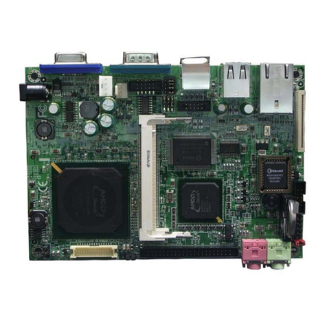
Data Modul eDM-CB-SM-IPCS User manual

eDM-CB-SM-IPCS
REFFERENCE MANUAL
www.data-modul.com

2 12048231 Rev. 00 (Draft)
DATA MODUL AG | www.data-modul.com
Document Revision History
Revision
Revision History
Date
00
Draft version
12.12.2021
Reference to this Operating Manual
The purpose of all the figures and illustrations in this User Manual is merely to provide a better explanation and
can differ to the actual appearance of the devices. They are to be understood as schematic representations.
© 2021 DATA MODUL AG. All rights reserved.
Trademarks:
Although all the information contained within this document is carefully checked, no guarantee of correctness is
implied or expressed. All brand or product names are trademarks or registered trademarks of their respective
owners.
Technical and optical changes as well as misprints reserved.

12048321 Rev. 01 (Draft) 3
DATA MODUL AG | www.data-modul.com
Contents
Contents.................................................................................................................................................................................. 3
1. Preface....................................................................................................................................................................... 6
1.1. Using this Document.............................................................................................................................................. 6
1.2. Purpose of this Document...................................................................................................................................... 6
1.3. Danger Symbols & Levels...................................................................................................................................... 6
Danger Symbols............................................................................................................................................................... 6
Danger Levels.................................................................................................................................................................. 6
General Symbols.............................................................................................................................................................. 6
1.4. Technical Support.................................................................................................................................................. 7
1.5. List of Abbreviations............................................................................................................................................... 7
1.6. General Connector Signal Description................................................................................................................... 8
1.7. Industry Specifications........................................................................................................................................... 8
2. Standards & Certifications.......................................................................................................................................... 8
2.1. SMARC Standard .................................................................................................................................................. 8
2.2. Material Compliance.............................................................................................................................................. 8
2.3. EMC Standards...................................................................................................................................................... 8
2.4. Safety..................................................................................................................................................................... 8
2.5. Shock & Vibration .................................................................................................................................................. 8
2.6. Environmental Conditions...................................................................................................................................... 8
2.7. Functional Block Diagram...................................................................................................................................... 9
2.8. Ordering Information............................................................................................................................................ 10
2.9. Connector Positions............................................................................................................................................. 10
2.10. Connector List...................................................................................................................................................... 11
2.11. Power Supply....................................................................................................................................................... 12
Input Voltage.................................................................................................................................................................. 12
3. External Connectors (IO-Shield)............................................................................................................................... 13
3.1. Gigabit Ethernet 0/1............................................................................................................................................. 13
3.2. Micro-SD Socket.................................................................................................................................................. 14
3.3. Line-Out Audio Connector.................................................................................................................................... 15
3.4. USB 2.0 Dual Type-A Connector......................................................................................................................... 16
3.5. DisplayPort Connector......................................................................................................................................... 17
3.6. USB 3.0 Dual Type-A Connector......................................................................................................................... 17
3.7. USB Single Type-C Connector ............................................................................................................................ 18
4. Internal Connectors.................................................................................................................................................. 19
4.1. SMARC Connector .............................................................................................................................................. 19
4.2. Power IN Supply Voltage Connector.................................................................................................................... 29
4.3. M.2 Key A Connector........................................................................................................................................... 30
4.4. M.2 Key B Connector........................................................................................................................................... 31

4 12048231 Rev. 00 (Draft)
DATA MODUL AG | www.data-modul.com
4.5. Nano-SIM Connector........................................................................................................................................... 31
4.6. M.2 Key M Connector.......................................................................................................................................... 32
4.7. SATA 7-Pin Connector......................................................................................................................................... 33
4.8. USB 2.0 Port 1D on Molex PicoBlade.................................................................................................................. 34
4.9. USB 2.0 Port 1B/C on 9-pin Pin-header............................................................................................................... 35
4.10. USB 3.0 19-pin Pin-header.................................................................................................................................. 36
4.11. SPI0 Socket / Pin-header..................................................................................................................................... 37
4.12. SPI0 Socket / Pin-header..................................................................................................................................... 38
4.13. UART SER0 Connector....................................................................................................................................... 39
4.14. UART SER1 Connector....................................................................................................................................... 40
4.15. RS485 (SER2) Connector.................................................................................................................................... 41
4.16. RS232 (SER3) Connector.................................................................................................................................... 42
4.17. I2S Audio Microphone.......................................................................................................................................... 43
4.18. Audio Frontpanel Pin-header............................................................................................................................... 44
4.19. CAN0 Connector.................................................................................................................................................. 45
4.20. LVDS Display Connector..................................................................................................................................... 46
4.21. V-By-One Display Connector............................................................................................................................... 48
4.22. V-By-One Display-Power-Connector (TCON)...................................................................................................... 51
4.23. LVDS Display Backlight Connector...................................................................................................................... 52
4.24. V-By-One Display Backlight Connector ............................................................................................................... 53
4.25. System-Fan Connectors ...................................................................................................................................... 54
4.26. DOOR Contact Connector ................................................................................................................................... 55
4.27. Infrared-IF Connector........................................................................................................................................... 56
4.28. GBE0,1 Precision Time Protocol Extension Connector ....................................................................................... 57
4.29. Data Modul Feature Connector............................................................................................................................ 58
4.30. Piezo-Speaker (Buzzer)....................................................................................................................................... 60
4.31. RTC-Battery Internal Connector........................................................................................................................... 61
4.32. RTC-Battery CR2023 Socket............................................................................................................................... 61
4.33. System-I2C Connectors....................................................................................................................................... 62
4.34. System-I2C 5V Connectors.................................................................................................................................. 63
4.35. External Power-Button Connector........................................................................................................................ 63
5. Jumpers, Switches and Status LEDs ....................................................................................................................... 64
5.1. Boot-Select Jumper ............................................................................................................................................. 64
5.2. V-TCON Selection Jumper................................................................................................................................... 65
5.3. Power-Button....................................................................................................................................................... 66
5.4. Reset-Button........................................................................................................................................................ 66
5.5. System-State Status LEDs................................................................................................................................... 67
5.6. M.2 and SATA-Activity LEDs ............................................................................................................................... 67
5.7. USB Type-C Status LEDs.................................................................................................................................... 67

12048321 Rev. 01 (Draft) 5
DATA MODUL AG | www.data-modul.com
5.8. USB Type-C Multiplexing Scheme....................................................................................................................... 68
6. Functional Exclusives and Shared Resources ......................................................................................................... 69
6.1. DisplayPort (DP1) Sharing................................................................................................................................... 69
6.2. USB3.0 (Port 2) Sharing ...................................................................................................................................... 70
6.3. USB2.0 (Port 1B) Sharing.................................................................................................................................... 71
6.4. Audio (Line Out) J37 Shared Sources ................................................................................................................. 71
6.5. Audio (Internal Pin-header) J36 Shared Sources................................................................................................. 72
6.6. I2S0 Interface Sharing......................................................................................................................................... 73
6.7. SATA Interface Sharing ....................................................................................................................................... 73
6.8. Power Supply to V-By-One Display (V-TCON) .................................................................................................... 74
6.9. I2C Devices.......................................................................................................................................................... 74
6.10. I2C Bus Topology ................................................................................................................................................ 75
7. Mechanical Design and EMI/ESD Shielding............................................................................................................. 76
7.1. PCB Size.............................................................................................................................................................. 76
7.2. Maximum component height................................................................................................................................ 76
7.3. Mounting Holes.................................................................................................................................................... 76
7.4. Mounting Concept................................................................................................................................................ 77
7.5. EMI and ESD-Shielding ....................................................................................................................................... 77
7.6. Mounting Holes - Mechanical Positions ............................................................................................................... 78
All dimensions given are in millimeters [mm].................................................................................................................. 78

6 12048231 Rev. 00 (Draft)
DATA MODUL AG | www.data-modul.com
1. Preface
1.1.Using this Document
In this Document, the eDM-CB-SM-IPCS is also referred to as „CB“.
Please read this Document before using this Carrier Board (CB).
This Document contains information about the hardware, software and configuration of the eDM-CB-SM-IPCS.
Awareness of the safety instructions and instructions for use in this Document will ensure the safe and correct use of the
eDM-CB-SM-IPCS.
In addition to the information given here, you should comply with the local regulations for the prevention of accidents and
generally applicable safety regulations.
1.2.Purpose of this Document
The purpose of this document is the definition of the technical parameters, the electrical connections and the mechanical
dimensions of the eDM-CB-SM-IPCS.
1.3.Danger Symbols & Levels
In this Document, symbols are used to highlight important safety instructions and any advice relating to the board. The
instructions should be followed very carefully to avoid any risk of accident, personal injury or property damage.
Danger Symbols
Dangerous Voltage, danger of electric shock
Hazard point
All DATA MODUL AG products are electrostatic sensitive
devices and are packaged accordingly. Do not open or handle
a DATA MODUL AG product except at an electrostatic-free
workstation. Additionally, do not ship or store DATA MODUL
AG products near strong electrostatic, electromagnetic,
magnetic, or radioactive fields unless the device is contained
within its original manufacturer's packaging. Be aware that
failure to comply with these guidelines will void the DATA
MODUL AG Limited Warranty.
Danger Levels
DANGER
Indicates a hazardous situation, which will result in death or
serious injury.
WARNING
Indicates a hazardous situation, which could result in death or
serious injury.
CAUTION
Indicates a hazardous situation, which may result in minor or
moderate injury.
NOTICE
Indicates a property damage.
General Symbols
Additional support or useful information.
The crossed-out refuse bin indicates that the products have to
be properly recycled or disposed of in accordance with national
legislation in the respective EU countries.
If you wish to dispose of usedelectrical and electronic products
outside the European Union, please contact your local
authority so as to comply with the local regulations.

12048321 Rev. 01 (Draft) 7
DATA MODUL AG | www.data-modul.com
1.4.Technical Support
DATA MODUL's technicians and engineers are committed to provide the best possible technical support for our customers
to enable an easy use and implementation of our products. We recommend to visit our website at www.data-modul.com first
for the latest documentation, utilities and drivers, which have been made available to assist you. If you need further assistance
after visiting our website please contact our technical support department by email at [email protected].
1.5.List of Abbreviations
Abbreviation
Description
BOM
CB
CMOS
CSI
DFP
DMIS
DP
DSI
EMI
EN
FFC
FHD
GBE
GND
GPIO
HDA
HDMI
I2C
I2S-Audio
JTAG
LCD
LVDS
NA
NC
PCB
PCIe
PMC
PWM
RefDes
RTC
SATA
SMBus
SPI
TBD
TMDS
TTL
UART
USB
Vx1
Bill of Materials
Carrier Board
Complementary MOS
MIPI-Camera Serial Interface
Downstream Facing Port (USB Type-C)
Data Modul Inhouse Stanard
DisplayPort or Differential Pair in relation to Pin Type
MIPI-Display Serial Interface
Electro Magnetic Interference
European Norm
Flat Foil Cable
Full-HD Graphics Resolution
Gigabit Ethernet
Ground
General purpose Input/Output
High Definition Audio Interface
High Definition Multimedia Interface
Inter-Integrated Circuit Bus
I2S Audio Interface
Joint Test Action Group
Liquid Crystal Display
Low-Voltage Differential Signaling
Not Available
Not Connected
Printed Circuit Board
PCI Express
Management Controller
Pulse Width Modulation
Reference Designator
Real Time Clock
Serial ATA
System Management Bus
Serial Peripheral Interface
To Be Defined
Transition-Minimized Differential Signaling.
Transistor-Transistor Logic
Universal Asynchronous Receiver/Transmitter
Universal Serial Bus
V-By-One Display Interface

8 12048231 Rev. 00 (Draft)
DATA MODUL AG | www.data-modul.com
1.6.General Connector Signal Description
Type
Description
IO
Bi-directional
I
Input
O
Output
GND
Ground connection
Power
Power connection
NC
Not connected
Analog
Analog signal
DP
Differential pair
1.7.Industry Specifications
Specification
Link
SMARC Hardware Specification 2.1.1
Extended Display Identification Data Standard EDID™
Enhanced Display Data Channel Specification DDC
Universal Serial Bus (USB) Specification
Serial ATA Specification
High Definition Audio Specification
IEEE standard 802.3ab 1000BASE-T Ethernet
http://sget.org
http://www.vesa.org
http://www.vesa.org
http://www.usb.org/home
http://www.serialata.org
http://www.intel.com
http://www.ieee.org
2. Standards & Certifications
2.1.SMARC Standard
eDM-CB-SM-IPCS is compliant to SMARC 2.0 and SMARC 2.1.1 specification.
2.2.Material Compliance
The PCB is produced under lead free soldering conditions.
All components are produced according to European RoHS (RoHS-1 = 2002/95/EU, RoHS-2 = 2011/65/EU) and REACH
(2006/1907/EU) regulations.
2.3.EMC Standards
Design to meet EN 55032-B within enclosure
EN61000-4-2 contact discharge 4kV
EN61000-4-2 air discharge 8kV
2.4.Safety
Designed to meet EN60950, EN62638 and UL60950.
2.5.Shock & Vibration
Designed to meet IEC/EN60068 and IEC/EN60068-2-27
2.6.Environmental Conditions
The eDM-CB-SM-IPCS is able to be operated and stored under the following environmental conditions:
Temperature (operating): 0°C … +60°C (commercial grade)
Temperature (storage): -15°C … +60°C
Relative humidity: < 90%

12048321 Rev. 01 (Draft) 9
DATA MODUL AG | www.data-modul.com
2.7.Functional Block Diagram
Figure 1 Functional Block Diagram

10 12048231 Rev. 00 (Draft)
DATA MODUL AG | www.data-modul.com
2.8.Ordering Information
Model Name
Part No.
Description
eDM-CB-SM-IPCS
12048231
SMARC 2.1.1 Carrier Board with full sampled parts according to the Data
Modul HW Specification for this product.
2.9.Connector Positions
Figure 2 Connector Positions

12048321 Rev. 01 (Draft) 11
DATA MODUL AG | www.data-modul.com
2.10. Connector List
Reference
Designator
Interface / Function
J1
SMARC module connector
J2
Power In Connector (24V)
J3
Data Modul IR-keyboard interface connector
J4
I2C_SW interface connector from STM32 board controller (CMOS-5V)
J5
I2C_SW interface connector from STM32 board controller (CMOS-5V)
J6
I2C_SW interface connector from STM32 board controller (CMOS-3.3V)
J7
I2C_SW interface connector from STM32 board controller (CMOS-3.3V)
J8
Door contact connector
J9
System FAN1 connector
J10
System FAN2 connector
J11
System FAN3 connector
J12
System FAN4 connector
J16
M.2 Key-A connector
J17
SIM-Card socket (only in combination with J18)
J18
M.2 Key-B connector
J19
M.2 Key-M connector
J20
SATA L-Shape connector
J21
USB2.0 (9-pin) internal pin-header
J22
USB2.0 dual Type-A connector on IO-shield
J23
USB 2.0 Port (1D) Molex-PicoBlade internal connector
J24
USB3.0 Dual Type-A connector on IO-shield
J25
USB3.0 (19-pin) internal pin-header
J26
USB single Type-C
J27
USB Type-C SPI-programming connector (internal use only)
J28
DisplayPort connector on IO-shield (DDI0 from SMARC)
J29
Backlight connector for LVDS display
J30
LVDS Display connector
J31
V-By-One Debug Connector (internal use only)
J32
V-By-One Display connector
J33
Backlight connector for V-By-One display
J34
Gigabit ethernet-0 connector
J35
Gigabit ethernet-1 connector
J36
Audio frontpanel pin-header
J37
Audio line-out connector
J39
I2S audio microphone connector

12 12048231 Rev. 00 (Draft)
DATA MODUL AG | www.data-modul.com
J40
Micro-SD card socket
J41
CAN-bus connector
J42
SPI0 pin-header
J43
SPI1 pin-header
J44
Boot-select jumpers
J47
UART 1.8V connector (SER0)
J48
UART 1.8V connector (SER1)
J49
RS232 connector (SER3)
J50
RS485 connector (SER2)
J51
Data Modul feature connector (Rev.100)
J52
FW-update/debug for STM32-board controller (internal use only)
J54
RTC-battery internal connector
J55
RTC battery CR2032 socket
J56
Optional TCON voltage connector for V-By-One display
J58
GbE0/1 PTP (Precision Time Protocol) extension
J60
V-By-One TCON voltage selection jumper
J61
Power button internal connector
SW1
Power button
SW2
Reset button
2.11. Power Supply
Input Voltage
VCC: 24.0 V ± 5%
Voltage Ripple: max. 100mV peak to peak 0 … 20 MHz
Rise Time: 0.1 … 20ms from input voltage < 10% nominal VCC
Max. inrush current VCC: 5A
Max. supply current 12A.
The maximum supply current must be limited to 12A by the power supply unit!

12048321 Rev. 01 (Draft) 13
DATA MODUL AG | www.data-modul.com
3. External Connectors (IO-Shield)
3.1.Gigabit Ethernet 0/1
Reference designator: –J34(GBR0) / J35(GBE1)
Description
The eDM-CB-SM-IPCS provides two gigabit ethernet ports of the SMARC module GBE0 on J34 and GBE1 on J35.
Each of RJ-45 connectors has integrated magnetics and two LEDs for link activity and mode indication.
Interfaces used
Media depended interface (MDI) 0 of the SMARC module on J34
Media depended interface (MDI) 1 of the SMARC module on J35
Connector drawing and contact-numbering scheme
Figure 3 Connector –J34/J35
LED Indication
Mode
LED 1
LED 2
Link
yellow
1000Mbit
orange
yellow blinking
100Mb
green
yellow blinking
10Mb
off
yellow blinking

14 12048231 Rev. 00 (Draft)
DATA MODUL AG | www.data-modul.com
3.2.Micro-SD Socket
Reference designator: J40
Micro-SD connector; ultra-low-profile; push-push type
Description
The micro-SD ultra-low-profile, push-push type socket provides 4-bit SDIO interface of the SMARC module. The
SDIO performance is depended on used SMARC module platform.
Interfaces used
SDIO interface of the SMARC module
Connector drawing and contact-numbering scheme
Figure 4 Micro-SD Socket –J40
Pinout
J40
Pin
Signal / Function
Pin Type
Signal Description
1
SDIO_DATA2
IO (1.8/3.3V)
Serial data line 2
2
SDIO_DATA3
IO (1.8/3.3V)
Serial data line 3
3
SDIO_CMD
IO (1.8/3.3V)
Command Line
4
VCC
Power(3.3V)
3.3V power-supply for connected device; max. current
100mA
5
SDIO_CLK
O (1.8/3.3V)
Data clock
6
GND
GND
Device power ground
7
SDIO_DATA0
IO (1.8/3.3V)
Serial data line 0
8
SDIO_DATA1
IO (1.8/3.3V)
Serial data line 1

12048321 Rev. 01 (Draft) 15
DATA MODUL AG | www.data-modul.com
3.3.Line-Out Audio Connector
Reference Designator: –J37
Green 3,5mm stereo-audio jack with presence detect support.
Description
This connector provides audio line-out optional either of the HD-Audio codec (ALC888S) or I2S codec (WM8904).
See more details about shard resources in chapter “Functional Exclusives and Shared Resources”.
Interfaces used
Line-out signals of the HDA or I2S audio codec
Connector drawing and contact-numbering scheme
Figure 5 Connector –J37
Pinout
J37
Pin
Signal / Function
Pin Type
Signal Description
1
GND
GND
Connected to ground potential of the PCB
2
Line-Out left
O (Analog)
Audio line out (left channel)
3
Line-Out right
O (Analog)
Audio line out (right channel)
4
Presence detect in
I (Analog)
This input is connected to HDA codec resistor network
5
GND
GND
Connected to ground potential of the PCB

16 12048231 Rev. 00 (Draft)
DATA MODUL AG | www.data-modul.com
3.4.USB 2.0 Dual Type-A Connector
Reference Designator: –J22
Description
Standard USB 2.0 Dual Type-A connector with supported cable length of max. 1,5 m.
Shared Port: USB Port 1B (upper port) is shared with the internal USB pin-header J21. Availability of one or the
other interface dependent on exact product variant based on this electronic design.
For manual modifications of the Port routing, see Chapter “Functional Exclusives and Shared Resources”.
Interfaces used
USB 2.0 port 1B (upper connector port) of the USB hub)
USB 2.0 port 1A (upper connector port) of the USB hub)
Supplied by 5.0 V S5 voltage
Current limited to 500 mA for each port.
Connector drawing and contact-numbering scheme
Figure 6 Connector –J22
Pinout
According to USB 2.0 Specification

12048321 Rev. 01 (Draft) 17
DATA MODUL AG | www.data-modul.com
3.5.DisplayPort Connector
Reference Designator: –J28
Description
One standard DisplayPort connector is provided on the front of the eDM-CB-SM-IPCS.
Interface used
DisplayPort DP0 from the SMARC module. The graphic performance is depended on used SMARC module.
Connector drawing and contact-numbering scheme
Figure 7 Connector –J28
3.6.USB 3.0 Dual Type-A Connector
Reference Designator: –J24
Description
Standard USB 3.0 Dual Type-A connector with supported cable length of max. 1,5 m.
Shared Port: USB 2.0 and 3.0 Port 2 (upper port) is shared with the USB Type-C connector J26.
Availability of one or the other interface dependent on exact product variant based on this electronic design.
For manual modifications of the Port routing, see Chapter “Functional Exclusives and Shared Resources”.
Interfaces used
USB 3.0 port 2 (shared port) and 3 for the SMARC module
USB 2.0 port 2 (shared port) and 3 of the SMARC module
Supplied by 5.0 V S5 voltage
Current limited to 900 mA for each port.
Connector drawing and contact-numbering scheme
Figure 8 Connector –J24

18 12048231 Rev. 00 (Draft)
DATA MODUL AG | www.data-modul.com
3.7.USB Single Type-C Connector
Reference Designator: –J26
Description
The Carrier Board provides one single USB Type-C connector right-angled SMT/THT combined mounting.
Features supported
DisplayPort DP1 from the SMARC module (shared with V-By-One Transmitter)
USB 2.0 Port 2 from the SMARC module (shared with upper port of dual Type-A connector J24)
USB 3.2 (5.0 Gbit/s) Port 2 from the SMARC module (shared with upper port of dual Type-A connector J24)
See more details about shard resources in chapter “Functional Exclusives and Shared Resources”.
Power delivery PD3 (USB_PD_R3_0)
5,0V max. current: 3,0 A
9,0V max. current: 3,0 A
15,0V max. current: 3,0 A
20,0V max. current: 5,0 A
Connector drawing and contact-numbering scheme
Figure 9 Connector –J26

12048321 Rev. 01 (Draft) 19
DATA MODUL AG | www.data-modul.com
4. Internal Connectors
4.1.SMARC Connector
Reference Designator: J1
Description
Socket and mechanical space including mounting holes and standoffs to support SMARC 2.0 / 2.1 modules
according to the standards specification Rev. 2.1.1
Interfaces provided (excluding unused interfaces)
PCI Express Ports A,B,C
USB 2.0 Ports 0,1,4,5
USB 3.0 Ports 2,3
GBE 0, 1
SATA
LVDS 0,1
DisplayPort 0
DisplayPort 1
SDIO
SPI0
eSPI as SPI1 (SPI Mode)
I2S0, HDA
SER 0, 1, 2, 3
CAN 0
I2C_GP
I2C_PM
12 GPIOs
Power- and System-Status signalling
Figure 10 SMARC Connector –J1
Pinout (for more details about pinout , see to SMARC Specification 2.1.1)
Note: the input/output pin type/direction is described from the carrier board view.
Pin
Signal / Function
Pin Type
Signal Description
Device/Connection
P1
SMB_ALERT#
O (OD 1.8V-
5V)
SMBus Alert# (Interrupt) signal
J44 Feature
Connector and
Board Controller
STM32
P2
GND
GND
Connected to ground potential of the PCB
GND
P3
CSI1_CK+
O DP D-PHY
CSI1 differential clock input (point to point)
not connected on
CB
P4
CSI1_CK-
P5
GBE1_SDP
IO (CMOS
3.3V)
IEEE 1588 trigger signals (GBE[0]_SDP)
J58 (PicoBlade)
P6
GBE0_SDP
IO (CMOS
3.3V)
IEEE 1588 trigger signals (GBE[0]_SDP)
J58 (PicoBlade)

20 12048231 Rev. 00 (Draft)
DATA MODUL AG | www.data-modul.com
Pin
Signal / Function
Pin Type
Signal Description
Device/Connection
P7
CSI1_RX0+
O DP D/M-PHY
CSI1 differential input (point to point)
not connected on
CB
P8
CSI1_RX0-
P9
GND
GND
Connected to ground potential of the PCB
GND
P10
CSI1_RX1+
O DP D/M-PHY
CSI1 differential input (point to point)
not connected on
CB
P11
CSI1_RX1-
P12
GND
GND
Connected to ground potential of the PCB
GND
P13
CSI1_RX2+
O DP D/M-PHY
CSI1 differential input (point to point)
not connected on
CB
P14
CSI1_RX2-
P15
GND
GND
Connected to ground potential of the PCB
GND
P16
CSI1_RX3+
O DP D/M-PHY
CSI1 differential input (point to point)
not connected on
CB
P17
CSI1_RX3-
P18
GND
GND
Connected to ground potential of the PCB
GND
P19
GBE0_MDI3-
IO (GBE MDI)
Differential pair signals for external transformer
J34 (RJ45)
P20
GBE0_MDI3+
P21
GBE0_LINK100#
I OD (CMOS
3.3V)
Link speed indication LED for GBE0 100Mbps
J34 (RJ45)
P22
GBE0_LINK1000#
I OD (CMOS
3.3V)
Link speed indication LED for GBE0 1000Mbps
J34 (RJ45)
P23
GBE0_MDI2-
IO (GBE MDI)
Differential pair signals for external transformer
J34 (RJ45)
P24
GBE0_MDI2+
P25
GBE0_LINK_ACT#
I OD (CMOS
3.3V)
Link / activity indication for GBE0
J34 (RJ45)
P26
GBE0_MDI1-
IO (GBE MDI)
Differential pair signals for external transformer
J34 (RJ45)
P27
GBE0_MDI1+
P28
GBE0_CTREF
Analog (0 to
3.3V)
Center-Tap ref. voltage for GBE0 magnetic
J34 (RJ45)
P29
GBE0_MDI0-
IO (GBE MDI)
Differential pair signals for external transformer
J34 (RJ45)
P30
GBE0_MDI0+
P31
SPI0_CS1#
I (CMOS 1.8V)
SPI chip select 0 (SPI boot)
not connected on
CB
P32
GND
GND
Connected to ground potential of the PCB
GND
P33
SDIO_WP
O OD (CMOS
1.8V/3.3V)
SDIO write protect
Tied to GND
P34
SDIO_CMD
IO (CMOS
1.8V/3.3V)
SDIO command/response
J40 (10R serial
resistor)
P35
SDIO_CD#
IO (OD
1.8V/3.3V)
SDIO card detection
J40
P36
SDIO_CK
I (CMOS
1.8/3.3V)
SDIO clock
J40
P37
SDIO_PWR_EN
I (CMOS 3.3V)
SDIO power enable
Power Switch of
Micro-SD Card
P38
GND
GND
Connected to ground potential of the PCB
GND
P39
SDIO_D0
IO (CMOS
1.8V/3.3V)
SDIO data lines. These signals operate in push-
pull mode.
J40 (10R serial
resistors)
P40
SDIO_D1
P41
SDIO_D2
P42
SDIO_D3
Table of contents
Other Data Modul Computer Hardware manuals
Popular Computer Hardware manuals by other brands

ST
ST STM32MP157D-DK1 user manual
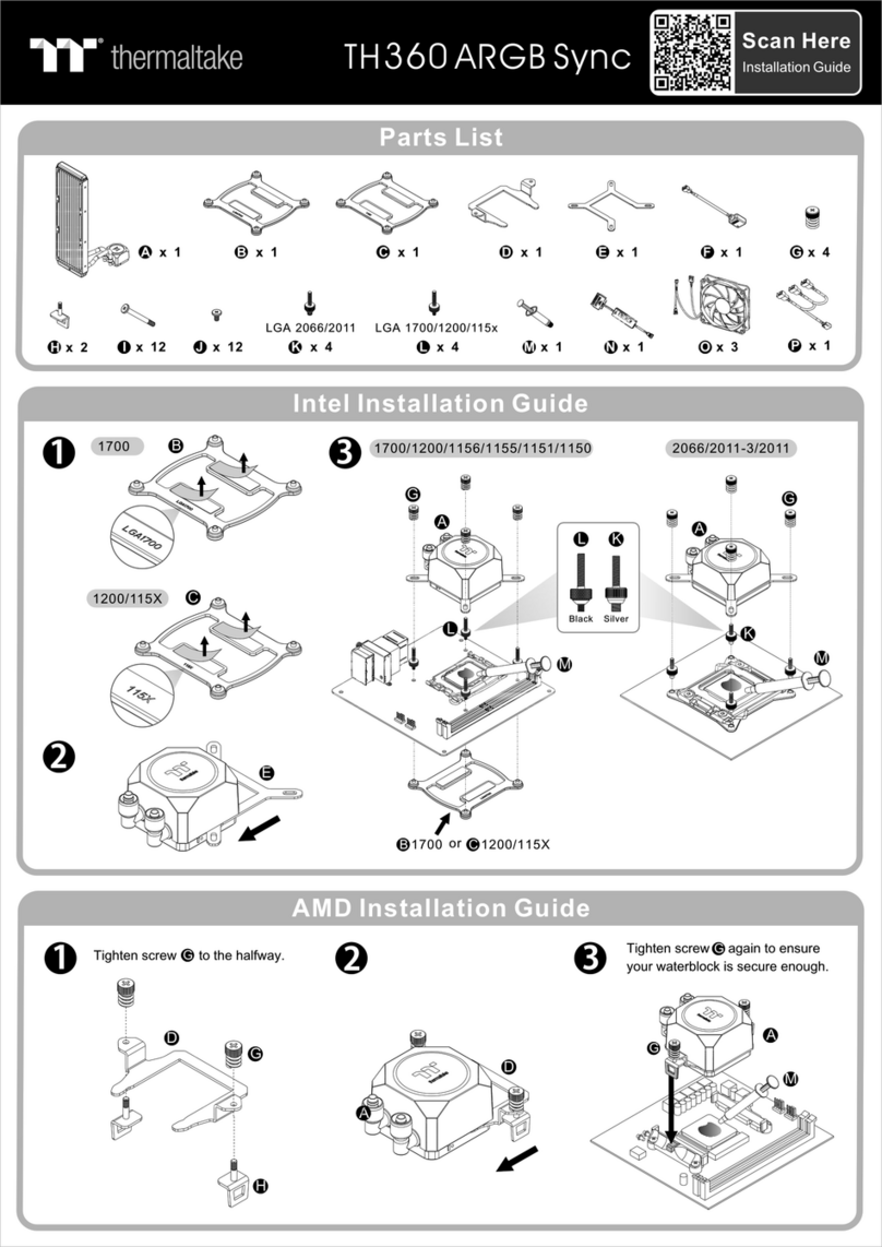
Thermaltake
Thermaltake TH360 ARGB Sync installation guide

Arbor Technology
Arbor Technology EmCORE-v621 Quick installation guide
Siei
Siei ARTDrive EXP-D16 instruction manual
Symetrix
Symetrix 628 Digital Voice Processor Specifications
Joy-it
Joy-it RGB SHIELD quick start guide
