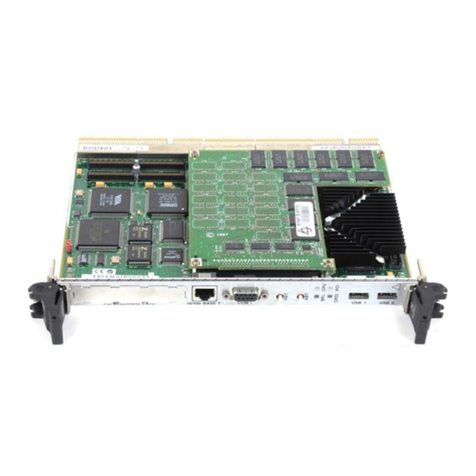
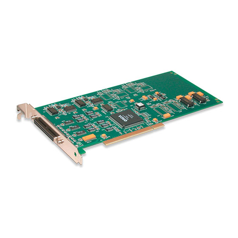
Data Translation DT351 Parts list manual

R
DT351 Getting Started
UM-19138-A
Manual

First Edition
August, 2001
Data Translation, Inc.
100 Locke Drive
Marlboro, MA 01752-1192
(508) 481-3700
www.datatranslation.com
Fax: (508) 481-8620
E-mail: info@datx.com
Copyright © 2001 by Data Translation, Inc.
All rights reserved. No part of this publication
may be reproduced, stored in a retrieval system,
or transmitted, in any form by any means,
electronic, mechanical, by photocopying,
recording, or otherwise, without the prior
written permission of Data Translation, Inc.
Information furnished by Data Translation, Inc.
is believed to be accurate and reliable; however,
no responsibility is assumedby Data Translation,
Inc. for its use; nor for any infringements of
patents or other rights of third parties which
may result from its use. No license is granted by
implication or otherwise under any patent rights
of Data Translation, Inc.
Use, duplication, or disclosure by the United
States Government is subject to restrictions as set
forth in subparagraph (c)(1)(ii) of the Rights in
Technical Data and Computer software clause at
48 C.F.R, 252.227-7013, or in subparagraph (c)(2)
of the Commercial computer Software -
Registered Rights clauseat 48 C.F.R., 52-227-19 as
applicable. Data Translation, Inc., 100 Locke
Drive, Marlboro, MA 01752
Data Translation® is a registered trademark of
Data Translation, Inc. DT-Open LayersTM,
Data Acq SDKTM, Data Acquisition OMNI CDTM,
DT-LV LinkTM, DTx-EZTM, and DT VPITM are
trademarks of Data Translation, Inc.
All other brand and product names are
trademarks or registered trademarks of their
respective companies.

iii
Table of Contents
About this Manual . . . . . . . . . . . . . . . . . . . . . . . . . . . . . . . . . . v
Intended Audience. . . . . . . . . . . . . . . . . . . . . . . . . . . . . . . . . . . . . . . v
How this Manual is Organized . . . . . . . . . . . . . . . . . . . . . . . . . . . . v
Conventions Used in this Manual . . . . . . . . . . . . . . . . . . . . . . . . . vi
Related Information . . . . . . . . . . . . . . . . . . . . . . . . . . . . . . . . . . . . . vii
Where To Get Help. . . . . . . . . . . . . . . . . . . . . . . . . . . . . . . . . . . . . viii
Chapter 1: Overview . . . . . . . . . . . . . . . . . . . . . . . . . . . . . . . . 1
DT351 Key Hardware Features . . . . . . . . . . . . . . . . . . . . . . . . . . . . 2
DT351 Software. . . . . . . . . . . . . . . . . . . . . . . . . . . . . . . . . . . . . . . . . . 3
Getting Started Procedure. . . . . . . . . . . . . . . . . . . . . . . . . . . . . . . . . 4
Chapter 2: Preparing to Use a DT351 Board. . . . . . . . . . . . . 5
Unpacking . . . . . . . . . . . . . . . . . . . . . . . . . . . . . . . . . . . . . . . . . . . . . . 7
Checking the System Requirements . . . . . . . . . . . . . . . . . . . . . . . . 8
Installing the Software. . . . . . . . . . . . . . . . . . . . . . . . . . . . . . . . . . . . 9
Viewing the DT351 Documentation Online. . . . . . . . . . . . . . . . . 11
Chapter 3: Installing the Board . . . . . . . . . . . . . . . . . . . . . . 13
Setting up the Computer. . . . . . . . . . . . . . . . . . . . . . . . . . . . . . . . . 15
Setting up an Expansion Slot . . . . . . . . . . . . . . . . . . . . . . . . . . . . . 16
Inserting the DT351 Board into the Computer. . . . . . . . . . . . . . . 17

Contents
iv
Chapter 4: Loading and Configuring the Device Driver. . . 19
Loading the Device Driver . . . . . . . . . . . . . . . . . . . . . . . . . . . . . . . 21
Windows 98 . . . . . . . . . . . . . . . . . . . . . . . . . . . . . . . . . . . . . . . . 21
Windows Me . . . . . . . . . . . . . . . . . . . . . . . . . . . . . . . . . . . . . . . 22
Windows 2000 . . . . . . . . . . . . . . . . . . . . . . . . . . . . . . . . . . . . . . 22
Configuring the Device Driver. . . . . . . . . . . . . . . . . . . . . . . . . . . . 24
Chapter 5: Attaching a Screw Terminal Panel. . . . . . . . . . . 27
Chapter 6: Wiring Signals. . . . . . . . . . . . . . . . . . . . . . . . . . . 31
Preparing to Wire Signals . . . . . . . . . . . . . . . . . . . . . . . . . . . . . . . . 33
Wiring Recommendations . . . . . . . . . . . . . . . . . . . . . . . . . . . . 33
Screw Terminal Assignments . . . . . . . . . . . . . . . . . . . . . . . . . 34
Wiring Digital Input Signals. . . . . . . . . . . . . . . . . . . . . . . . . . . . . . 35
Wiring Digital Output Signals . . . . . . . . . . . . . . . . . . . . . . . . . . . . 36
Chapter 7: Verifying the Operation of a DT351 Board . . . . 37
Installing the Quick Data Acq Application . . . . . . . . . . . . . . . . . 40
Running the Quick Data Acq Application . . . . . . . . . . . . . . . . . . 42
Performing a Single-Value Digital Input Operation . . . . . . 43
Performing a Single-Value Digital Output Operation. . . . . 43
Index . . . . . . . . . . . . . . . . . . . . . . . . . . . . . . . . . . . . . . . . . . . . .45

v
About this Manual
This manual describes how to set up and install the following
components:
•DT351 software,
•DT351 board, and
•STP37 screw terminal panel.
It also describes how to wire signals to the board and how to verify
the board’s operation using the Quick Data Acq application.
Intended Audience
This document is intended for engineers, scientists, technicians, or
others responsible for setting up a DT351 board to perform data
acquisition operations. It is assumed that you are familiar with the
requirements of your application. It is also assumed that you are
familiar with MicrosoftWindows 98, Windows 2000, or Windows
Me (Millennium Edition).
How this Manual is Organized
This manual is organized as follows:
•Chapter 1, “Overview,”describes the key features of the DT351
hardware and the DT351 software, and provides an overview of
the DT351 getting started procedure.
•Chapter 2, “Preparing to Use a DT351 Board,”describes how to
unpack the DT351 package, check the system requirements,
install the DT351 software, and view the DT351 documentation
online.

About this Manual
vi
•Chapter 3, “Installing the Board,”describes how to install the
DT351 board and load the DT351 Device Driver.
•Chapter 4, “Loading and Configuring the Device Driver,”
describes how to configure the device driver to use interrupts.
•Chapter 5, “Attaching a Screw Terminal Panel,”describes how to
attach and configure the STP37 screw terminal panel.
•Chapter 6, “Wiring Signals,”describes how to wire signals to the
STP37 screw terminal panel.
•Chapter 7, “Verifying the Operation of a DT351 Board,”describes
how to verify the operation of a DT351 board with the Quick
Data Acq application
•An index completes this manual.
Conventions Used in this Manual
The following conventions are used in this manual:
•Notes provide useful information that requires special emphasis,
cautions provide information to help you avoid losing data or
damaging your equipment, and warnings provide information to
help you avoid catastrophic damage to yourself or your
equipment.
•Items that you select or type are shown inbold.
•Courier font is used to represent source code.

About this Manual
vii
Related Information
Refer to the following documents for more information on using the
DT351 board:
•The DT351 User’s Manual (UM-19140). Included on the
Data Acquisition OMNI CDTM provided with the DT351 board,
this manual describes the features of the DT351 board and the
DT351 Device Driver in detail.
•DataAcq SDK User’s Manual (UM-18326). Included on the
Data Acquisition OMNI CD provided with the DT351 board, this
manual describes how to develop your own application program
using the Microsoft C compiler and how to use the DT-Open
LayersDataAcq SDKTM to access the capabilities of Data
Translation®data acquisition boards.
•DTx-EZ Getting Started Manual (UM-15428). This manual
describes how to use the ActiveX controls provided in DTx-EZTM
to access the capabilities of Data Translation data acquisition
boards in Microsoft Visual Basic®or Visual C++®.
•DT VPI User’s Manual (UM-16150). This manual describes how to
use DT VPITM and the Agilent®VEE™visual programming
language to access the capabilities of Data Translation data
acquisition boards.
•DT-LV Link Getting Started Manual (UM-15790). This manual
describes how to use DT-LV LinkTM with the LabVIEW®
graphical programming language to access the capabilities of
Data Translation data acquisition boards.

About this Manual
viii
Where To Get Help
Should you run into problems installing or using a DT351 board, the
Technical Support Department is available to provide technical
assistance. Refer to the DT351 User’s Manual for more information
(refer to page 11 for more information on viewing this manual). If you
are outside the U.S. or Canada,call your local distributor, whose
number is listed in your Data Translation product handbook.

Chapter 1
2
DT351 Key Hardware Features
Ideal for the control of electrical devices and for monitoring digital
signals, the DT351 is an isolated digital I/O board that you can use to
control electrical devices and montior digital signals. It provides the
following major features:
•Half-size board for the PCI bus.
•8 channel-to-channel opto-isolated digital input lines.
•8 channel-to-channel opto-isolated digital output lines.
•DC input signal sensing from 3.5 V to 32 V.
•Output loads of up to 100 mA.
•37-pin shielded I/O connector.
•250 VDC isolation between the inputs and the outputs and
between the digital I/O lines and the system’s PCI bus.
•Over-current fuse protection.
•PCI interrupt-request generated on change of any of the eight
inputs.

Overview
3
1
1
1
1
1
1
1
1
1
DT351 Software
The DT351 software includes the following software components,
which are shipped on the Data Acquisition OMNI CD:
•DT351 Device Driver −You must install and load the device
driver to use a DT351 board with any of the supported software
packages or utilities.
•The Quick Data Acq application −This application provides a
quick way to get a DT351 board up and running. Using the Quick
Data Acq application, you can verify the features of the board,
display data on the screen, and save data to disk.
•DT351 User’s Manual (in PDF format) −Describes the features of
the DT351 board and how to use the DT351 Device Driver with
DT-Open Layers-compliant software to write an application
program.
•This manual (in PDF format).
•Rev 4.0 of Adobe Acrobat Reader −Allows you to view and
print the PDF files.
Refer to page 9 for information on installing the software.

Chapter 1
4
Getting Started Procedure
The flow diagram shown in Figure 1 illustrates the steps needed to
get started using a DT351 board. This diagram is repeated in each
chapter; the shaded area in the diagram shows you where you are in
the getting started procedure.
Figure 1: Getting Started Flow Diagram
Install the Board
(see Chapter 3 starting on page 13)
Wire Signals
(see Chapter starting on page 31)
Verify the Operation of the Board
(see Chapter starting on page 37)
Attach and Configure the
Screw Terminal Panel
(see Chapter starting on page 27)
Prepare to Use a Board
(see Chapter 2 starting on page 5)
Load and Configure the Device Driver
(see Chapter starting on page 19)

5
2
Preparing to Use a
DT351 Board
Unpacking . . . . . . . . . . . . . . . . . . . . . . . . . . . . . . . . . . . . . . . . . . . . . . 7
Checking the System Requirements . . . . . . . . . . . . . . . . . . . . . . . . 8
Installing the Software. . . . . . . . . . . . . . . . . . . . . . . . . . . . . . . . . . . . 9
Viewing the DT351 Documentation Online. . . . . . . . . . . . . . . . . 11

Chapter 2
6
Install the Board
(see Chapter 3 starting on page 13)
Wire Signals
(see Chapter starting on page 31)
Verify the Operation of the Board
(see Chapter starting on page 37)
Attach and Configure the
Screw Terminal Panel
(see Chapter starting on page 27)
Prepare to Use a Board
(this chapter)
Load and Configure the Device Driver
(see Chapter starting on page 19)

Preparing to Use a DT351 Board
7
2
2
2
2
2
2
2
2
2
Unpacking
Open the shipping box and remove the wrapped DT351 board.
Verify that the following items are present:
•DT351 board,
•Data Acquisition OMNI CD.
If an item is missing or damaged, contact Data Translation. If you are
in the United States, call the Customer Service Department at (508)
481-3700. An application engineer will guide you through the
appropriate steps for replacing missing or damaged items. If you are
located outside the United States, call your local distributor, listed in
your Data Translation Product Handbook.
Once you have unpacked your function module, check the system
requirements, as described in the next section.
CAUTION!
Keep the board in its protective antistatic bag until you are
ready to install it; this minimizes the likelihood of electrostatic
damage.

Chapter 2
8
Checking the System Requirements
For reliable operation, your DT351 board requires the minimum
system requirements listed in Table 1.
Once you have verified that your system meets the system
requirements, install the software as described in the next section.
Table 1: Minimum System Requirements
Feature Minimum Requirements
Operating
System Windows 98, Windows 2000, or Windows Me
Processor 80486, Pentium, or compatible
RAM 16 MB or more
CD-ROM Drives One or more
Monitor VGA, or compatible, display (640 x 480 or
higher, 256 colors recommended)

Preparing to Use a DT351 Board
9
2
2
2
2
2
2
2
2
2
Installing the Software
To install the software, perform the following steps:
1. Insert the Data Acquisition OMNI CD into your CD-ROM drive.
2. Click Start from the Task Bar, then click Run.
The Run dialog box appears.
3. In the Command Line edit box, enter D:\LAUNCH.EXE.
If your CD-ROM is not in drive D:, enter the letter of the drive where
your CD-ROM is located.
4. Click OK.
The Data Acquisition Software setup program starts.
5. Click Install Products.
A list of software products that you can install appears.
6. Click Device Drivers.
The DT-Open Layers Data Acquisition software wizard appears.
7. Click Next.
You are prompted for the destination location.
8. Either change the directory path and/or name using Browse or
accept the default directory, then click Next.
You are prompted to select the software components to install.
9. Select DT351, then click Next.
You are prompted for the program folder name.
CAUTION:
This version of the software provides WDM-compliant device drivers
and DLLs (version 5.0 or greater). Other Data Translation boards may
not provide WDM-compliant files.
You cannot use a DT351 board at the same time as another Data
Translation board unless both devices provide WDM-compliant files.

Chapter 2
10
10. Either change the program folder name or accept the default
program folder name, then click Next.
The files are copied to the destination directory.
11. Click Finish.
The DT Data Acquisition Software setup program reappears.
12. Click Main Menu.
13. Click Exit.

Preparing to Use a DT351 Board
11
2
2
2
2
2
2
2
2
2
Viewing the DT351 Documentation Online
Once you have installed the DT351 software, you can view the DT351
documentation by clicking the manual title. You can access the
manuals from the Data Translation, Inc\DT351 program group.
To view the documentation, you need Adobe Acrobat Reader, version
4.0. Here are a few helpful hints about using Adobe Acrobat Reader:
•To navigate to a specific section of the document, click a heading
from the table of contents on the left side of the document.
•Within the document, click the text shown in blue to jump to the
appropriate reference (the pointer changes from a hand to an
index finger).
•To go back to the page from which the jump was made, click the
right mouse button and Go Back, or from the main menu, click
Document, then Go Back.
•To print the document, from the main menu, click File, then
Print.
•To increase or decrease the size of the displayed document, from
the main menu, click View, then Zoom.
•By default, text and monochrome images are smoothed in
Acrobat Reader, resulting in blurry images. If you wish, you can
turn smoothing off by clicking File, then Preferences/General,
and unchecking Smooth Text and Images.

Chapter 2
12
Other manuals for DT351
2
Table of contents
Other Data Translation Computer Hardware manuals
Data Translation
Data Translation DT330 Series User manual
Data Translation
Data Translation DT9835 Parts list manual
Data Translation
Data Translation DT9820 Series Parts list manual

Data Translation
Data Translation DT9835 User manual

Data Translation
Data Translation DT3145 Parts list manual

Data Translation
Data Translation DT9820 Series User manual
Data Translation
Data Translation DT351 User manual

Data Translation
Data Translation DT330 Series Parts list manual
Data Translation
Data Translation DT3120 User manual
Data Translation
Data Translation DT340 Parts list manual

