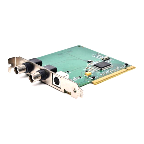
Data Translation DT3145 Parts list manual

DT3145 Getting
UM-19601-B
Started Manual

Second Edition
June, 2003
Data Translation, Inc.
100 Locke Drive
Marlboro, MA 01752-1192
(508) 481-3700
www.datatranslation.com
Fax: (508) 481-8620
E-mail: [email protected]
Copyright © 2003 by Data Translation, Inc.
All rights reserved.
Information furnished by Data Translation, Inc.
is believed to be accurate and reliable; however,
no responsibility is assumed by Data
Translation, Inc. for its use; nor for any
infringements of patents or other rights of third
parties which may result from its use. No license
is granted by implication or otherwise under any
patent rights of Data Translation, Inc.
Use, duplication, or disclosure by the United
States Government is subject to restrictions as set
forth in subparagraph (c)(1)(ii) of the Rights in
Technical Data and Computer software clause at
48 C.F.R, 252.227-7013, or in subparagraph (c)(2)
of the Commercial computer Software -
Registered Rights clause at 48 C.F.R., 52-227-19
as applicable. Data Translation, Inc., 100 Locke
Drive, Marlboro, MA 01752
Data Translationand GLOBAL LABare
registered trademarks and Imaging OMNI CD,
DT Vision Foundry, and DT-Active Camera
Link Frame GrabberTM are trademarks of Data
Translation, Inc.
All other brand and product names are
trademarks or registered trademarks of their
respective companies.

iii
Table of Contents
About this Manual . . . . . . . . . . . . . . . . . . . . . . . . . . . . . . . . . . v
Intended Audience. . . . . . . . . . . . . . . . . . . . . . . . . . . . . . . . . . . . . . . v
What You Should Learn from this Manual. . . . . . . . . . . . . . . . . . . v
Conventions Used in this Manual . . . . . . . . . . . . . . . . . . . . . . . . . vi
Related Information . . . . . . . . . . . . . . . . . . . . . . . . . . . . . . . . . . . . . vi
Where to Get Help . . . . . . . . . . . . . . . . . . . . . . . . . . . . . . . . . . . . . . vii
Chapter 1: Overview . . . . . . . . . . . . . . . . . . . . . . . . . . . . . . . . 1
Key Features . . . . . . . . . . . . . . . . . . . . . . . . . . . . . . . . . . . . . . . . . . . . 2
Supported Software . . . . . . . . . . . . . . . . . . . . . . . . . . . . . . . . . . . . . . 4
Accessories . . . . . . . . . . . . . . . . . . . . . . . . . . . . . . . . . . . . . . . . . . . . . 5
Getting Started Procedure. . . . . . . . . . . . . . . . . . . . . . . . . . . . . . . . . 6
Chapter 2: Preparing to Use the DT3145. . . . . . . . . . . . . . . . 7
Unpacking . . . . . . . . . . . . . . . . . . . . . . . . . . . . . . . . . . . . . . . . . . . . . . 9
Checking the System Requirements . . . . . . . . . . . . . . . . . . . . . . . 10
Installing the Software. . . . . . . . . . . . . . . . . . . . . . . . . . . . . . . . . . . 11
Viewing the DT3145 Documentation . . . . . . . . . . . . . . . . . . . . . . 13
Chapter 3: Installing the Board and Configuring the
Device Driver . . . . . . . . . . . . . . . . . . . . . . . . . . . . . . . . . . . . . 15
Installing the Board . . . . . . . . . . . . . . . . . . . . . . . . . . . . . . . . . . . . . 17
Setting up the Computer . . . . . . . . . . . . . . . . . . . . . . . . . . . . . 17
Selecting an Expansion Slot . . . . . . . . . . . . . . . . . . . . . . . . . . . 18
Configuring the Trigger Selection Jumper. . . . . . . . . . . . . . . 18
Inserting the DT3145 Board in the Computer. . . . . . . . . . . . 21
Loading and Configuring the Device Driver . . . . . . . . . . . . . . . . 23

Contents
iv
Chapter 4: Connecting Signals . . . . . . . . . . . . . . . . . . . . . . 25
Connecting a Camera. . . . . . . . . . . . . . . . . . . . . . . . . . . . . . . . . . . . 28
Connecting Signals to Connector J2 . . . . . . . . . . . . . . . . . . . . . . . 29
Chapter 5: Verifying Board Operation . . . . . . . . . . . . . . . . . 33
Overview . . . . . . . . . . . . . . . . . . . . . . . . . . . . . . . . . . . . . . . . . . . . . . 35
Using DT-AcquireCL . . . . . . . . . . . . . . . . . . . . . . . . . . . . . . . . . . . . 36
Chapter 6: Troubleshooting . . . . . . . . . . . . . . . . . . . . . . . . . 39
General Checklist . . . . . . . . . . . . . . . . . . . . . . . . . . . . . . . . . . . . . . . 41
Service and Support . . . . . . . . . . . . . . . . . . . . . . . . . . . . . . . . . . . . . 46
Telephone Technical Support. . . . . . . . . . . . . . . . . . . . . . . . . . 46
E-Mail and Fax Support . . . . . . . . . . . . . . . . . . . . . . . . . . . . . . 48
World-Wide Web . . . . . . . . . . . . . . . . . . . . . . . . . . . . . . . . . . . . 48
If Your Board Needs Factory Service. . . . . . . . . . . . . . . . . . . . . . . 49
Index . . . . . . . . . . . . . . . . . . . . . . . . . . . . . . . . . . . . . . . . . . . . .51

v
About this Manual
This manual describes how to get started using a DT3145 frame
grabber board.
Intended Audience
This document is intended for engineers, scientists, technicians, or
others responsible for setting up a DT3145 board to perform machine
vision and/or image analysis operations. It is assumed that you are
familiar with the Windows® 2000 or Windows XP operating
environment on the IBMPC or compatible computer platform and
with the operating characteristics of your Camera Link camera.
What You Should Learn from this Manual
This manual will help you install and set up your board and required
software successfully. It is organized as follows:
•Chapter 1, “Overview,” describes the key features of the DT3145
hardware and software, and provides an overview of the getting
started procedure.
•Chapter 2, “Preparing to Use the DT3145,” describes how to
unpack the board and software, check system requirements,
install the DT3145 software, and view the DT3145 documentation
online.
•Chapter 3, “Installing the Board and Configuring the Device
Driver,” describes how to install the DT3145 board and configure
the device driver in Windows 2000 and Windows XP.
•Chapter 4, “Connecting Signals,” describes how to connect the
camera to the board and how to connect signals to the board.
•Chapter 5, “Verifying Board Operation,” describes how to verify
the board’s operation using DT-AcquireCL.

About this Manual
vi
•Chapter 6, “Troubleshooting,” describes how to resolve issues
with the DT3145 board should they occur.
• An index completes this manual.
Conventions Used in this Manual
The following conventions are used in this manual:
• Notes provide useful information that requires special emphasis,
cautions provide information to help you avoid losing data or
damaging your equipment, and warnings provide information to
help you avoid catastrophic damage to yourself or your
equipment.
• Items that you select or type are shown in bold.
•Courier font is used to represent source code.
Related Information
Refer to the following documents for more information on using a
DT3145 board:
•TheDT3145 User’s Manual (UM-19603). This manual
(UM3145.PDF), included on the Imaging OMNI CDTM, describes
the features of the DT3145 board in detail.
•DT-Active Frame Grabber Controls Getting Started Manual
(UM-19336). This manual (DTFG.PDF), included on the Imaging
OMNI CD, describes how to install, set up, and use the
DT-Active Frame Grabber controls (including the DT-Active
Camera Link Frame Grabbercontrol) to develop imaging or
machine vision application programs using MicrosoftVisual
Basic or Microsoft Visual C++.

About this Manual
vii
•GLOBAL LAB Image/2 User’s Manual (UM-17790). This manual
(GLIUM.PDF), included on the Imaging OMNI CD, describes
how to use GLOBAL LAB® Image/2 to create scientific
applications.
•DT Vision Foundry User’s Manual (UM-17755). This manual,
available from Data Translation, describes how to use DT Vision
Foundryto create machine vision applications.
• Camera Link Specification, available from the Automated
Imaging Association (AIA) at http://machinevisiononline.org.
Where to Get Help
Should you run into problems installing or using a DT3145 board, the
Technical Support Department is available to provide technical
assistance. Refer to Chapter 6 starting on page 39 for more
information. If you are outside the United States or Canada, call your
local distributor, whose number is listed in your Data Translation
product handbook.

About this Manual
viii

1
1
Overview
Key Features . . . . . . . . . . . . . . . . . . . . . . . . . . . . . . . . . . . . . . . . . . . . 2
Supported Software . . . . . . . . . . . . . . . . . . . . . . . . . . . . . . . . . . . . . . 4
Accessories . . . . . . . . . . . . . . . . . . . . . . . . . . . . . . . . . . . . . . . . . . . . . 5
Getting Started Procedure. . . . . . . . . . . . . . . . . . . . . . . . . . . . . . . . . 6

Chapter 1
2
Key Features
Key features of the DT3145 frame grabber board are summarized as
follows:
• Operates on the 32-bit, 33 MHz PCI local bus interface.
• Accepts a single Camera Link-compatible digital source
operating in area-scan or line-scan mode.
• Acquires and stores data in single-port format (8-bit, 10-bit,
12-bit, 14-bit, and 16-bit monochrome), dual-port format (8-bit,
10-bit, and 12-bit monochrome), or RGB format (24-bit color).
• In area-scan mode, acquires regions of interest (ROIs), also called
areas of interest or AOIs, that are8to4,096 pixels wide by1 to
4,096 lines high, depending on your camera.
•In line-scan mode, acquires lines that contain 8to 16,384 pixels,
depending on your camera. You can acquire either a single line
or multiple lines to build your own frame.
• Acquires data at frequencies up to 66 MHz, determined by the
Camera Link clock.
• Accepts an external trigger (either isolated or TTL) with
software-selectable polarity.
• Provides two programmable look-up-tables (LUTs), each with
three 256 x 8-bit sections that correspond to input ports
A, B, and C.
• Provides four, software-selectable camera control output signals,
which you can program to output the following:
−An expose output signal to control the exposure time for
asynchronous reset cameras.
−An integration signal to control the exposure time for
line-scan cameras.
−A strobe output signal to control lighting.
−A general-purpose output signal.

Overview
3
1
1
1
1
1
1
1
1
1
• Accepts up to four TTL digital input signals which can generate a
PCI interrupt on a change of state.
• Provides up to four TTL digital output signals.
• Provides an asynchronous, serial communication port for camera
setup.
• Supports overlays.

Chapter 1
4
Supported Software
The following software is available for use with the DT3145 frame
grabber board:
•DT3145 Device Driver – This software is provided on the
Imaging OMNI CD, which is shipped with the board. You must
install this device driver to use a DT3145 board with any of the
supported software packages or utilities. Refer to Chapter 2
starting on page 7 for information on installing the DT3145
device driver.
•DT-Active Camera Link Frame Grabber Control −Use this
ActiveX control, provided on the Imaging OMNI CD, if you want
to develop your own application software for the DT3145 board
using Microsoft Visual Basic or Visual C++ in Windows 2000 or
Windows XP. Refer to Chapter 2 starting on page 7 for
information on installing the DT-Active Camera Link Frame
Grabber Control.
•DT-AcquireCL – Use this software, provided on the Imaging
OMNI CD, to verify the operation of your DT3145 board during
startup. Refer to Chapter 5 starting on page 33 for information on
using DT-AcquireCL.
•GLOBAL LAB Image/2 – Order this optional software package if
you want to develop scientific applications using object-oriented
image processing tools.
•DT Vision Foundry – Order this optional software package if
you want to develop machine vision applications using
object-oriented image processing tools.
Refer to the Data Translation Product Handbook for information on
additional software packages available for the DT3145 board.

Overview
5
1
1
1
1
1
1
1
1
1
Accessories
The following accessories are available for use with the DT3145 frame
grabber board:
•EP327 cable – An integrated cable assembly (2-meter or 5-meter)
that connects the board to your Camera Link camera. You must
order this accessory separately.
•STP15 screw terminal panel – A screw terminal panel that
accepts digital input signals and an external trigger input signal
and provides connections for digital output signals and a strobe
output signal. You must order this accessory separately.
•EP337 cable – A 2-meter cable assembly that is shipped with the
STP15 screw terminal panel. It attaches the STP15 screw terminal
panel to the J2 connector on the DT3145 board.

Chapter 1
6
Getting Started Procedure
The flow diagram shown in Figure 1 illustrates the steps needed to
get started using the DT3145 frame grabber board. This diagram is
repeated in each chapter; the shaded area in the diagram shows you
where you are in the getting started procedure.
Figure 1: Getting Started Flow Diagram
Install the Board and Configure the Device
Driver (see Chapter 3 starting on page 15)
Connect Signals to the Board
(see Chapter 4 starting on page 25)
Verify Board Operation
(see Chapter 5 starting on page 33)
Prepare to Use the DT3145 Board
(see Chapter 2 starting on page 7)
Troubleshoot Issues
(see Chapter 6 starting on page 39)

7
2
Preparing to Use the
DT3145
Unpacking . . . . . . . . . . . . . . . . . . . . . . . . . . . . . . . . . . . . . . . . . . . . . . 9
Checking the System Requirements . . . . . . . . . . . . . . . . . . . . . . . 10
Installing the Software. . . . . . . . . . . . . . . . . . . . . . . . . . . . . . . . . . . 11
Viewing the DT3145 Documentation . . . . . . . . . . . . . . . . . . . . . . 13

Chapter 2
8
Install the Board and Configure the Device
Driver (see Chapter 3 starting on page 15)
Connect Signals to the Board
(see Chapter 4 starting on page 25)
Prepare to Use the DT3145 Board
(this chapter)
Verify Board Operation
(see Chapter 5 starting on page 33)
Troubleshoot Issues
(see Chapter 6 starting on page 39)

Preparing to Use the DT3145
9
2
2
2
2
2
2
2
2
2
Unpacking
Open the shipping box and carefully remove the DT3145 frame
grabber board.
Verify that the following items are present:
• DT3145 frame grabber board, and
• Imaging OMNI CD.
If an item is missing or damaged, call Data Translation's Customer
Service Department at (508) 481-3700 x1394. Customer Service will
guide you through the appropriate steps for replacing missing or
damaged items. If you are located outside the USA, call your local
distributor, listed in your Data Translation Product Handbook.
Note: It is recommended that you save the original packing
material in the unlikely event that your board requires servicing in
the future.
CAUTION:
Keep the DT3145 board in its protective antistatic bag until you are
ready to configure and/or install it.

Chapter 2
10
Checking the System Requirements
For reliable operation, your DT3145 frame grabber board requires the
following minimum system requirements:
• Pentium III processor
• At least one available PCI 32-bit, 33 MHz bus master expansion
slot.
• At least 256 MB of RAM.
• A DirectX-compatible graphics adapter set to 24-bit or 32-bit
color.
• At least one CD-ROM drive.
• Window 2000 or Windows XP.
• If you are using the DT-Active Camera Link Frame Grabber
Control, Microsoft Visual Basic 6.0 or higher or Microsoft Visual
C++ 6.0 or higher.

Preparing to Use the DT3145
11
2
2
2
2
2
2
2
2
2
Installing the Software
To operate properly, the DT3145 frame grabber board requires the
following software components, which are provided on the Imaging
OMNI CD:
• Microsoft DirectX, version 7.0 or greater,
• DT3145 Device Driver, version 1.0 or greater.
Note: If the DirectX software on your computer is less than version
7.0, you are prompted to install the updated DirectX software from
the Imaging OMNI CD.
To install the DT3145-related software from the Imaging OMNI CD,
perform the following steps:
1. Insert the Imaging OMNI CD into your CD-ROM drive.
Typically, the software installation procedure starts automatically. If
the installation procedure does not start automatically, click Run from
the Windows Start menu, either enter x:\LAUNCH.EXE (where x is
the letter of your CD-ROM drive) in the Run dialog box or use the
Browse button to locate LAUNCH.EXE, then click OK.
2. From the main screen, click Install Products.
3. Click MACH II SERIES.
4. Click Install Devices.
5. Click DT3145.
If you do not have an up-to-date version of DirectX installed on your
system, you are prompted to install DirectX software from the Imaging
OMNI CD; afterwards, you must repeat steps 1 to 5. If you do have an
up-to-date version of DirectX, the InstallShield Wizard appears.
6. Click Next.
The license agreement is displayed.

Chapter 2
12
7. Click Yes to accept the license agreement, then click Finish.
You are prompted to choose your destination location.
8. Click Next.
9. Click Typical (which installs the driver, ActiveX control,
examples, and manuals), Compact (which installs only the driver
and ActiveX control), or Custom (which allows you to select the
components to install).
10. Click Next.
11. If you selected Custom, specify the components that you want to
install, then click Next. Otherwise, click Finish.
12. Click Main Menu, then click Exit.
Other manuals for DT3145
1
Table of contents
Other Data Translation Computer Hardware manuals
Data Translation
Data Translation DT351 Parts list manual

Data Translation
Data Translation DT351 User manual
Data Translation
Data Translation DT9820 Series Parts list manual

Data Translation
Data Translation DT9820 Series User manual
Data Translation
Data Translation DT9835 User manual
Data Translation
Data Translation DT340 Parts list manual

Data Translation
Data Translation DT9835 Parts list manual
Data Translation
Data Translation DT300 Series Parts list manual

Data Translation
Data Translation DT330 Series Parts list manual
Data Translation
Data Translation DT330 Series User manual
