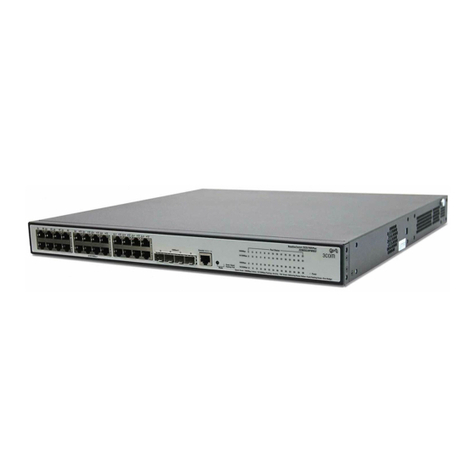
Datacom DM4270 User manual

DM4270
CARRIER ETHERNET SWITCH
INSTALLATION GUIDE
204.4331.03 –October/2019

DM4270 –Installation Guide
Legal Note
204.4331.03 - October/2019
2
LEGAL NOTE
In spite the fact that all the precautions were taken in development of the present
document, DATACOM shall not be held responsible for eventual errors or omissions as
well as no obligation is assumed due to damages resulting from the use of the
information included in this guide. The specifications provided in this guide shall be
subject to changes with no prior notification and are not acknowledged as any type of
contract.
© 2019 DATACOM - All rights reserved.
WARRANTY
DATACOM's products are covered by a warranty against manufacturing defects during a
minimum period of 12 (twelve) months including the legal term of 90 days, as from the
date of issue of the supply Nota Fiscal (Invoice).
Our warranty is standard counter warranty, this means, for exercise of the warranty,
the customer should send the product to DATACOM Authorized Technical Assistance
with paid freight. The return freight of the equipment will be DATACOM responsibility.
To obtain additional information, see our warranty policy in
www.datacom.com.br/en/home
Telephone Number: +55 51 3933-3094

DM4270 –Installation Guide
Contacts
204.4331.03 - October/2019
3
CONTACTS
TECHNICAL SUPPORT
Datacom has available a support portal - DmSupport, to help the customers in use and
config of our equipment.
Access to the DmSupport can be made through link:
https://supportcenter.datacom.com.br
In this site the following are available: firmwares, technical datasheets, config guide,
MIBs and manuals for download. In addition, it allows opening of calls for assistance
with our technical team.
Telephone Number: +55 51 3933-3122
We would like to highlight that our assistance through telephone support is available
from Monday through Friday from 08:00 AM through 05:30 PM.
Important: For support assistance 24x7, please request a quotation to our sales
department.
GENERAL INFORMATION
For any other additional information, please visit the www.datacom.com.br/en/home
or call:
DATACOM
Rua America, 1000
92990-000 –Eldorado do Sul –RS –Brazil
+55 51 3933-3000

DM4270 –Installation Guide
Product Documentation
204.4331.03 - October/2019
4
PRODUCT DOCUMENTATION
ABOUT THIS DOCUMENT
This document is part of a set of documents prepared to provide all necessary
information about DATACOM products.
SOFTWARE PLATFORM
QUICK CONFIGURATION GUIDE –Provides instructions on how to set
the functionalities in a quick manner in the equipment
TROUBLESHOOTING GUIDE –Provides instructions on how to analyze,
identify and solve problems with the product
COMMAND REFERENCE –Provides all the commands related to the
product
RELEASE NOTES –Provides instructions on the new functionalities,
identified defects and compatibilities between Software and Hardware
HARDWARE PLATFORM
DATASHEET –Provides the product technical characteristics
INSTALLATION GUIDE –Provides instructions on the procedures
covering product installation
The availability of some documents can vary depending on the type of product.
Access https://supportcenter.datacom.com.br/ to locate the related documents or
contact the Technical Support for additional information.

DM4270 –Installation Guide
Contents
204.4331.03 - October/2019
5
CONTENTS
LEGALNOTE...............................................................................................................................................................................2
WARRANTY.................................................................................................................................................................................2
CONTACTS..................................................................................................................................................................................3
TECHNICAL SUPPORT......................................................................................................................................................3
GENERAL INFORMATION................................................................................................................................................3
PRODUCT DOCUMENTATION................................................................................................................................................4
ABOUT THIS DOCUMENT ...............................................................................................................................................4
SOFTWARE PLATFORM ..................................................................................................................................................4
HARDWARE PLATFORM .................................................................................................................................................4
CONTENTS..................................................................................................................................................................................5
1INTRODUCING THE HARDWARE INSTALLATION GUIDE......................................................................................7
1.1 ABOUT THIS GUIDE ............................................................................................................................................7
1.2 INTENDED AUDIENCE ........................................................................................................................................7
1.3 CONVENTIONS ......................................................................................................................................................7
2GETTING STARTED..........................................................................................................................................................9
2.1 SAFETY WARNINGS............................................................................................................................................9
3HARDWARE DESCRIPTION......................................................................................................................................... 10
3.1 PRODUCT OVERVIEW ...................................................................................................................................... 10
3.2 MODEL DM4270 24XS+2CX................................................................................................................ 10
3.3 MODEL DM4270 48XS+6CX................................................................................................................ 12
3.4 EQUIPMENT STATUS LEDS........................................................................................................................... 13
3.5 SERIAL CONSOLE INTERFACE (RS-232).............................................................................................. 14
3.6 USB INTERFACE CONSOLE ......................................................................................................................... 14
3.7 USB INTERFACE HOST.................................................................................................................................. 14
3.8 INTERFACE MANAGEMENT ETHERNET (MGMT) ............................................................................. 15
3.9 DATA INTERFACE.............................................................................................................................................. 16
3.10 ALARM INPUT AND OUTPUT ........................................................................................................................ 20
3.11 PSUS AND POWER INPUTS......................................................................................................................... 21
3.12 PROTECTIVE GROUNDING ............................................................................................................................ 25
4DM4270 INSTALLATION.............................................................................................................................................. 27
4.1 DM4270 PACKAGE CONTENT .................................................................................................................. 27
4.2 IDENTIFYING THE PRODUCT ........................................................................................................................ 27
4.3 PREPARING THE INSTALLATION SITE...................................................................................................... 27

DM4270 –Installation Guide
Contents
204.4331.03 - October/2019
6
4.4 19-INCH RACK INSTALLATION ................................................................................................................... 28
4.5 CONNECTING THE PROTECTIVE GROUNDING ...................................................................................... 30
4.6 VENTILATION...................................................................................................................................................... 30
4.7 EQUIPMENT POWER SUPPLY...................................................................................................................... 32
4.8 CHECKING THE PRODUCT’S OPERATION............................................................................................... 33
5INSTALLING AND REMOVING QSFP28/QSFP+/SFP/SFP+ MODULES............................................................. 34
5.1 INSTALLING THE SFP+/SFP MODULES .............................................................................................. 34
5.2 REMOVING SFP+/SFP MODULES.......................................................................................................... 36
5.3 INSTALLING THE QSFP28/QSFP+ MODULES ................................................................................ 36
5.4 REMOVING QSFP28/QSFP+ MODULES............................................................................................ 37
6LOGGING IN FOR FIRST TIME..................................................................................................................................... 39
6.1 MANAGEMENT USING CONSOLE INTERFACE ....................................................................................... 39
6.2 MANAGEMENT USING ETHERNET INTERFACE ..................................................................................... 39
6.3 CONFIGURING USERS..................................................................................................................................... 40
6.4 CHANGING DEFAULT ADMINISTRATOR ACCOUNT PASSWORD ................................................ 41
7TECHNICAL SPECIFICATION....................................................................................................................................... 42
7.1 INTERFACES ........................................................................................................................................................ 42
7.2 POWER SUPPLY AND CONSUMPTION .................................................................................................... 42
7.3 PHYSICAL SPECIFICATIONS......................................................................................................................... 43
7.4 ENVIRONMENT INFORMATION ................................................................................................................... 43
8STANDARDS AND REGULATIONS............................................................................................................................ 44

DM4270 –Installation Guide
Introducing the Hardware Installation Guide
204.4331.03 - October/2019
7
1INTRODUCING THE HARDWARE INSTALLATION GUIDE
1.1 ABOUT THIS GUIDE
This guide provides information about hardware specification and installation
procedures from DM4270 carrier ethernet switch family. This document also covers
initial configuration, those normally needed after hardware installation.
It is assumed that the individual or individuals managing any aspect of this product
have basic understanding of Ethernet and Telecommunications networks.
1.2 INTENDED AUDIENCE
The DM4270 Installation Guide is intended for Network Administrators, technicians and
other qualified service personnel responsible for installing, configuring, planning and
maintaining the DM4270 switch.
1.3 CONVENTIONS
In order to improve the agreement, the following conventions are made throughout this
guide:
1.3.1 Icons Convention
Icon
Type
Description
Note
Notes give an explanation about some topic in the foregoing
paragraph.
Caution
This symbol means that this text is very important and, if
the orientations were not correct followed, it may cause
damage or hazard.
Warning
This symbols means that, case the procedure was not
correctly followed, may exist electrical shock risk.
Warning
Represents LASER radiation. It is necessary to avoid eye and
skin exposure.
Caution
Indicates that equipment, or a part is ESDS (Electrostatic
Discharge Sensitive). It should not be handled without
grounding antistatic wrist strap or equivalent.
Warning
Non-ionizing radiation emission.

DM4270 –Installation Guide
Introducing the Hardware Installation Guide
204.4331.03 - October/2019
8
Note
WEEE Directive Symbol (Applicable in the European Union
and other European countries with separate collection
systems).This symbol on the product or its packaging
indicates that this product must not be disposed of with
other waste. Instead, it is your responsibility to dispose of
your waste equipment by handing it over to a designated
collection point for the recycling of waste electrical and
electronic equipment. The separate collection and recycling
of your waste equipment at the time of disposal will help
conserve natural resources and ensure that it is recycled in
a manner that protects human health and the environment.
For more information about where you can drop off your
consumer waste equipment for recycling, please contact
your local city recycling office or the dealer from whom you
originally purchased the product.
A caution type notice calls attention to conditions that, if not avoided,
may damage or destroy hardware or software.
A warning type notice calls attention to conditions that, if not avoided,
could result in death or serious injury.

DM4270 –Installation Guide
Getting Started
204.4331.03 - October/2019
9
2GETTING STARTED
2.1 SAFETY WARNINGS
Before to continue, read carefully the following safety warnings:
Prior to installation carefully read the whole guide.
Pay attention to the safety instructions during installation, operation or
maintenance of this product. Installation, adjustments or maintenance
must be performed only by qualified, trained and authorized personnel.
To prevent the risk of electrical shocks, before turning the equipment on
or connecting an interface card or cable, install the protective grounding
system.
Before connecting any cable to the equipment, make sure that the
grounding system is functional.
Optical Transceivers used in DM4270 have invisible LASER emitting.
Although all DATACOM homologated transceivers and most of the market
transceivers comply with LASER safety standards, avoid direct contact
and exposure to eyes and skin.
The optical modules use invisible radiation laser transmitters. Although
most SFP/SFP+/QSFP+/QSFP28 on the market meet LASER safety
specifications, never look directly at the terminals of a module or an
optical cord. Exposure to laser emissions may cause partial or total loss
of vision.

DM4270 –Installation Guide
Hardware DESCRIPTION
204.4331.03 - October/2019
10
3HARDWARE DESCRIPTION
This chapter describes the DM4270 line hardware features.
3.1 PRODUCT OVERVIEW
The DM4270 line has two product versions as illustrated below. Both versions are
included in this installation guide.
Figure 1 - DM4270 24XS+2CX
Figure 2 - DM4270 48XS+6CX
3.2 MODEL DM4270 24XS+2CX
Figure 3 - DM4270 24CX+2CX Views

DM4270 –Installation Guide
Hardware DESCRIPTION
204.4331.03 - October/2019
11
Description
1
SLOT PSU1
2
PSU 400 AC Handle
3
PSU 400 AC Power Input
4
PSU 400 AC Status LED
5
PSU 400 AC Insertion and Removal Latch
6
PSU2 SLOT
7
PSU 400 DC Handle
8
PSU 400 DC Power Input
9
PSU 400 DC Status LED
10
PSU 400 DC Knurled nut
11
Ethernet Management Port
12
RS-232 Console Port
13
Alarm interface (2 inputs and 1 output)
14
System ALARM/FAIL LED
15
USB Port Console
16
40/100GE Ethernet LED ports
17
40GE Ethernet LED ports
18
10GE Ethernet ports
19
10GE Ethernet port LEDs
20
40/100GE Ethernet ports
21
40GE Ethernet ports
22
Equipment cooling outlets
23
Host USB Port
24
Auxiliary Safety Grounding
25
Power Supply cooling outlets
Table 1 –DM4270 24XS+2CX Interface Description

DM4270 –Installation Guide
Hardware DESCRIPTION
204.4331.03 - October/2019
12
3.3 MODEL DM4270 48XS+6CX
Figure 4 - DM4270 48XS+6CX Views
Description
1
10GE Ethernet ports
2
40/100GE Ethernet ports
3
System ALARM/FAIL LED
4
10GE Ethernet port LEDs
5
40/100GE Ethernet port LEDs
6
Equipment cooling inlets
7
40/100GE port cooling inlets
8
USB console port
9
Port Ethernet management LEDs
10
USB Host port
11
Ethernet Management Port
12
FAN status LEDs
13
RS-232 console port
14
Auxiliary safety grounding
15
FAN 4 SLOT
16
FAN 3 SLOT
17
FAN 2 SLOT
18
FAN 1 SLOT

DM4270 –Installation Guide
Hardware DESCRIPTION
204.4331.03 - October/2019
13
19
FAN knurled nuts
20
FAN handle
21
PSU 400 AC handle
22
PSU 2 SLOT
23
PSU 400 AC status LED
24
PSU 400 AC insertion and removal latch
25
PSU 400 AC power input
26
PSU 400 DC handle
27
PSU 1 SLOT
28
PSU 400 DC Knurled nut
29
PSU 400 DC power input
30
PSU 400 DC status LED
Table 2 –DM4270 48XS+6CX Interface Description
3.4 EQUIPMENT STATUS LEDS
The DM4270 Switch has two statuses indicating LEDs in the front panel, the LED
ALARM/FAIL located in the Mainboard and the LED PWR located in each PSU. The table
below describes the behavior of the status LEDs of the equipment.
LED PWR
PSU 400 DC
ON GREEN: Indicates that the power supply is running and that
the equipment is powered or on standby ready to take over the
load.
OFF: Power supply with problems or not powered.
PSU 400 AC
ON GREEN: Indicates that the power supply is running and the
equipment is powered or on standby ready to take over the
load.
ON AMBER: Indicates that the power supply is powered, but is
disconnected from the HW or on standby.
OFF: Power supply with problems or not powered.
LED
ALARM/FAIL
OFF: Equipment operating normally, without detected failures
or alarms.
ON RED: Indicates that the equipment is in a state of internal
failure.
ON BLINKING RED (slow): Indicates that the equipment is in a
lower gravity alarm state.
ON BLINKING RED (fast): Indicates that the equipment is in a
lower gravity alarm state.
When the power is connected to the equipment, this LED will turn
red for a short time, and then will turn off.
Table 3 - Status LED behavior

DM4270 –Installation Guide
Hardware DESCRIPTION
204.4331.03 - October/2019
14
3.5 SERIAL CONSOLE INTERFACE (RS-232)
The DM4270 equipment line has a console port for local management. The console port
uses an RJ45 connector. A cable with a male RJ45 connector and a female DB9
connector must be used for the connection to a computer or laptop.
The serial console cable is an accessory included in the DM4270. Additional cables can
be purchased separately via code 710.0137.xx or assembled as described in the
following figures. The pin assignment of the RJ45 connector and its match with the DB9
connector is described in table 4.
Figure 5 –Console Cable
Figure 6 - Console interface connector pin assignment
RJ45 Male
DB9
Female
Function
DM4270 Input/output
1
-
Reserved
-
2
-
Reserved
-
3
2
RS232_TX
Output
4
5
DGND
Ground
5
5
DGND
Ground
6
3
RS232_RX
Input
7
-
Reserved
-
8
-
Reserved
-
Table 4 - Console interface connector pin assignment
3.6 USB INTERFACE CONSOLE
For management via USB, the DM4270 has a USB console port accessible via Mini-USB
cable (not included). On the DM4270 24XS+2CX the port is located on the front panel
and on the DM4270 48XS+6CX the port is located on the rear panel.
The driver for use of this interface in Windows can be found in
http://www.datacom.com.br/support.
3.7 USB INTERFACE HOST
The product provides a type A USB interface host on the rear panel that can operate
according to specification 2.0. There is no need to use this interface during the switch’s

DM4270 –Installation Guide
Hardware DESCRIPTION
204.4331.03 - October/2019
15
installation process. Contact Technical Support for more information on using this
interface.
3.8 INTERFACE MANAGEMENT ETHERNET (MGMT)
The DM4270 has a Gigabit Ethernet interface used for local or remote management of
the switch. For details on how to use it, see the chapter Logging in for First Time. This
interface has two status LEDs whose behavior is described in TABLE 5.
Figure 7 - MGMT LEDs (DM4270 24XS+2CX)
Figure 8 –MGMT Port (DM4270 48XS+6CX)

DM4270 –Installation Guide
Hardware DESCRIPTION
204.4331.03 - October/2019
16
Indicator
Color
Status
Description
LINK/ACT
GREEN
Off
Link Down (inactive port)
On
Link Up (active port)
Blinking
Data sending and/or receiving activity
SPEED
YELLOW
Off
Port operating in 1000Base-T mode
On
Port operating in 10Base-T or 100Base-TX
Table 5 –MGMT Interface LEDs
3.9 DATA INTERFACE
3.9.1 DM4270 48XS+6CX
3.9.1.1 10 Gigabit Ethernet optical SFP+ (10GBase-X) Interfaces
The DM4270 48XS+6CX has 48 10 Gigabit Optical Ethernet interfaces using an SFP+
connector. There are LINK/ACT and SPEED indicator LEDs that are built into the
connectors corresponding to each. The ports are identified by the numbers printed on
the front panel, however, only odd ports (lower ports) are numbered. The numbering of
the other ports follows the order according the figure below:
Figure 9 - 10GbE SFP Ports+ LEDs (DM4270 48XS+6CX)
3.9.1.2 Interface LED indicators 10 Gigabit Optical Ethernet
The convention to indicate the operation and mode of operation of the 10GbE SFP+
interfaces is described in the table below:
Indicator
Color
Status
Description
LINK/ACT
GREEN
Off
Link Down (inactive port)
On
Link Up (active port)
Blinking
Data sending and/or receiving activity

DM4270 –Installation Guide
Hardware DESCRIPTION
204.4331.03 - October/2019
17
SPEED
YELLOW
Off
Port operating in 10GBase-X or 10GBase-T
mode
On
Port operating at a rate lower than 10Gbps
Table 6 - Indicator LEDs of 10GbE SFP+ interfaces
3.9.1.1 40 and 100 Gigabit Optical Ethernet Interfaces
The DM4270 48XS+6CX has 6 high-speed interfaces using QSFP28 connectors.
Figure 10 - 40Gbps and 100Gbps uplink ports
3.9.1.2 40 and 100 Gigabit Optical Ethernet interface LED indicators
The 40GE and 100GE ports have LED indicators of the port operation integrated to the
equipment’s port connectors as shown in figure 10. The convention to indicate the
operation and 40GE and 100GE interface operation mode is described in the table
below:
Indicator
Color
Status
Description
LINK/ACT/
SPEED
GREEN
On
Link Up (active port) operating in 100GBase-
X mode.
YELLOW
On
Link Up (active port) operating at a rate
lower than 100Gbps.
GREEN or
YELLOW
Blinking
Data sending and/or receiving activity
-
Off
Link Down (inactive port)
Table 7 - 40GE and 100GE interface LED indicators

DM4270 –Installation Guide
Hardware DESCRIPTION
204.4331.03 - October/2019
18
3.9.2 DM4270 24XS+2CX
3.9.2.1 10 Gigabit SFP+ Optical Ethernet Interfaces (10GBase-X)
The DM4270 24XS+2CX has 24 10 Gigabit Optical Ethernet interfaces using SFP+
connectors. The status indicating LED contains the LINK/ACT/SPEED information on the
same bicolor LED.
Figure 11 - 10GE SFP+ Port LEDs
3.9.2.2 10 Gigabit Optical Ethernet Interface LED indicators
The convention to indicate the operation and mode of operation of the 10GE SFP+
interfaces is described in the table below:
Indicator
Color
Status
Description
LINK/ACT
/SPEED
GREEN
On
Link Up (active port) operating in
10GBase-X mode.
YELLOW
On
Link Up (active port) operating at a rate
lower than 10GE.
GREEN or
YELLOW
Blinking
Data sending and/or receiving activity
-
Off
Link Down (active port)
Table 8 - 10GE SFP+ Interface LED indicators
3.9.2.3 40 and 100 Gigabit Optical Ethernet Interfaces
The DM4270 24XS+2CX has 4 high-speed interfaces using QSFP+ e QSFP28
connectors.
Due to the equipment’s architecture, there are 3 valid configurations for the uplink
ports:
2 x 40/100 optical Gigabit Ethernet ports (QSFP28)

DM4270 –Installation Guide
Hardware DESCRIPTION
204.4331.03 - October/2019
19
4 x 40 optical Gigabit Ethernet ports (QSFP+).
2 x 40 optical Gigabit Ethernet (QSFP+) + 1 x 40/100 optical Gigabit Ethernet
port (QSFP28).
Figure 12 –40GE and 100GE Uplink Ports
3.9.2.4 Changing the configuration mode of the Uplink ports
In the equipment’s CLI interface, it is possible to change the configuration of the 40GbE
and 100GbE uplink ports with the commands listed below, the change requires a full
system reboot.
To change the uplink operation to 4 x 40GE:
DM4270# card-model 24XS+4QX
Warning: The system will automatically reboot and load the factory
configuration. Once initiated, this process cannot be interrupted.
Proceed with this action? [yes,NO]
To change the uplink operation to 2 x 40/100GE:
DM4270# card-model 24XS+2CX
Warning: The system will automatically reboot and load the factory
configuration. Once initiated, this process cannot be interrupted.
Proceed with this action? [yes,NO]
To change the uplink operation to 2 x 40GE + 1 x 40/100GE:
DM4270# card-model 24XS+2QX+1CX
Warning: The system will automatically reboot and load the factory
configuration. Once initiated, this process cannot be interrupted.
Proceed with this action? [yes,NO]
3.9.2.5 40 and 100 Gigabit Optical Ethernet Interface LED indicators
The 40GE and 100GE ports have LEDs that indicate the operation of the ports on the
left front part of the equipment, as shown in figure 13. The convention to indicate the
operation and the 40GE and 100GE interface operating mode is described in Table 9.

DM4270 –Installation Guide
Hardware DESCRIPTION
204.4331.03 - October/2019
20
Figure 13 –40GE and 100GE port LEDs
Indicator
Color
Status
Type of Port
Description
LINK/ACT/
SPEED
GREEN
On
40/100GE
Link Up (active port)
operating in 100GBase-X
mode.
40GE
Link Up (active port)
operating in 40GBase-X
mode.
YELLOW
On
40/100GE
Link Up (active port)
operating at a rate lower
than 100GE.
40GE
Link Up (active port)
operating at a rate lower
than 40GE.
GREEN or
YELLOW
Blinking
40/100GE and
40GE
Data sending and/or
receiving activity
-
Off
40/100GE and
40GE
Link Down (inactive port)
Table 9 - 40GE and 100GE Interface LED indicators
3.10 ALARM INPUT AND OUTPUT
The DM4270 has two alarm inputs and one alarm output in an RJ45 connector. Alarm 1
and 2 inputs are isolated via optocoupler. External alarm detection occurs when the
Table of contents
Other Datacom Switch manuals
Popular Switch manuals by other brands

Endress+Hauser
Endress+Hauser soliphant II FTM 30 DR operating instructions
NETGEAR
NETGEAR ProSafe GSM7228PS Cli manual
Lindy
Lindy 38243 user manual
TRENDnet
TRENDnet TE100-S32plus Specifications

Dell
Dell S4100-ON Series Setup guide

ZyXEL Communications
ZyXEL Communications EXTRASMART ES-1528 Specifications
