Datacom FVS-1044 User manual

Datacom Systems Inc
Access Your NetworkTM
May 2010 541-0114-U-B.00
FVS-1080 Data Access Switch
USERguide
FVS-1044 Data Access Switch
© 2010 Datacom Systems Inc

This page intentionally left blank

Product Description
DatacomSystems Inc. Filtered VERSAstream™ Data Access Switches are
made to be adaptable. The Filtered Data Access Switchintroduces line-rate
filtering that provides you with the ability to eliminate unwanted traffic fromyour
analysis tools or security sensors. With less data to work with through filtering,
network devices can run faster and more efficiently, which can reduce or
eliminate the possiblityofport oversubscription.
The Filtered VERSAstream™ product provides you with unprecedented
flexibility and filtering capability for your network monitoring needs offering a
complete view ofthe traffic and easily lets security and analysis tools collect all
the data they need, expanding network visibility.

Printed: June 2010 in East Syracuse, New York
All rights reserved. No parts of this work maybe reproduced in anyform or byanymeans - graphic, electronic, or
mechanical, including photocopying, recording, taping, or information storage and retrieval systems - without the written
permission of the publisher.
Products that are referred to in this document maybe either trademarks and/or registered trademarks of the respective
owners. The publisher and the author make no claim to these trademarks.
While everyprecaution has been taken in the preparation of this document, the publisher and the author assume no
responsibilityfor errors or omissions, or for damages resulting from the use of information contained in this document or
from the use of programs and source code that mayaccompanyit.In no event shall the publisher and the author be liable
for anyloss of profit or anyother commercial damage caused or alleged to have been caused directlyor indirectlybythis
document.
Printed: June 2010 in East Syracuse, New York
VERSAstream™
© 2010 Datacom Systems Inc

© 2010 Datacom Systems Inc
5Table of Contents
VERSA ™
stream
Table of Contents
.................................................................................................... 9
Section 1 Terms of Use
........................................................................................ 91 Copyright
........................................................................................ 92 License Agreement
........................................................................................ 93 Trademark Attribution
........................................................................................ 94 Proprietary Notice
........................................................................................ 105 Certifications and Marks
........................................................................................ 106 Safety Notices and Warnings
.................................................................................................... 11
Section 2 Overview
........................................................................................ 111 Shipped Contents
........................................................................................ 122 FVS Features and Benefits
........................................................................................ 133 FVS-1044 Specifications
........................................................................................ 144 FVS-1080 Specifications
.................................................................................................... 15
Section 3 Hardware
........................................................................................ 151 Power
........................................................................................ 152 Any-to-Any Ports
........................................................................................ 163 Management Port
........................................................................................ 164 Serial USB
........................................................................................ 165 Rear Panel
.................................................................................................... 17
Section 4 Initial Configuration
........................................................................................ 171 SERIAL Port Configuration
........................................................................................ 172 IP Address
........................................................................................ 193 Small Form-Factor Plug Module
...................................................................................................... 19
1 Installation Prerequisites
...................................................................................................... 19
2 Safety Guidelines
...................................................................................................... 20
3 Installing the SFP Module
...................................................................................................... 20
4 Removing the SFP Module
.................................................................................................... 21
Section 5 Hardware Installation
........................................................................................ 211 Power
........................................................................................ 212 Management Connection
........................................................................................ 223 Any-to-Any Connection
.................................................................................................... 23
Section 6 FVS Application
.................................................................................................... 24
Section 7 FLOWcontrol™
........................................................................................ 241 Introduction

© 2010 Datacom Systems Inc
Table of Contents6
VERSA ™
stream
...................................................................................................... 25
1 Supported Products
...................................................................................................... 26
2 PC Requirements
...................................................................................................... 26
3 Installation
........................................................................................ 272 FLOWcontrol™ User Interface
...................................................................................................... 27
1 FLOWcontrol Main Screen
..................................................................................................... 27
1 Pull Down Menu Bar
........................................................................................................................................ 28
1 File
........................................................................................................................................ 29
2 Agent
.................................................................................................................................. 29
1 Connect
.................................................................................................................................. 30
2 Disconnect
.................................................................................................................................. 30
3 Communications Console
.................................................................................................................................. 30
4 Add
.................................................................................................................................. 31
5 Delete
.................................................................................................................................. 31
6 Modify
.................................................................................................................................. 31
7 Refresh
.................................................................................................................................. 31
8 Restart
.................................................................................................................................. 31
9 Agent > Add, Modify Properties Form
........................................................................................................................................ 32
3 Utilities
........................................................................................................................................ 34
4 Tabs
........................................................................................................................................ 34
5 Help
.................................................................................................................................. 34
1 About
.................................................................................................................................. 34
2 FLOWcontrol Help
.................................................................................................................................. 35
3 Web Site
.................................................................................................................................. 35
4 Tutorials
..................................................................................................... 35
2 Agent List
...................................................................................................... 36
2 Filter Management
..................................................................................................... 37
1 Saved Filters Panel
..................................................................................................... 38
2 Filter Specifics Panel
........................................................................................................................................ 39
1 Include/Exclude Definition
........................................................................................................................................ 39
2 Include VLAN Tunneling Frames
........................................................................................................................................ 40
3 Rule Definition
........................................................................................................................................ 41
4 Combinatorial Logic
........................................................................................................................................ 44
5 MAC Address Filter
........................................................................................................................................ 44
6 VLAN ID Filter
........................................................................................................................................ 44
7 IPv4 IP Address Filter
........................................................................................................................................ 45
8 IPv4 PORT Number Filter
........................................................................................................................................ 45
9 IPv6 IP Address Filter
........................................................................................................................................ 46
10 Advanced Filter
........................................................................................................................................ 47
11 Context Menus

© 2010 Datacom Systems Inc
7Table of Contents
VERSA ™
stream
........................................................................................................................................ 47
12 Value Specifications
..................................................................................................... 48
3 Advanced Filter Wizard
........................................................................................................................................ 51
1 MAC Address Wizard
........................................................................................................................................ 53
2 VLAN ID Wizard
........................................................................................................................................ 54
3 ETHERtype Wizard
........................................................................................................................................ 55
4 IPv4 IP Address Wizard
........................................................................................................................................ 56
5 IPv4 Protocol Wizard
........................................................................................................................................ 57
6 IPv4 PORT Number Wizard
...................................................................................................... 59
3 Communications Console
..................................................................................................... 59
1 Pull Down Menus
..................................................................................................... 60
2 Console Main Screen
...................................................................................................... 60
4 Product Control
..................................................................................................... 61
1 Product Control Tabs
........................................................................................................................................ 61
1 Configuration Summary
.................................................................................................................................. 62
1 Filtered SINGLEstream Summary
.................................................................................................................................. 62
2 Filtered VERSAstream Summary
........................................................................................................................................ 62
2 Counter Resets
........................................................................................................................................ 63
3 Summary Expanded
........................................................................................................................................ 64
4 Port Configuration
........................................................................................................................................ 66
5 Aggregation Configuration
.................................................................................................................................. 67
1 Example Filtered SINGLEstream
.................................................................................................................................. 69
2 Example Filtered VERSAstream
...................................................................................................... 71
5 Filter Configuration
...................................................................................................... 72
6 Event Log
.................................................................................................... 73
Section 8 Appendix 1 - Command Line Interface (CLI)
........................................................................................ 731 Basic Functionality
........................................................................................ 732 Basic Command Set
...................................................................................................... 73
1 HELP (?)
...................................................................................................... 74
2 CLEAR LOG (CL LOG)
...................................................................................................... 74
3 PASSWORD
...................................................................................................... 75
4 SHOW (SH)
...................................................................................................... 75
5 SHOW DAEMON (SH DN)
...................................................................................................... 76
6 SHOW MANAGEMENT (SH MA)
...................................................................................................... 76
7 SHOW NTP (SH NTP)
...................................................................................................... 76
8 SHOW TIME (SH TI)
...................................................................................................... 76
9 SHOW PORT STATS (SH PO ST)
...................................................................................................... 77
10 SHOW PRODUCT (SH PR)
...................................................................................................... 77
11 SET BAUD (SE BD)
...................................................................................................... 77
12 SET FTP (SE FP)

© 2010 Datacom Systems Inc
Table of Contents8
VERSA ™
stream
...................................................................................................... 78
13 SET DEFAULT IP (SE DEF IP)
...................................................................................................... 78
14 SET IP (SE IP)
...................................................................................................... 79
15 SET SUBNET (SE SU)
...................................................................................................... 79
16 SET GATEWAY (SE GA)
...................................................................................................... 80
17 SET PORT (SE PO)
...................................................................................................... 80
18 SET NTP (SE NTP)
...................................................................................................... 81
19 SET PING (SE PG)
...................................................................................................... 81
20 SET SSH (SE SH)
...................................................................................................... 81
21 SET SYSLOG (SE SY)
...................................................................................................... 81
22 SET TELNET (SE TT)
...................................................................................................... 82
23 SET TFTP (SE TP)
...................................................................................................... 82
24 SET TIME (SE TI)
...................................................................................................... 82
25 REBOOT
...................................................................................................... 83
26 REBOOT -management
...................................................................................................... 83
27 EXIT
.................................................................................................... 84
Section 9 Appendix 2 - Sample Filter Setup
.................................................................................................... 88
Section 10 Customer Service
........................................................................................ 881 World Wide Web
........................................................................................ 882 Warranty
........................................................................................ 893 Limits of Liability
........................................................................................ 894 Force Majeure

9
© 2010 Datacom Systems Inc
Terms of Use
VERSA ™
stream
1 Terms of Use
The following terms and conditions relate to the use ofthis document. Please note that DatacomSystems Inc.
reserves the right, at its entire discretion, to change, modify, add, or remove portions ofthese Terms ofUse at
any time. Please read the Terms ofUse carefully as your use ofthis document is subject to the Terms ofUse
stipulated herein.
1.1 Copyright
Copyright©2007-2010 by DatacomSystems, Inc. Allrights reserved. Printed inthe United States ofAmerica.
No part ofthis publication may be reproduced, stored in a retrievalsystem, or transmitted, in any formor by
any means, electronic, mechanical, photocopying, recording, or otherwise, without the prior writtenpermission
ofDatacomSystems, Inc. To obtain this permission, write to the attention ofthe DatacomSystems legal
department at 9 Adler Drive, East Syracuse, New York 13057-1290, or call315-463-9541.
1.2 License Agreement
Notice To All Users: By using DatacomSystems, Inc. products, you agree to the terms set forth. No licenses,
express or implied, are granted withrespect to the technology described and DatacomSystems, Inc. retains all
rights with respect to the technology described herein. Ifapplicable, you may return the product to the place of
purchase for a fullrefund.
1.3 Trademark Attribution
Access Your Network , DS3 ACTIVEtap , DS3switch , DURAstream , ETHERNETtap , Empowering
Network Professionals , FDDIswitch , FIBERsplitter , FIBERswitch , FIBERSWITCHsystem , FLOW
control , GIGABITswitch , INSERTswitch , INSERTunit , LANswitch , MANAgents ,
MULTINETswitch , NETspan , PERMAlink , PROline , RMON SWITCHINGanalyzer , SINGLE
stream , UNIVERSALswitch , VERSAstream , and WANswitch are trademarks ofDatacomSystems,
Inc. 1ST in Switching Solutions®, DATACOMsystems®, LANclipper®, MANAgents®, and MULTIview®are
registered trademarks ofDatacomSystems, Inc. Allother registered and unregistered trademarks are the sole
property of their respective owners. Allspecifications may be changed without notice.
1.4 Proprietary Notice
This document contains proprietaryinformation about the filtered product family ofproducts and is not to be
disclosed or used except as authorized by written contract withDatacomSystems, Inc.

Terms of Use10
© 2010 Datacom Systems Inc
VERSA ™
stream
1.5 Certifications and Marks
CAUTION: Changes or modifications to this unit not expressly approved by the party responsible for
compliance could void the user’s authority to operate the equipment.
The CE logo indicates that this equipment was tested and found to meet radiated and
conducted emission to the European Community EMC Directive 89/336/EEC requirements as
per EN 61000-6-3:2001, the generic emissions standard for residential, commercialand light
industrialdevices, the limits are those for an EN 55022 Class A product.
This equipment also has beentested and found to meet the immunitylevels for residential, commercialand
light industrialdevices according to EN 61000-6-1:2001, the interference severity levels to the standards
and requirements ofEN 61000-3-2 Harmonic Current, EN 61000-3-3 Voltage Fluctuations and Flicker,
EN 61000-4-2 Electrostatic Discharge, EN 610004-3 Radiated Susceptibility, EN 61000-4-4 Electrical
Fast Transient/Burst, EN 61000-4-5 Surge and EN 61000-4-6 Conducted Susceptibility.
This equipment completed the Product Safety Review and meets the Low Voltage Directive 98/68/EEC
requirements to the standards ofEN 60950 Safety of Information Technology Equipment.
The RoHS compliant logo indicates that this electronic product does not exceed the limit
requirements oftoxic, hazardous substances or elements as set forth in Directive 2002/95/EC
ofthe EuropeanParliament and ofthe Councilof27 January2003 on the restriction ofthe use
of certain hazardous substances in electricaland electronic equipment.
The crossed out wheelie bin logo signifies that the product canbe recycled after being
discarded, and should not be casually discarded as set forth in Directive 2002/96/EC of the
European Parliament and ofthe Councilof27 January 2003 on waste electricaland electronic
equipment (WEEE).
1.6 Safety Notices and Warnings
These explanatory labels are included in this information for the user in accordance
with the requirements of IEC 60825.1.
WARNING: Class 1 laserand LED product. A class 1 laseris safe under all
conditions of normal use. Invisible laser radiation may be emitted from optical
port openings whenno fiber cable is connected, avoidexposure to laser
radiation and do not stare into open optical ports.

11
© 2010 Datacom Systems Inc
Overview
VERSA ™
stream
2 Overview
The Filtered VERSAstream™(FVS) product line increases network visibilityand leverages your investment in
network analyzers, probes, and security equipment by allowing you to simultaneously monitor as many
supported ports as you mayneed to fit your peripheralnetwork tools. Greater visibilityaccelerates problem
resolution, reduces downtime and increases enterprise productivity.
Like allDatacomSystems filtered products, the FVS-1044 and FVS-1080 filtered products are compatible
with allvendor hardware and can be controlled by our FLOWcontrol software, which will allow you to
controlyour filtered product line through a single interface regardless ofwhat network appliances you choose to
deploy.
The Filtered VERSAstream™product line gives you access to your network without creating bottlenecks by
providing the capabilityto monitor, aggregate and filter network traffic to an analysis device or sensor.
Aggregation combines two or more streams of network traffic into one link. Aggregated network traffic may
overload or oversubscribe an analysis device. Filtering unwanted network traffic reduces the potential for
oversubscribing. The Filtered VERSAstream™product line features hardware based, line-rate filtering. This
allows you to eliminate unwanted network traffic from analysis tools or sensors. Filtering also gives you the
ability to deploy lower speed tools on higher speed networks.
2.1 Shipped Contents
FVS-1044 filtered product
1 — Model:FVS-1044
2 — AC Line Cords
1 — FLOWcontrol™software
1 — DRL434-6-R cable, USB type A to DB9 F
1 — DRL366-3-R cable, RJ45 to RJ45
FVS-1080 filtered product
1 — Model:FVS-1080
2 — AC Line Cords
1 — FLOWcontrol™software
1 — DRL434-6-R cable, USB type A to DB9 F
1 — DRL366-3-R cable, RJ45 to RJ45

Overview12
© 2010 Datacom Systems Inc
VERSA ™
stream
2.2 FVS Features and Benefits
Apply port levelpacket filtering to SPAN monitoring solutions.
Line-rate filtering eliminates unwanted traffic fromanalysis tools or security sensors.
Load balancing eliminates bottlenecks and port over subscription.
Filter network traffic to any monitoring port based upon IP address, port number, MAC address,
VLAN, protocoltype or customizable offsets in the IP header.
"Any-to-Any" architecture can send traffic fromany input ports to any monitoring ports.
"Many-to-Any"architecture combines traffic fromup to four ofthe input ports, providing visibility into
multiple network segments with one monitoring tool.
"One-to-Many"architecture allows sending multiple copies ofdata fromthe input port to multiple
monitoring devices.
Aggregate and reassembly fullduplex conversations frommultiple trunk links, redundant networks,
Ether Channel, load balanced servers and asymmetrically routed traffic.
Simultaneously monitor data at multiple points onthe network withthe same set ofdevices.
DatacomCustomer Service Support is available via:
Phone:(315) 463-9541
Fax:(315 ) 463-9557
E-mail:support@datacomsystems.com
Website:www.datacomsystems.com

13
© 2010 Datacom Systems Inc
Overview
VERSA ™
stream
2.3 FVS-1044 Specifications
Network Ports (front):
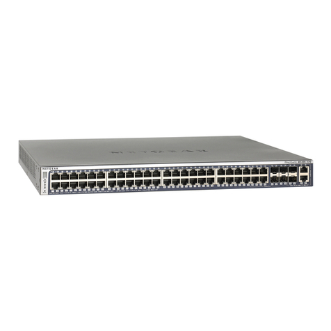
4 - 10/100/1000BaseT (RJ45 Connectors) or SFP*
*SFP = Small Form Pluggable canbe LX or SX
Monitor Ports (front):
4 - 10/100/1000BaseT (RJ45 Connectors) or SFP*
*SFP = Small Form Pluggable canbe LX or SX
Management Port (front):
RJ45 @ 10/100 Mbs Full-Duplex
Serial Port (front):
USB-type A style
Power:
Input: 120-240VAC 50-60Hz, 0.6A-0.3A
Dimensions (H x W x D): includes mount bracket
1.75 x19.00 x12.00 inch
4.44 x48.26 x30.48 cm
Weight:
7.0 lbs; shipping: 14.0 lbs
3.175 kg; shipping; 6.3 kg
Operating Temperature:
32º to 104° F
0ºto 40° C
Storage Temperature:
-22º to 149° F
-30º to 65° C
Humidity:
Less than95° C non-condensing
Warranty:
One (1) year - see 'Warranty' sectionfor details.
88

Overview14
© 2010 Datacom Systems Inc
VERSA ™
stream
2.4 FVS-1080 Specifications
Network or Monitor Ports (front):
8 - 10/100/1000BaseT (RJ45 Connectors) or SFP*
*SFP = Small Form Pluggable canbe LX or SX
Management Port (front):
RJ45 @ 10/100 Mbs Full-Duplex
Serial Port (front):
USB-type A style
Power:
Input: 120-240VAC 50-60Hz, 0.6A-0.3A
Dimensions (H x W x D): includes mount bracket
1.75 x19.00 x12.00 inch
4.44 x48.26 x30.48 cm
Weight:
7.0 lbs; shipping: 14.0 lbs
3.175 kg; shipping; 6.3 kg
Operating Temperature:
32º to 104° F
0ºto 40° C
Storage Temperature:
-22º to 149° F
-30º to 65° C
Humidity:
Less than95° C non-condensing
Warranty:
One (1) year - see 'Warranty' sectionfor details.
88

15
© 2010 Datacom Systems Inc
Hardware
VERSA ™
stream
3 Hardware
This section provides an illustration and description ofthe FVS series product:
FVS-1044
FVS-1080
An explanation of each front panellegend follows:
3.1 Power
Two AC power sources are provided for the filtered product unit. Although only one power source is required
to power the module, use ofa second independent power source is strongly recommended to assure
uninterrupted monitoring. Furthermore, connecting the second AC input power socket to a different external
power source circuit than the first AC input power source eliminates power as a single point offailure. The
power sockets are located on the rear.
The POWER 1 and 2front panelLEDs illuminate green when power is available at both of the two rear power
sockets indicating power 1 and 2, respectively, are on. Either LED not illuminated indicates immediate
investigation is recommended ifboth power sources are being used and a power led is not illuminated to insure
redundant power integrity.
3.2 Any-to-Any Ports
SFP or RJ45 — SFPare SmallFormPluggable (canbe LX or SX) or RJ45 are RJ45 connectors used for
connection to network segments or analysis tools. Betweenthe connectors are LEDs that display line status and
line speed ofeachport. A solid light indicates the Fiber SFP or RJ45 10/100/1000BaseT port is connected. A
blinking light indicates the presence oftraffic.

Hardware16
© 2010 Datacom Systems Inc
VERSA ™
stream
3.3 Management Port
The MANAGEMENT PORT is an RJ45 socket used for 10/100 Mbs fixed full-duplex connection with a straight-
through LAN cable via your management LAN to a Remote Management Console which is a standard PC
running FLOWcontrol .
Link indicates connection. The LED Display Code table deciphers the RJ45 jacks withintegrated LEDs that
displayline status ofthe MANAGEMENT PORT.
3.4 Serial USB
The SERIAL connector port is a shielded USB type A Female and is cabled to the COM port of any compatible
network toolor PC where FLOWcontrol Software resides. It is the only port that can easily connect the
Management PC to set the IP address for the first time.
3.5 Rear Panel
Two AC input power sockets are provided on the rear panel.The POWER 1 and 2front panelLEDs illuminate
green whenpower is available at both ofthe two rear power sockets indicating power 1 and 2, respectively,
are on. Either front panelLED not illuminated indicates immediate investigation is recommended ifbothpower
sources are being used and a power led is not illuminated to insure redundant power integrity.
Although only one AC power source is required to power the filtered product unit, use ofa second independent
power source is strongly recommended to assure uninterrupted monitoring. Furthermore, connecting the second
AC input power socket to a different externalpower source circuit than the first AC input power source
eliminates power as a single point offailure.

17
© 2010 Datacom Systems Inc
Initial Configuration
VERSA ™
stream
4 Initial Configuration
IMPORTANT: Review the following section prior to initial configuration of the hardware.
IMPORTANT: Detailed Command Line Interface (CLI) syntax information is found in the 'Appendix
1 - Command Line Interface (CLI) ' section.
Initialconfiguration is performed directly with a terminal emulation application on a management PC connected
to the FVS through the SERIAL USB-style type A port. After initialconfiguration, the FVS canbe remotely
operated though the MANAGEMENT RJ45 port. Only one configuration session can be open at a time.
4.1 SERIAL Port Configuration
Once the FVS SERIAL port hardware connection is made, open the terminal emulator application on the
management PC and create a connection with the settings that fit your needs:
FVS-1044
FVS-1080
2400 bits persecond
9600 bits persecond
8 data bits
8 data bits
Parity none
Parity none
1 stop bit
1 stop bit
Flowcontrol none
Flowcontrol none
4.2 IP Address
AllFVS filtered products are assigned an IP address (192.168.1.1) by default. You must change the IP
address to match your network.
NOTE: Ifyour FVS already has an IP address for your network, you may proceed to the 'SmallForm-Factor
Plug Module ' section.
Step 1. First, connect your terminalemulator application PC and FVS using the provided DatacomSystems
DRL434-6-R cable. Connect the DB9 Female pin end to the serialport on your PC and connect the USB-
style Type A end to the SERIAL port on the unit.
NOTE: For PCs without 9-pin serialports, check with you product representative for available sources
ofa USB to RS-232 Plug-in Adapter.
Step 2. Open the terminalemulator application on your PC.
Step 3. Create a seriallink by selecting the COM port assigned to the serialport on your PC.
Step 4. Next, configure the COM Properties. The initialcorrect setting to communicate with the FVS series
product (9600, 8, None, 1, None) are shown below. Once allsettings are configured correctly, you can
connect to your Filtered VERSAstream™product.
Step 5. Next, plug the FVS into the externalpower source using the supplied AC line cord. Note that either
POWER 1 or 2LED is illuminate green indicating power is available at the rear AC power socket to which the
AC Line Cord is connected. The other POWER LED is not illuminated, indicating a lack ofpower to the
unconnected AC power socket.
73
19

Initial Configuration18
© 2010 Datacom Systems Inc
VERSA ™
stream
Prior to proceeding any command line entry, observe the following serialstartup screen activity that willlast for
approximately one and a halfto two minutes:
DipSwitch Status = 0xFF
Enabling DatacomRS232 serialport.
DatacomSystems, Inc. FVS-1080
Starting Self Tests.....
Memory Tests Pass!
Located Datacom512MB DDR
*
*
*
Booting Operating System.....please wait.....
VERSAstreamInitialization In Process....
Restoring Settings...
VERSAstreamActive...
The FVS is now ready to accept command line entry commands.
Step 6. Hit the Enter key twice in succession (i.e., Enter, Enter) to display the username: prompt. The CLI
username and password are case-sensitive. The default values are:
username:Administrator
password:admin
> ?and press the Enter key to see available commands list, details in 'Basic Command Set ' section.
Step 7. Separate IP, Subnet or GatewayCLI entries ARE NOT ALLOWED for the FVS-1080. 'Set IP
Address ' by typing SET IP ppp.ppp.ppp.ppp sss.sss.sss.sss ggg.ggg.ggg.ggg where ppp.ppp.ppp.ppp
corresponds to a valid IP address, where sss.sss.sss.sss corresponds to a valid SUBNET for your network and
where ggg.ggg.ggg.ggg corresponds to a valid GATEWAY for your network. Press the Enter key to continue.
Step 8. Review and verify the network address settings are correct and enter (y) to confirmchanges (updating
elapsed time approximately15 seconds) otherwise enter (n) to canceland repeat Step 7.
Step 9. Follow the screenprompts and at the command prompt, type 'REBOOT -management 'to allow the
new network setting to take effect.
Step 10. Follow the screenprompts and after the screenresponse VERSAstream Active . . . (elapsed time
approximately 35 seconds) type 'SH MA 'to review the network address settings. Verify settings are correct.
Step 11. Type 'EXIT ' and press the Enter key to end the connection session indicated by 'Closing
Connection . . . ' response, thenclose the terminalemulationapplication.
Step 12. Disconnect the DRL512-2M-R serialcable fromyour FVS series product and proceed to installthe
FVS series product in your chosen network location.
73
78
83
76
83

19
© 2010 Datacom Systems Inc
Initial Configuration
VERSA ™
stream
4.3 Small Form-Factor Plug Module
This section provides information about smallform-factor plug (SFP) modules. The SFP modules are input/
output devices that plug into a Gigabit Ethernet (GE) smallform-factor (SFF) port, linking the port witha
1000Base-X fiber.
The fiber SFP module have a receiver port (Rx) and a transmitter port (Tx) that make up one opticalinterface.
The 1000Base-SX (short wavelength) SFP module operates on standard multimode fiber networks compliant
withthe 1000Base SX standard. The 1000Base-LX (long wavelength) SFP module operates onstandard
single-mode fiber networks compliant withthe 1000Base LX standard. The fiber SFP module is a 1000 Mbps
opticalinterface in the formof an LC-type duplex port that supports interfaces compliant with the 1000Base-X
standard.
4.3.1 Installation Prerequisites
This section describes safety and compliance guidelines you should observe before you install an SFP module in
your FVS unit.
NOTE: You can installand remove SFP modules with power on to the system; however, it is strongly
recommended that you do not installor remove the SFP module withfiber or copper cables attached to it.
Disconnect allcables before removing or installing a SFP module.
CAUTION: Prevent systemproblems, use only DatacomSystems Inc. supplied SFP modules.
4.3.2 Safety Guidelines
Before handling a SFP module, observe the following guidelines:
Copper and fiber SFP modules are static-sensitive. To prevent electrostatic discharge (ESD) damage, follow
your normalESD handling procedures.
Fiber SFP modules are dust-sensitive. When storing a SFP module or when a fiber cable is not plugged in,
always keep plugs in the SFP module opticalhole.
The most common source ofcontaminants inthe fiber SFP opticalaperture is debris picked up on the
terminations ofthe opticalconnectors. Use an alcoholswab or lint-free absorbent wipes to cleanthe
terminations of the opticalconnector.
WARNING: Fiber SFP modules are class 1 laser and LED products. Invisible laserradiation may be
emitted from the port opening when no fibercable is connected, avoid exposure to laser radiation and
do not stare in open optical ports.

Initial Configuration20
© 2010 Datacom Systems Inc
VERSA ™
stream
4.3.3 Installing the SFP Module
SFP modules might ship alreadyinstalled in your FVS or they might arrive packaged separately. This section
describes how to installthe SFP module.
NOTE: You can installSFP modules with power on to the system; however, it is strongly recommended that
you do not installthe SFP module withfiber or copper cables attached to it. Disconnect allcables before
installing a SFP module.
CAUTION: Prevent systemproblems, use only DatacomSystems Inc. supplied SFP modules.
Step 1. Turnthe SFP module so the latchis towards the center ofthe Gigabit Ethernet Interface sockets. The
SFP module is keyed so that it cannot be inserted incorrectly.
Step 2. Insert the SFP module into the SFF port and repeat Step 1 and Step 2 inserting other SFP modules
untilcompleted.
Step 3. Attachthe appropriate network cable to the LC-type or RJ45-type connector onthe SFP module. For
fiber optic SFP modules you can use either simplex or duplex connectors. For simplex connectors, two cables
are required, one cable for transmit (Rx) and a second cable for receive (Rx). For duplexconnectors, only one
cable that has both Tx and Rx connectors is required.
4.3.4 Removing the SFP Module
SFP modules might ship alreadyinstalled in your FVS or they might arrive packaged separately. This section
describes how to remove the SFP module.
NOTE: You can remove SFP modules with power on to the system; however, it is strongly recommended that
you do not remove the SFP module withfiber or copper cables attached to it. Disconnect allcables before
removing a SFP module.
Step 1. Disconnect the network cable fromthe SFP module LC-type or RJ45-type connector.
Step 2. Release the SFP module fromthe GE SFF port by moving the swing latch away fromthe body ofthe
unit.
Step 3. Slide the SFP module out ofthe GE SFF port.
This manual suits for next models
1
Table of contents
Other Datacom Switch manuals
