Datacom DM4170 Series User manual

INSTALLATION MANUAL
CARRIER ETHERNET SWITCH
204.4308.03
DM4170

DM4170 –Installation Manual
Installing the DM4170
204.4308.03
2
LEGAL NOTICE
Despite all precautions having been taken in the preparation of this document, DATACOM
does not assume any responsibility for any possible errors or omissions, as well as no liability
is assumed for damages resulting from the use of the information contained in this manual.
The specifications provided in this manual are subject to changes without prior notice and
are not recognized as any type of contract.
© 2019 DATACOM –All Rights Reserved
WARRANTY
This product is guaranteed against material and manufacturing defects for the period
specified in the sales invoice.
The warranty only includes the repair and replacement of components or defective parts at
no charge to the customer. Defects resulting from the following are not covered: improper
use of the equipment, electric power failure, natural phenomena (lightning discharges, for
instance), failure of equipment connected to this product, installations with improper
grounding or repairs carried out by personnel not authorized by DATACOM.
This warranty does not cover repairs at the customer's facilities. The equipment must be sent
to DATACOM to be repaired.

DM4170 –Installation Manual
Installing the DM4170
204.4308.03
3
CONTACTS
TECHNICAL SUPPORT
DATACOM provides a call center for technical support during the configuration and use of
the equipment, in addition to providing technical assistance for repairs and maintenance.
Email: suporte@datacom.ind.br
Phone: +55 51 3933-3122
Website: http://www.datacom.ind.br/en/support
GENERAL INFORMATION
For any additional information, please go to http://www.datacom.ind.br/en/ or contact:
DATACOM
Rua América, 1000
ZIP code: 92990-000 –Eldorado do Sul –RS –Brazil
+55 51 3933-3000

DM4170 –Installation Manual
Installing the DM4170
204.4308.03
4
PRODUCT DOCUMENTATION
This manual is part of a documentation set prepared to provide all necessary information
about Datacom products.
•Datasheet –Presents product data and features.
•DmOS Command Reference –Lists all commands that are relevant to the products
(English only).
•Installation Manual –Provides orientation about product installation procedures.
•Quick Reference Guide –Provides summarized instructions for the product's
installation and configuration procedures.
•Release Notes –Informs users about new features, known bugs and hardware
compatibility.
The availability of certain documents may vary depending on the type of product.
Visit the DATACOM website to find related documentation or contact Technical Support for
more information (see CONTACTS).

DM4170 –Installation Manual
Installing the DM4170
204.4308.03
5
TABLE OF CONTENTS
LEGAL NOTICE ..........................................................................................................................................................................2
WARRANTY................................................................................................................................................................................2
CONTACTS .................................................................................................................................................................................3
TECHNICAL SUPPORT...............................................................................................................................................................3
GENERAL INFORMATION.........................................................................................................................................................3
PRODUCT DOCUMENTATION............................................................................................................................................4
TABLE OF CONTENTS.............................................................................................................................................................5
1INTRODUCING THE PRODUCT’S INSTALLATION MANUAL ......................................................................7
ABOUT THIS MANUAL ................................................................................................................................................7
TARGET AUDIENCE......................................................................................................................................................7
CONVENTIONS............................................................................................................................................................7
1.3.1 Icons.......................................................................................................................................................................7
1.3.2 TEXTS..............................................................................................................................................................................8
2GETTING STARTED.....................................................................................................................................................9
SAFETY WARNINGS.....................................................................................................................................................9
PRODUCT OVERVIEW..................................................................................................................................................9
3HARDWARE DESCRIPTION..................................................................................................................................10
DM4170 24GX+12XS ........................................................................................................................................10
DM4170 24GX+4XS+2QX ...............................................................................................................................11
EQUIPMENT STATUS LEDS.....................................................................................................................................11
SERIAL CONSOLE INTERFACE (RS-232)................................................................................................................12
USB INTERFACE CONSOLE.....................................................................................................................................13
USB HOST INTERFACE............................................................................................................................................13
ETHERNET MANAGEMENT INTERFACE (MGMT) ................................................................................................13
DATA INTERFACES ...................................................................................................................................................14
3.8.1 SFP Optical Ethernet Gigabit Interfaces (1000Base-X).....................................................................14
3.8.2 SFP+ Ethernet 10 Gigabit Optical Interfaces (10GBase-X).............................................................15
3.8.3 QSFP+ Ethernet 40 Gigabit Optical Interfaces (40GBase-X)..........................................................15
ALARM INPUT AND OUTPUT..................................................................................................................................16
PSUS AND POWER INPUTS....................................................................................................................................17
3.10.1 Pin Settings and Polarity ........................................................................................................................19
3.10.2 Power Cables ..............................................................................................................................................20
PROTECTIVE GROUNDING ......................................................................................................................................21
4DM4170 INSTALLATION.......................................................................................................................................22
PREPARING THE INSTALLATION SITE......................................................................................................................22
4.1.1 Installation site requirements....................................................................................................................22

DM4170 –Installation Manual
Installing the DM4170
204.4308.03
6
4.1.2 Environment requirements.........................................................................................................................22
4.1.3 Equipment requirements............................................................................................................................22
DM4170 PACKAGE CONTENT..............................................................................................................................22
IDENTIFYING THE PRODUCT ...................................................................................................................................22
19-INCH RACK INSTALLATION ...............................................................................................................................23
CONNECTING THE PROTECTIVE GROUNDING .............................................................................................23
VENTILATION ...........................................................................................................................................................24
PRODUCT POWER SOURCE ....................................................................................................................................24
4.7.1 Connecting the PSU 125.............................................................................................................................24
4.7.2 Connecting to Power Supply.....................................................................................................................25
CHECKING THE PRODUCT’S OPERATION ...............................................................................................................25
5INSTALLING AND REMOVING SFP/SFP+/QSFP+ MODULES.................................................................26
INSTALLING SFP/SFP+ MODULES .......................................................................................................................27
REMOVING SFP/SFP+ MODULES........................................................................................................................28
6ACCESSING THE PRODUCT.................................................................................................................................29
MANAGEMENT THROUGH THE CONSOLE INTERFACE..........................................................................................29
MANAGEMENT THROUGH THE ETHERNET OUTBAND INTERFACE (MGMT) ...................................................29
MANAGEMENT ACCESS CONFIGURATION ............................................................................................................29
7TECHNICAL SPECIFICATIONS.............................................................................................................................31
INTERFACES ..............................................................................................................................................................31
POWER SUPPLY SPECIFICATIONS...........................................................................................................................31
POWER SUPPLY AND OUTPUT ...............................................................................................................................32
PHYSICAL SPECIFICATIONS .....................................................................................................................................32
ENVIRONMENTAL INFORMATION..........................................................................................................................32

DM4170 –Installation Manual
Installing the DM4170
204.4308.03
7
1INTRODUCING THE PRODUCT’S INSTALLATION MANUAL
ABOUT THIS MANUAL
This manual can be used for the DM4170 switches, providing information about the
installation of this product line.
The document focuses on the electrical and physical part, indicating the states of the
equipment as well as the installation of its hardware. It is assumed that the individual or
individuals who will manage any aspect of the product have basic knowledge of electrical
installations, Ethernet interfaces and general telecommunications knowledge.
TARGET AUDIENCE
This manual is intended for network administrators, technicians or qualified personnel
responsible to install, configure, plan and maintain this product.
CONVENTIONS
To facilitate understanding throughout this manual the following conventions have been
adopted:
1.3.1 Icons
Icon
Category
Description
Note
Notes better explain certain details presented in the text.
Caution
This formatting indicates that the text contained herein is of
great importance and there is a risk of damage.
Warning
Indicates that if the procedures are not followed correctly, there
is a risk of electric shock.
Warning
Indicates the presence of laser radiation. If the instructions are
not followed and direct exposure to the skin and eyes is not
avoided, it may cause damage to the skin or impair vision.
Caution
Indicates equipment or part that is sensitive to static electricity.
It should not be handled without grounding antistatic wrist
strap or equivalent.
Warning
Indicates the emission of non-ionizing radiation.
Note
Symbol of the WEEE directive (Applicable for European Union
and other countries with selective collection system). This
symbol on the product or on packaging indicates that the
product cannot be disposed of with household waste. However,
it is your responsibility to take the equipment to be disposed of
at a collection point designated for the recycling of electrical
and electronic equipment. Separate collection and recycling of
equipment at the time of disposal help preserve natural
resources and ensure that equipment is recycled so as to protect

DM4170 –Installation Manual
Installing the DM4170
204.4308.03
8
Icon
Category
Description
people's health and the environment. For more information on
where to discard equipment for recycling, contact your local
dealer where the product was purchased.
Table 1 –Icon Conventions
A caution type notice calls attention to conditions that, if not avoided, may
damage or destroy hardware.
A warning type notice calls attention to conditions that, if not avoided, can result
in death or serious injury.
1.3.2 Texts
Convention
Description
Hyperlink
Indicates an Internet site or e-mail address. It can also be used
to indicate a link within the document itself (e.g. a chapter)
Terminal
System commands and terminal outputs
Object
Indicates a reference to something. Used to emphasize a
referenced object.
[Key]
Keyboard buttons
Table 2 –Text conventions
The conventions used in this document are not necessarily the same as those in
the Command Reference document. Observe the conventions established for
each document.

DM4170 –Installation Manual
Installing the DM4170
204.4308.03
9
2GETTING STARTED
SAFETY WARNINGS
Before proceeding, carefully observe the following safety warnings:
Before installation, the entire manual must be read carefully. If you have any
questions, you should contact the authorized technical support.
Pay attention to the safety instructions during the installation, operation and
maintenance of this product. The installation, operation and maintenance
procedures should preferably be performed by qualified and trained personnel
authorized to carry out such tasks.
To prevent the risk of electric shocks, before connecting the equipment or
connecting cables, ensure the installation and operation of a grounding system.
Optical modules use invisible radiation laser transmitters. Although most
SFP/SFP+/QSFP+ on the market meet LASER safety specifications, never look
directly at the terminals of a module or an optical cord. Exposure to laser
emission may cause partial or total loss of vision.
PRODUCT OVERVIEW
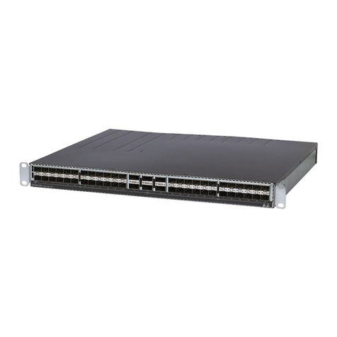
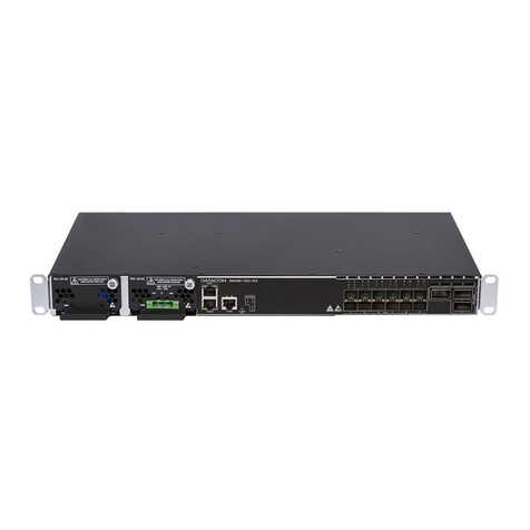
The DM4170 product line has two product versions as illustrated below. Both versions are
covered by this installation guide.
Figure 1 - DM4170 24GX+12XS
Figure 2 - DM4170 24GX+4XS+2QX

DM4170 –Installation Manual
Installing the DM4170
204.4308.03
10
3HARDWARE DESCRIPTION
This chapter describes the DM4170 line’s hardware features.
DM4170 24GX+12XS
Figure 3 - DM4170 24GX+12XS Views
1
SLOT PSU1 (MAIN)
2
SLOT PSU2 (BACKUP)
3
USB Host Interface
4
Serial Console Interface (RS-232)
5
Gigabit Ethernet Management Interface
(MGMT)
6
LED Power (PWR)
7
LED ALARM/FAIL
8
24 Gigabit Ethernet Ports (SFP)
9
12 10Gigabit Ethernet Ports (SFP+)
10
Front Panel Air Entry
11
Rear Panel Air Exit
12
Auxiliary Safety Ground
13
USB Storage Interface
14
Alarm Interface (2 inputs and 1 output)
15
PSU2 Power Input (Backup)
16
PSU1 Power Input (Main)
Table 3 –DM4170 24GX+12XS Interface Description

DM4170 –Installation Manual
Installing the DM4170
204.4308.03
11
DM4170 24GX+4XS+2QX
Figure 4 - DM4170 24GX+4XS+2QX Views
1
SLOT PSU1 (MAIN)
2
SLOT PSU2 (BACKUP)
3
USB Interface Console
4
Serial Console Interface (RS-232)
5
Gigabit Ethernet Management Interface
(MGMT)
6
LED Power (PWR)
7
LED ALARM/FAIL
8
24 Gigabit Ethernet Ports (SFP)
9
4 10Gigabit Ethernet Ports (SFP+)
10
2 40Gigabit Ethernet Ports (QSFP+)
11
Front Panel Air Entry
12
Rear Panel Air Exit
13
Auxiliary Safety Ground
14
USB Storage Interface
15
Alarm Interface (2 inputs and 1 output)
16
PSU2 Power Input (Backup)
17
PSU1 Power Input (Main)
Table 4 –DM4170 24GX+4XS+2QX Interface Description
EQUIPMENT STATUS LEDS
The DM4170 switches have two status LEDs on the front panel, the ALARM/FAIL LED on the
Mainboard, and the PWR LED on each PSU. The TABLE 5-STATUS LED BEHAVIOR describes
the LED status behavior of the equipment.

DM4170 –Installation Manual
Installing the DM4170
204.4308.03
12
LED PWR
•GREEN ON: Indicates that the source is powering the switch.
•OFF: Power source failure or not powering.
LED
ALARM/FAIL
•OFF: Equipment operating normally, no failures or alarms detected.
•YELLOW/AMBER ON: Indicates that alarms were detected by the
equipment.
•RED ON: Indicates that the equipment is in internal failure state.
When the power is connected to the equipment, this LED will turn red for a
short time, and then will turn off.
Table 5 - Status LED Behavior
SERIAL CONSOLE INTERFACE (RS-232)
The DM4170 switch has a console port for local management. The console port uses an RJ45
connector. A cable with a male RJ45 connector and a female DB9 connector must be used for
the connection to a computer or laptop.
The serial console cable is an accessory included in the DM4170. Additional cables can be
purchased separately via code 710.0137.xx or assembled as described in the following
images. The pin assignment of the RJ45 connector and its match with the DB9 connector is
described in TABLE 6-CONSOLE INTERFACE CONNECTOR PIN ASSIGNMENT.
Figure 5 - Console cable
Figure 6 - RJ45 console cable connector pins
RJ45
Male
DB9
Female
Function
DM4170 Input
/ Output
1
-
Reserved
-
2
-
Reserved
-
3
2
RS232_TX
Output
4
5
DGND
Ground
5
5
DGND
Ground
6
3
RS232_RX
Input
7
-
Reserved
-
8
-
Reserved
-

DM4170 –Installation Manual
Installing the DM4170
204.4308.03
13
Table 6 - Console interface connector pin assignment
USB INTERFACE CONSOLE
DM4170 products have a USB Console Interface (micro-USB connector) on the switch’s rear
panel for local management. The USB console port is accessible via Micro-USB cable (not
included). In Linux distributions USB port is automatically recognized by the hotplug system
and the console for management can be accessed directly from terminal. On Microsoft
Windows before Windows 10, a driver that emulates the USB port as a serial port will be
necessary, and then the console for management can be accessed by an emulation program.
In the Microsoft Windows 10 the USB port is recognized and emulated as a serial port, this
port can be accessed via a serial connection program.
DATACOM does not provide the driver that will emulate or create a virtual
serial port from the USB port. Due to security issues it is highly
recommended that only use driver from trusted sources.
USB HOST INTERFACE
The product provides a type A USB host interface on the rear panel that can operate
according to specification 2.0. There is no need to use this interface during the switch’s
installation process. Contact TECHNICAL SUPPORT for more information on using this
interface.
ETHERNET MANAGEMENT INTERFACE (MGMT)
The DM4170 has a Gigabit Ethernet interface used for local or remote management of the
switch. For details on how to use it, see the chapter, ACCESSING THE PRODUCT. This interface
has two status LEDs whose behavior is described in TABLE 7-MGMT INTERFACE LEDS.
Figure 7 - LEDS MGMT

DM4170 –Installation Manual
Installing the DM4170
204.4308.03
14
Indicator
Color
Status
Description
LINK/ACT
GREEN
Off
Link Down (inactive port)
On
Link Up (active port)
Blinking
Data sending and/or receiving activity
SPEED
YELLOW
Off
Port operating in 1000Base-T mode
On
Port operating in 10Base-T or 100Base-TX
Table 7 - MGMT Interface LEDs
DATA INTERFACES
3.8.1 SFP Optical Ethernet Gigabit Interfaces (1000Base-X)
The DM4170 24GX has 24 Gigabit Ethernet optical interfaces using an SFP connector. There
are LINK/ACT and SPEED indicator LEDs that are built into the connectors corresponding to
each interface. The ports are identified in the front panel’s printing but only odd ports
(bottom ports) are numbered. The numbering of the other ports follows the order according
to the figure below:
Figure 8 - 1GbE SFP LED ports
3.8.1.1 Indicator LEDs of the Gigabit Ethernet optical interfaces
The convention to indicate the operation and mode of operation of the 1GbE SFP interfaces
is described in TABLE 8–INDICATOR LEDS FOR 1GBESFP INTERFACES.
Indicator
Color
Status
Description
LINK/ACT
GREEN
Off
Link Down (inactive port)
On
Link Up (active port)
Blinking
Data sending and/or receiving activity
SPEED
YELLOW
Off
Port operating in 1000Base-X or 1000Base-T
mode
UPPER PORT
UPPER PORT
LOWER PORT
LOWER PORT
LINK/ACT
LINK/ACT
SPEED
SPEED

DM4170 –Installation Manual
Installing the DM4170
204.4308.03
15
On
Port operating at a rate lower than 1Gbps.
Table 8 –Indicator LEDs for 1GbE SFP interfaces
3.8.2 SFP+ Ethernet 10 Gigabit Optical Interfaces (10GBase-X)
The DM4170 versions have 4 or 12 10 Gigabit Ethernet optical interfaces depending on the
model, all using an SFP+ connector. There are LINK/ACT and SPEED indicator LEDs that are
built into the connectors corresponding to each interface. The ports are identified in the front
panel printing, but only odd ports (bottom ports) are numbered. The numbering of the other
ports follows the order according to the Figure below:
Figure 9 - 10GbE SFP+ LED ports
3.8.2.1 Indicator LEDs of the 10 Gigabit Ethernet optical interfaces
The convention to indicate the operation and mode of operation of the 10GbE SFP+
interfaces is described in TABLE 9–INDICATOR LEDS OF 10GBESFP+ INTERFACES:
Indicator
Color
Status
Description
LINK/ACT
GREEN
Off
Link Down (inactive port)
On
Link Up (active port)
Blinking
Data sending and/or receiving activity
SPEED
YELLOW
Off
Port operating in 10GBase-X or 10GBase-T mode
On
Port operating at a rate lower than 10Gbps
Table 9 –Indicator LEDs of 10GbE SFP+ interfaces
3.8.3 QSFP+ Ethernet 40 Gigabit Optical Interfaces (40GBase-X)
The DM4170 QX versions have 2 optical 40 Gigabit Ethernet interfaces, all using QSFP+
connectors. There are bicolor LEDs indicating the status of each interface.
LINK/ACT
LINK/ACT
UPPER PORT
UPPER PORT
SPEED
SPEED
LOWER PORT
LOWER PORT

DM4170 –Installation Manual
Installing the DM4170
204.4308.03
16
Figure 10 - 40GbE QSFP+ LED ports
3.8.3.1 Indicator LEDs of 40 Gigabit Ethernet optical interfaces
The convention to indicate the operation and mode of operation of the 40GbE QSFP+
interfaces are described in TABLE 10 –INDICATOR LEDS OF 40GBEQSFP+ INTERFACES.
Indicator
Color
Status
Description
LINK/ACT/
SPEED
GREEN
YELLOW
Off
Link Down (inactive port)
On GREEN
Link Up at 40Gbps (active port)
On YELLOW
Link Up operating at a rate lower than
40Gbps
Blinking
Data sending and/or receiving activity
Table 10 –Indicator LEDs of 40GbE QSFP+ interfaces
ALARM INPUT AND OUTPUT
The DM4170 has two alarm inputs and one alarm output in an RJ45 connector. Alarm 1 and 2
inputs are isolated via optocoupler. External alarm detection occurs when the voltage
difference between IN+ and IN- reaches 12V. Table 10 presents the voltages and status for
alarm 1 and 2 inputs.
Signal IN-
Signal IN+
Description
0V (Reference)
0V to 3V
No alarm
0V (Reference)
12V to 60V
Alarm
Table 11 –Conditions for alarm detection

DM4170 –Installation Manual
Installing the DM4170
204.4308.03
17
For alarm output, the equipment uses a relay. In an alarm situation
1
or when the switch is off,
pin 7 (common) is short circuited with pin 8 (NC). When operating without alarms, pin 7
(common) will be short circuited with pin 6 (NO), while pin 8 (NC) will be isolated.
Table 12 describes the pin settings used in connector RJ45 of the alarm interface.
RJ45 Male
Signal
1
Input 1 –IN+
2
Input 1 –IN-
3
Input 2 –IN+
4
Input 2 –IN-
5
Not connected
6
Output –NO (Alarm Off)
7
Output –Common
8
Output –NC (Alarm On)
Table 12 –Alarm pin connector
PSUS AND POWER INPUTS
DM4170 switches have two PSU 125 power supply slots (supplied separately) on the front of
the switch.
The DM4170 switches have two PSU models: the PSU 125 DC that operates with DC -48/60
Vdc power supply and the PSU 125 AC that operates with 100/240Vac (50/60Hz) AC power
supply. For further details read the TECHNICAL SPECIFICATIONS chapter.
The PSU 125 DC has TERMINAL BLOCK power terminals; the terminals are located on the
front of the PSU.
The PSU 125 AC has three-pin IEC 320/C14 plugin power terminals; each terminal being
responsible for supplying power to each of the power sources.
The PSU 125 power sources operate in 1:1 redundancy, with only one of them being
sufficient to maintain the switch’s full operation. The combination of AC and DC power
sources on the same switch is permitted. The insertion/removal of the power cables and the
PSU 125 can be hot-swapped allowing the uninterrupted operation of the switch if one of the
two power sources is turned off or fails. The PSU 125 has a PWR LED on its front panel which,
when lit, indicates that it is properly powered and operational.
1
Roadmap feature, contact TECHNICAL SUPPORT if you have any questions.

DM4170 –Installation Manual
Installing the DM4170
204.4308.03
18
Figure 11 - PSU Panel 125 DC
Figure 12 - PSU Panel 125 AC
The equipment is de-energized through its power cable (s). The power outlet
must be nearby and easily accessible.
The electrical installation of the site should be protected by devices against short
circuits.
On the PSU 125 DC, fuses F1 and F2 support currents up to 15A. They are 86V
Fast Acting. If necessary, only replace it with one of the same specifications. The
F3 output fuse supports currents up to 15A. It is also 86V Fast Acting. If
necessary, also replace it with another one with the same specifications.
In the PSU 125 AC, fuse F1 supports currents of up to 5A. They are of Fast Acting
type, 250V. If necessary, only replace it with one of the same specifications. The
F1000 output fuse supports up to 15A. It is a Fast Acting type, 86V. If necessary,
also replace it with another one with the same specifications.
In the situation where both PSUs are present and the power inputs are energized
and operating with voltages within the specified range, the main power input
(MAIN) will take precedence over the BACKUP power supply.

DM4170 –Installation Manual
Installing the DM4170
204.4308.03
19
3.10.1 Pin Settings and Polarity
3.10.1.1 PSU 125 AC
FIGURE 13 –AC POWER CONNECTOR PIN ASSIGNMENT presents the pin assignment of the IEC
320/C14 connector for the power supply of the equipment.
Figure 13 –AC Power Connector Pin Assignment
According to the NBR 14136 standard, the grounding pin of the product must be
connected to the grounding installations of the installation site, since the power
pins have no polarity indication.
3.10.1.2 PSU 125 DC
FIGURE 14 shows the pin settings of the TERMINAL BLOCK connector to power the switch.

DM4170 –Installation Manual
Installing the DM4170
204.4308.03
20
Figure 14 –DC Power Connector Pin Settings
3.10.2 Power Cables
3.10.2.1 PSU 125 AC
The PSU 125 AC includes a 3-meter power cord in the standard female IEC 320/C14 for the
NBR 14136 plug.
3.10.2.2 PSU 125 DC
The PSU 125 includes a 3.5 meter DC power cable in the PP 1 mm2gauge standard with both
ends open and the TERMINAL BLOCK standard male connector (normally shipped screwed to
the PSU 125 DC) for the installation of the cable.
Follow the information below to install the cable to the Terminal Block connector:
Step 1
•Remove the TERMINAL BLOCK connector from the PSU 125 DC by unscrewing
the two side screws of the connector using a 1/8" screwdriver (number 0) as
shown below:
Figure 15 –Removing the TERMINAL BLOCK from the PSU 125 DC
Step 2
•Locate the power cord shipped with the PSU 125 DC and cut it to the desired
preferred length. If the cable needs to be replaced, it is important that it have a
gauge of 1mm2or higher, and that the conductor colors follow the
Other manuals for DM4170 Series
1
This manual suits for next models
2
Table of contents
Other Datacom Switch manuals

