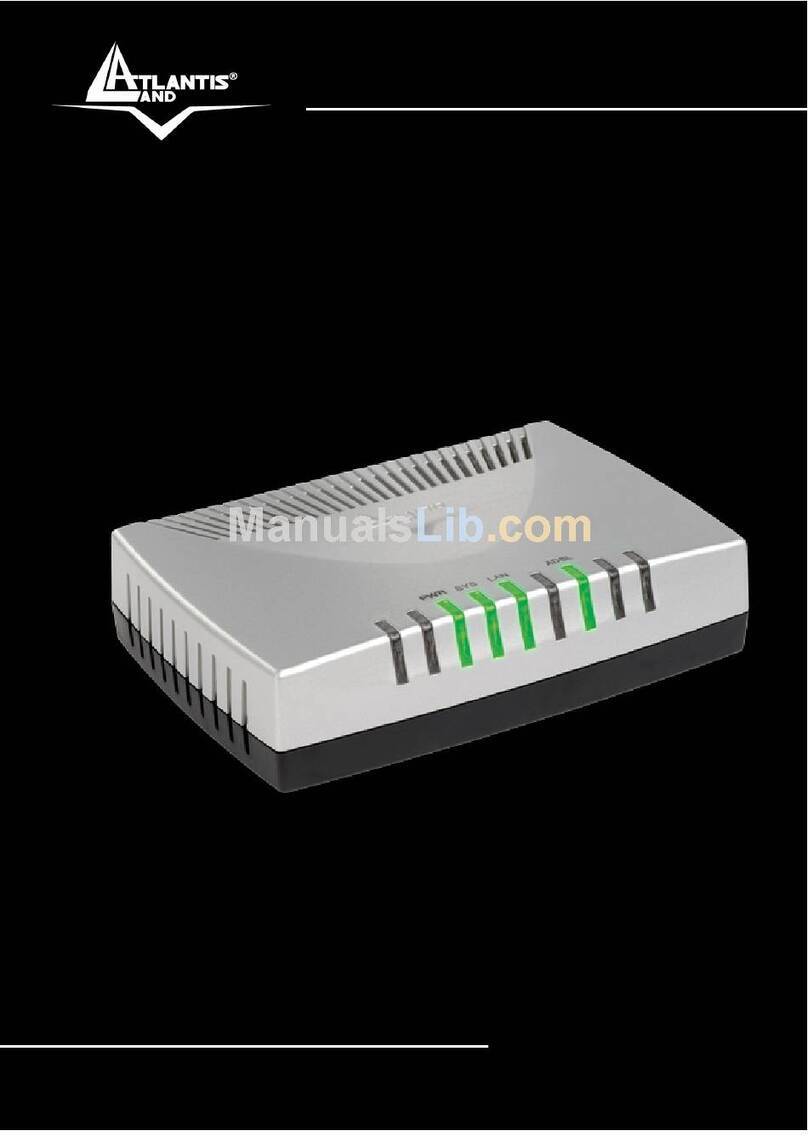
Datalink Systems QBASE 915MHz User manual

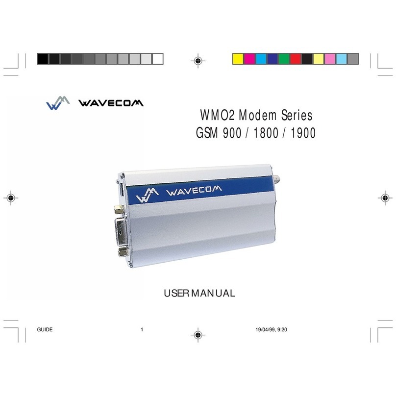
4%$6(0+]'DWDOLQN6\WHP
7KH4%DVH0+]'DWDOLQN6\VWHPFRQVLWVRIWKHIROORZLQJSDUWV
4%DVH$LU0RGHP
$0+]WUDQVFHLYHU0RGXOHIRUWKHLQWHJUDWLRQLQDIL[HGZLQJ8$9
4%DVH*URXQG&RQWURO6WDWLRQ
$0+]WUDQVFHLYHU0RGXOHZKLFKKDVWREHFRQQHFWHGWRDODEWRS
4%DVH6RIWZDUH
WRSODQWKH8$9IOLJKWPLVVLRQ
7HFKQLFDO'DWD
2SHUDWLRQIUHTXHQF\ 0+]
0RGXODWLRQFKDQQHOV *)6.)+66
2XWSXW3RZHU G%P(,53
$QWHQQD$LU0RGHP 60$ZDYHVWXEE\DQWHQQD*DLQG%L
$QWHQQD*URXQG6WDWLRQ60$H[WHUQDOKHOLFDODQWHQQD*DLQG%L
&RQWDLQHG)&&,'$3$%4%$6(IRUOLPLWHGPRGXODUDSSURYDO

QBASE 915MHz Datalink Sytem
FCC Warning Statements
This device complies with part 15 of the FFC rules. Operation is subject to the following two conditions:
(1) This device may not cause harmful interference, and (2) this device must accept any interference received,
including interference that may cause undesired operation.
Note: This equipment has been tested and found to comply with the limits for a Class B digital device,
pursuant to part 15 of the FCC Rules. These limits are designed to provide reasonable protection against
harmful interference in a residential installation. This equipment generates, uses and can radiate radio
frequency energy and, if not installed and used in accordance with the instructions, may cause harmful
interference to radio communications. However, there is no guarantee that interference will not occur in a
particular installation. If this equipment does cause harmful interference to radio or television reception,
which can be determined by turning the equipment off and on, the user is encouraged to try to correct the
interference by one or more of the following measures:
--Reorient or relocate the receiving antenna.
--Increase the separation between the equipment and receiver.
--Connect the equipment into an outlet on a circuit different from that to which the receiver is connected.
--Consult the dealer or an experienced radio/TV technician for help.

12 | Trinity user manual
QBASE – GROUND CONTROL STATION
7
CHAPTER
QBase is a Microsoft Windows based desktop software. QBase assists the user in planning a mission. The planning process is
always accomplished in the following order:
120 m
Wind
APC Snap
CPC Snap + UMC
SPC UMC
Choose your payload
Take-off and landing
5HƓQHLQGLYLGXDOO\
'HƓQHPLVVLRQ
settings
Choose Trinity
17 m/s
$IWHUSODQQLQJDPLVVLRQ4%DVHDVVLVWVWKHXVHULQPRQLWRULQJDQGFRQWUROOLQJWKH7ULQLW\GXULQJWKHŴLJKWEXWDOVRLQGHEULH-
ƓQJWKHPLVVLRQ
Monitoring 'HEULHƓQJ
COME
HOME
EMERGENCY
MISSION
T.BAT
MIS:
BAT:
ALT: 120m
DST: 676m
HDG: 224 °
WP: 4/16
AS: 17.0 m/s
Pics: 112
GS: 17.0 m/s
SATs: 15
49%
90%
06:04
18.5 V
92%
GeoTagging
Find the QBase mission planning video tutorial on our YouTube channel.
Just search for www.youtube.com/c/QuantumSys
tems

Trinity user manual | 13
7QBase – ground control station
7.1 INSTALLING/UNINSTALLING QBASE
The following chapter will deal with the installating and the uninstalling of QBase.
7.1.1 Install QBase
1. QBase is provided by your reseller.
2.2SHQWKH4%DVHLQVWDOOHUƓOHDQGIROORZWKHLQVWUXFWLRQVRIWKHLQVWDOODWLRQJXLGH
3. Open Start QBase to open the program.
Note: For the connection between QBase and the Trinity via the QBase modem a driver is required.
Visit www.ftdichip.com/Drivers/VCP.htm to install the driver.
MINIMUM SYSTEM REQUIREMENTS
OS Windows 7/8.1/10 64bit
CPU-Speed 2.5 GHz or higher (Hyper-threading or Multicore recommended)
RAM 4 GB or higher
Free Disk Space 100 MB
Display 24-bit color depth
Screen Resolution 1600 x 900 recommended or higher at normal size (96 dpi)
Video/Graphic Adapter 64 MB RAM minimum, 256 MB RAM recommended; NVIDIA, AMD, and Intel chipsets supported;
Accelerated graphics card driver; Be sure to use the latest available driver
If you have problems starting QBase, make sure your installation of Microsoft Windows is up to date.
7.1.2 Uninstall QBase
1. Open the QBase installer and select Remove QBase.
2. Select Finish to remove QBase.
Alternative: Uninstall QBase from the program list of the Windows control panel.

14 | Trinity user manual
7.2 MENU OVERVIEW
The graphical user interface of QBase is divided into several sections.
MAP NAVIGATION
The map can be moved by
using left mouse button.
Zooming is possible with the
mouse wheel.
Touch screen devices:
0RYHWKHPDSZLWK RQHƓQ-
JHU8VHWZRƓQJHUVWR]RRP
in and to zoom out.
7.2.1 Main menu (top left corner)
Mission
New
Create a new mission. The current mission will be dele
ted.
Settings
QBase (see chapter 7.10.1)
Open
a mission.
View Manager (see chapter 7.10.2)
Save the current mission in Quantum-Systems
SURSULHWDU\;0/ƓOHIRUPDWXVLQJWKHNQRZQƓOHQDPH Flight Data Link (see chapter 7.10.3)
Save as
6DYHWKHFXUUHQWPLVVLRQZLWKDGLIIHUHQWƓOHQDPH
Create Map
&UHDWHDQRIŴLQHPDSVHHFKDSWHU
Payload
Create Camera (see chapter 7.8)
Maintenance
Updates (see chapter 7.11)
FlyLog Debrief (see chapter 7.7.1) UAV Firmware (see chapter 7.12)
Geo Tagging (see chapter 7.7.2) SD Card (see chapter 7.14)
Exit QBase
7QBase – ground control station

Trinity user manual | 15
7.2.2 Left section
Message Window
Shows info (blue), warning (yellow) and error (red) messages.
Map Settings
Adjust the display settings of the map.
Zoom In Zoom Out
?
Pan to …
Select if you wish to pan to the UAV, to the mission or
if you wish to search for an address.
Select Map
7KHOLVWLQFOXGHVRQOLQHDQGRIŴLQHPDSV7RXVHRQOLQHPDSV
make sure QBase is connected to the internet.
Wind Settings
4%DVHGHWHUPLQHVWKHŴLJKWWUDFNXQGHUFRQVLGHUDWLRQRIWKHZLQGLQŴXHQFH6HHFKDSWHUIRUIXUWKHUGHWDLOV
20 km Zoom in to select the Scale and select New Measurement to measure a distance between two locations.
The button becomes visible when zoomed in. Select the Scale again to close the measurement tool.
7.2.3 Right section
The right section of QBase includes the relevant buttons for planning and monitoring a mission (see chapter 7.3 & 7.6).
Monitoring UAV
Monitor the UAV during the mission accomplishment.
Mission Template
'HƓQHWKHJHQHUDOPLVVLRQVHWWLQJV
Flight Planning
'HƓQHWKHWDNHRIIDQGODQGLQJSRVLWLRQDQGDGMXVWWKH
waypoints.
Area Planning
'HƓQHWKHŴLJKWDUHD
Read / Write Flight Plan
8SORDGWKHŴLJKWSODQWRWKH7ULQLW\VHHFKDSWHU
7.2.4 Footer
UAV Command UAV Command
Enables the user to control the Trinity via QBase (see chapter 7.6.2)
Payload Info Payload Info
Information about the current state of the payload (see chapter 7.6.3.)
$OWLWXGH3URƓOH $OWLWXGH3URƓOH
7KHDOWLWXGHSURƓOHRIWKHFXUUHQWŴLJKWWUDFNFDQEHGLVSOD\HGLQWKHERWWRPFHQWHU
$OWLWXGH3URƓOH1DYLJDWLRQ
•
By clicking left on the $OWLWXGH3URƓOHWKHDOWLWXGHDQGWKHŴLJKWGLVWDQFHLVGLVSOD\HG
•The waypoints of the mission are numbered and shown in purple.
•The current waypoint is framed.
•0RYHWKHSURƓOHZLWKWKHULJKWPRXVHNH\
•Zoom in and out with the mouse wheel.
•Use AutoscaleWRGLVSOD\WKHFRPSOHWHSURƓOH
Mission Info Mission Info
Gives an overview of the planned mission (see chapter 7.3 step 51).
7QBase – ground control station

16 | Trinity user manual
7.3 PLANNING A PHOTOGRAMMETRY MISSION
The aim of planning a mission in QBase is to generate waypoints and camera trigger positions. This information is uploaded
to the Trinity.
Mission planning – step by step
The planning process should be accomplished in the following order. With increasing step order the planning process
becomes more detailed. Settings that are adjusted are not automatically updated in the previous steps. Therefore, it is not
recommended to jump back and forth between the steps. See chapter 7 for an overview of the mission planning process.
%HIRUHSODQQLQJWKHPLVVLRQLWLVUHFRPPHQGHGWRYLVLWWKHŴLJKWDUHDWRJHWDQRYHUYLHZRIWKH
surrounding and the topographic conditions. See chapter 8.4 for choosing a good take-off position.
1. Set the wind condition. Get information of the wind speed and the wind direction online.
Set the wind speed [BFT or m/s]
Set the wind direction:
+ clockwise
- counter clockwise
2. Open the Mission Template in the right section.
UAV
3. Select the UAV type Trinity.
4.
Set the Link Loss conditions.
,IWKH5&OLQNDVZHOODVWKHŴLJKWGDWDOLQNLVORVWORVWGXULQJWKHŴLJKWWKH7ULQLW\UHWXUQVWRWKHOLQNUHHVWDEOLVKLQJZD\SRLQW
after the selected time expired.
5. Set the Loiter Time.
At the link reestablishing waypoint the Trinity loiters for the selected time and tries to reestablish the connection to QBase
and the transmitter. See chapter 5 for further information about the communication links. See step 42 to set the link reesta-
blishing waypoint
General Mission
6. Set the SpeedDLUVSHHG
7RUHFHLYHRSWLPDOSKRWRJUDPPHWU\UHVXOWVWKHŴLJKWVSHHGPXVWEHVHWGHSHQGLQJRQWKHZLQGVSHHG
RECOMMENDED SETTINGS
Wind speed Flight speed
0–3 m/s 17 m/s
3–6 m/s 18 m/s
7. Set the Altitude.
)RUWKH7ULQLW\FDPHUDSD\ORDGSUHVHWVLWLVUHFRPPHQGHGWRVHWWKHŴLJKWDOWLWXGHWRPHWHUVIW Please do not
H[FHHGWKHPD[LPXPDOWLWXGHWKDWLVDOORZHGIRU\RXUUHJLRQ7KHŴLJKWDOWLWXGHLVGHƓQHGDVWKHDOWLWXGHDERYHWKH
take-off position.
8. Set the Side and Forward Overlap.
Overlap settings are dependent on the payload. Overlap default settings in Mission Template are based on the payload
settings.
Payload
9. Select the Payload. Focal length of the camera.
*6'7KHJURXQGVDPSOHGLVWDQFHGLVWDQFHRQWKHJURXQGEHWZHHQWKHPLGRIWZRSL[HOVLVFDOFXODWHGEDVHGRQWKHŴLJKW
altitude and the camera properties.
7QBase – ground control station

Trinity user manual | 17
7ULJJHU6SHHG7KHWULJJHUVSHHGLQWHUYDOEHWZHHQLPDJHVLVFDOFXODWHGEDVHGRQWKHŴLJKWVSHHGŴLJKWDOWLWXGHDQG
forward overlap. The wind speed and the wind direction is not considered at this point. For the exact trigger
speed including the wind conditions see step 51.
If the selected camera can not manage the required trigger speed the trigger speed is displayed in red color.
,QWKLVFDVHWU\WRVZLWFKWKHVLGHDQGIRUZDUGRYHUODSVHWWLQJVRUVHOHFWDKLJKHUŴLJKWDOWLWXGH
10. Either select
Pan to …
?
in the left section and search for the desired location or zoom to the desired location.
11. Open
Area Planning by selecting LQWKHULJKWVHFWLRQ$SD\ORDGPXVWEHGHƓQHGLQWKHMission Template before.
12. Select Create a new area in the header section.
7KHŴLJKWDUHDLVFUHDWHGE\GHƓQLQJWKHFRUQHUVRIWKHDUHD(DFKFOLFNRQWKHPDSJHQHUDWHVDFRUQHURIWKHDUHD7KH
DUHDLVGLVSOD\HGDIWHUGHƓQLQJWKUHHFRUQHUV7KHRUDQJHKLJKOLJKWHGFLUFOHUHSUHVHQWVWKHVHOHFWHGFRUQHU7RPRYHD
corner it must be selected.
Undo Redo Cancel
Delete selected vertex (orange circle)
13. :KHQWKHŴLJKWDUHDLVGHƓQHGselect
.
14. If you wish to edit the ŴLJKWDUHD select
.
15. If you wish to deleteWKHŴLJKWDUHDVHOHFW
.
16. Select Mission Info
t
o display the size of the planned area.
Note:,QIRUPDWLRQDERXWWKHŴLJKWSDWKDQGPLVVLRQSD\ORDGDUHQRWDYDLODEOHDWWKLVSODQQLQJVWDWH
7KHOHJVDUHQXPEHUHGDQGGLVSOD\HGZLWKLQWKHŴLJKWDUHD7KHƓUVWZD\SRLQWRIWKHŴLJKWDUHDLVLQGLFDWHG
by a green colored triangle S.
17. Adjust theŴLJKWDOWLWXGH
18. Set the direction of the the legs. Set the direction to Auto to obtain the minimum
amount of legs. Set the direction to Manual if it is useful to change the legs depen-
ding on the wind direction.
19. Set the distance between the legs.
Percent: distance based on side overlap in percent
Manual: distance between the legs
Gap: set the gap between the legs
,QLWLDOVHWJDSEHWZHHQWKHƓUVWOHJDQGWKHŴLJKWDUHDERUGHU
20. Legs can be extended DWWKHHQWU\DQGWKHH[LWRIWKHŴLJKWDUHD%\GHIDXOWWKH
legs at the entry are extended by 10 meters.
21. Check Flip Legs to change the waypoint orderRIWKHFRPSOHWHŴLJKWSODQ
22. Check Invert Legs to change the entry and exit on a leg.
23. Check Optimize Leg Sequence to optimize the leg order based on turn radius of
the Trinity and the current leg distance.
24. Select Generate Flight Plan.
Note: If changes in Area Planning or Mission Template are made afterwards, the
ŴLJKWSODQKDVWREHXSGDWHGE\VHOHFWLQJGenerate Flight Plan again.
The number of waypoints is limited to 200. If the amount is exceeded, the button is disabled.
25. The Flight Planning menu RSHQVDQGWKHZD\SRLQWVDUHGLVSOD\HGZLWKLQWKHŴLJKWDUHD
26. Waypoints can be edited, added and deleted in the header section.
View Settings
Area: Shows the area including the numbered legs.
)OLJKWSODQ 6KRZVWKHŴLJKWWUDFNZLWKRXWFRQVLGHUDWLRQRIWKHZLQGDQGŴLJKWG\QDPLFV
6LPXODWHGSDWK &RQVLGHUVWKHZLQGGLUHFWLRQDQGŴLJKWG\QDPLFVDQGLVWKHUHIRUHPRUHUHDOLVWLFWKDQWKHJUHHQ
GLVSOD\HGŴLJKWSODQ
Highlighted path: Highlights the simulated path between the previous, the current and the next waypoint.
Trigger positions: Displays the trigger positions (yellow dots).
Waypoints: Shows the waypoints.
7QBase – ground control station

18 | Trinity user manual
Lock/ Unlock Waypoint Moving
Enables/ Disables the function to move any waypoint. Waypoints can be moved by selecting and dragging them.
Set New Waypoints
By selecting on the map a new waypoint between two existing waypoints can be added.
Delete Waypoints
When selected choose the waypoints that you wish to delete.
Delete Flight Plan
27.
Set the Home Waypoint by selecting in the header section.
'HƓQHWKHSODQQHGWDNHRIIDQGODQGLQJSRVLWLRQ7KHUHDOWDNHRIISRVLWLRQLVDXWRPDWLFDOO\DGMXVWHGULJKWEHIRUHWKHVWDUW
RIWKHŴLJKWVHHFKDSWHUVWHS
The yellow part indicates the transition cone with the transition track which is by default 50 meters.
Within this area the transition is performed. Make sure this area is free of obstacles. To adjust the
direction and the angle of the transition cone see step 31.
28. Select the Home Waypoint on the map in order to set the transition waypoint properties.
Direction
31
A: Transition altitude (m)
B:$OWLWXGHRIWKHƓUVWZD\SRLQW
C: Time between home waypoint
DQGƓUVWZD\SRLQWPPVV
D: Track length between the home
ZD\SRLQWDQGWKHƓUVWZD\SRLQWP
29. Set the Transition Altitude.
If the surrounding allows for it, set the transition altitude as low as possible in order to save energy by reducing the hover
duration to a minimum.
30. Set the direction of the transition.
Note: Choose the transition direction based on the surrounding. If possible set it against the wind direction.
31. Set the Transition Cone.
7KHWUDQVLWLRQLVSHUIRUPHGZLWKLQWKHGHƓQHGFRQH$VORQJDVWKHGLUHFWLRQRIWKH7ULQLW\GRHVQRWPDWFKWKHFRQHWKH
Trinity will not enter the transition phase and the mission will be aborted. It is possible to manually adjust the direction of
the Trinity (see chapter 9.2).
32. Open the $OWLWXGH3URƓOHDQGHQVXUHWKDWWKHGLVWDQFHEHWZHHQWKHKRPHZD\SRLQWDQGWKHƓUVWZD\SRLQWRIWKHŴLJKW
DUHDLVVXIƓFLHQWWRUHDFKWKHUHTXLUHGŴLJKWDOWLWXGH)RUDOWLWXGHSURƓOHQDYLJDWLRQVHHFKDSWHU
$OWLWXGH3URƓOH
0 0,5
12 0
H
123
&
50
$OWLWXGH3URƓOH
0 0,5
12 0
123
'
50
H
)OLJKWDOWLWXGHLVUHDFKHGDWWKHƓUVWZD\SRLQWRIWKHŴLJKWDUHD)OLJKWDOWLWXGHLV127UHDFKHGDWWKHƓUVWZD\SRLQWRIWKHŴLJKWDUHD
33. If the altitude can not be reached
• try to flip or invert the legs (see step 21 – 23) or
• extend the track between the home waypoint and the first waypoint of the flight area by inserting extra waypoints in
between (see step 26).
Remember to update the flight plan by selecting Generate Flight Plan.
7QBase – ground control station

Trinity user manual | 19
$OWLWXGH3URƓOH
0 0,5
50
12 0
123
Distance: 0,4
Altitude: 75
H
,IREVWDFOHVDUHLQWKHŴLJKWWUDFN during climbing
phase
EHWZHHQWKHWUDQVLWLRQDQGWKHƓUVWZD\SRLQW
HQVXUHWKDWWKHŴLJKWDOWLWXGHLVKLJKHUWKDQWKH
obstacles are. Add a waypoint at the obstacle.
&KHFNWKHŴLJKWDOWLWXGHIRUWKLVSRVLWLRQLQWKH
DOWLWXGHSURƓOH
35. Set the Retransition Waypoint by selecting in the header section.
Location at which the Trinity finishes the retransition and is in hover mode short before
landing. The retransition track is indicated by the dotted pa
th and is by default 150 meters.
The retransition track must be free of any obstacles.
The retransition waypoint should be located close to the home waypoint
(take-off and landing location), because the distance between the
retransition waypoint and the home waypoint is covered in high energy
demanding hover mode.
7KHŴLJKWWUDFNEHWZHHQWKHUHWUDQVLWLRQZD\SRLQWDQGWKHKRPHZD\SRLQWPXVWEHIUHHRIREVWDFOHV'HSHQGLQJRQWKHZLQG
condition real retransition location might not comply with the retransition waypoint in QBase. Therefore, make sure an area
with a radius of 20 meters around the retransition waypoint is free of obstacles.
36. Select the retransition waypoint on the map in order to set the retransition properties: Distance between the retransi-
tion point and the home waypoint. The distance is covered in hover mode. At the home waypoint the Trinity is landed
manually (see chapter 9.2).
40
37.
Set the
retransition altitude.
'HƓQHVWKHKRYHUDOWLWXGHDWWKHHQGRIWKHUHWUDQVLWLRQ
,IWKHŴLJKWDUHDDOORZV
for it, set the retransition altitude as low as possible in order to save energy by
reducing the hover duration to a minimum.
38. Set the speed
RIWKHUHWUDQVLWLRQ7KHŴLJKWWUDFNEHWZHHQWKHODVWZD\SRLQWDQG
WKHEHJLQQLQJRIWKHUHWUDQVLWLRQLVFRYHUHGZLWKWKHGHƓQHGVSHHG
39. Set the direction of the retransition. If possible set the direction against the wind
direction.
40. Set the direction of the descent circle.
Before the retransition, the Trinity enters the descent circle automatically in order
to descend to the required retransition altitude. In case no link reestablishing
waypoint is set the Trinity will use the descent circle as the link reestablishing
waypoint. Set the direction of the circle depending on the surrounding and
obstacles.
Make sure the descent circle is free of obstacles.
,IREVWDFOHVDUHLQWKHŴLJKWWUDFN between the last waypoint and the descent circle ensure that the
ŴLJKWDOWLWXGHLVKLJKHUWKDQWKHREVWDFOHVDUHE\FKHFNLQJWKHDOWLWXGHSURƓOH$GGDZD\SRLQWDWWKH
REVWDFOH&KHFNWKHŴLJKWDOWLWXGHIRUWKLVSRVLWLRQLQWKHDOWLWXGHSURƓOH
43
44
45
46
42. Locate the Link Reestablishing Waypoint by selecting in the header section.
$IWHUOLQNORVVWLPHRXWWKH7ULQLW\UHWXUQVDQGFLUFOHVDURXQGWKHGHƓQHGZD\SRLQW,I
it is possible the link between QBase and the Trinity or between the RC transmitter
and the Trinity is reestablished. If the connection is successful either continue the
mission or select COMING HOME on the transmitter. Locate the Link Reestablishing
:D\SRLQW close to the home waypoint.
43. Set the altitude of the link reestablishing circle.
44. Set the ŴLJKWVSHHGof the link reestablishing circle.
45. Set the radius of the link reestablishing circle.
46. Set the direction of the link reestablishing circle.
7QBase – ground control station

20 | Trinity user manual
48
49
50
47. If needed adjust the waypoints.
It is possible to adjust the settings for every waypoint individually.
Select the waypoint that you wish to modify.
48. Select the waypoint type. By default, the waypoint type is selected
WRPHHWWKHUHTXLUHPHQWVWRPDSWKHŴLJKWDUHDSURSHUO\
49. Set theŴLJKWDOWLWXGH at the selected waypoint.
50. Set theŴLJKWVSHHG at the selected waypoint.
Waypoint types
The selected waypoint is displayed in green.
Fly By
7KHZD\SRLQWLVQRWGLUHFWO\RYHUŴRZQEXWWKH7ULQLW\WXUQV
before reaching the waypoint to smoothly align with the next
leg.
Fly Over
7KHZD\SRLQWLVGLUHFWO\RYHUŴRZQ7KH7ULQLW\UHDOLJQVZLWK
the next leg after the waypoint.
Aligned Direction
7KHŴLJKWWUDFNLVDXWRPDWLFDOO\GHWHUPLQHGLQRUGHUWRPDWFK
the waypoint and the direction of the next leg.
If needed subtypes can be selected in the waypoint property
menu manually. For photogrammetry missions it is recom-
mended to set the subtype to Auto. Not all subtypes are
applicable for every scenario. Non applicable subtypes are
indicated by a red dotted line between the waypoints.
Loiter
The Trinity enters a circular trajectory around the waypoint.
The radius of the trajectory, the circling duration and the
circling direction can be set in the waypoint property menu.
The Trinity approaches and leaves the trajectory from the
outside.
51. Mission Info
Open the Mission Info menu in the bottom right corner, to obtain an overview of the planned mission.
If the selected camera can not manage the required trigger speed the trigger speed is displayed in red color.
In this case try to switch the side and forward overlap settings in the Mission Template (step 8).
2WKHURSWLRQVDUHVHOHFWLQJDKLJKHUŴLJKWDOWLWXGHRUFKDQJLQJWKHGLUHFWLRQRIWKHOHJVFURVVZLQG
52. Select $OWLWXGH3URƓOH LI\RXZLVKWRREWDLQDQRYHUYLHZRIWKHDOWLWXGHSURƓOH
7QBase – ground control station

Trinity user manual | 21
7.4 UPLOADING A FLIGHT PLAN TO THE TRINITY
,I4%DVHLVVXFFHVVIXOO\FRQQHFWHGWRWKH7ULQLW\YLDWKH4%DVHPRGHPWKHŴLJKWSODQFDQEHWUDQVIHUUHGWRWKH7ULQLW\7KHŴLJKW
SODQWKDWLVVDYHGRQWKH7ULQLW\LVOLPLWHGWRWKHUHOHYDQWLQIRUPDWLRQQHFHVVDU\IRUWKHŴLJKWRSHUDWLRQDQGGRHVQRWLQFOXGH
information of the mission template and the area planning.
1. Select in the right section.
2. Select Write Flight Plan
Write
Flight Plan
.
3. The following Flight Plan Check JLYHVDQRYHUYLHZLIHYHU\FULWHULDWRXSORDGWKHŴLJKWSODQLVPHW
A: UAV Type Check
,WLVQRWSRVVLEOHWRZULWHDŴLJKWSODQWRWKH7ULQLW\WKDWZDVSODQQHGIRU7URQ
B: Distance Retransition to Home
The user is warned if the distance between the home waypoint and the retran-
sition waypoint exceeds 50 meters. If the distance exceeds 100 meters it is not
SRVVLEOHWRZULWHWKHŴLJKWSODQWRWKH7ULQLW\
C: Predicted Battery Usage
A warning comes active if the required battery capacity exceeds 75%.
D: Trigger Interval
The required payload trigger interval should not be shorter than the minimum
WULJJHULQWHUYDORIWKHFDPHUD,IDFRQŴLFWRFFXUVSOHDVHVHHFKDSWHUVWHS
,WLVQRWUHFRPPHQGHGWRZULWHWKHŴLJKWSODQLIDFRQŴLFWRFFXUV
4. Select Write Flight Plan. The button is disabled if one of the criteria is not met. The window is closed automatically after
VHFRQGV,IWKHŴLJKWSODQFDQQRWEHZULWWHQWRWKH7ULQLW\PDNHVXUH4%DVHLVFRQQHFWHGFRUUHFWO\
Note:,WLVQRWSRVVLEOHWRVDYHPRUHWKDQRQHŴLJKWSODQRQERDUGRIWKH7ULQLW\
)RUVWHSE\VWHSŴLJKWVHWXSLQFOXGLQJXSORDGLQJWKHŴLJKWSODQWRWKH7ULQLW\VHHFKDSWHU
7.5 DOWNLOADING A FLIGHT PLAN FROM THE TRINITY
,IWKH7ULQLW\LVFRQQHFWHGWR4%DVHYLDWKH4%DVHPRGHPLWLVDOVRSRVVLEOHWRUHDGDŴLJKW3ODQIURPWKH7ULQLW\7KHPLVVLRQ
is transferred from the Trinity to QBase. The current QBase mission is overwritten.
Note:7KHŴLJKWSODQGRHVQRWLQFOXGHLQIRUPDWLRQRIWKHPLVVLRQWHPSODWHDQGWKHDUHDSODQQLQJ
7.6 MONITORING AND CONTROLLING THE TRINITY DURING FLIGHT OPERATION
With QBase it is possible to monitor and to control the Trinity during a mission. When the Trinity is connected to QBase via the
QBase modem the actual position of the Trinity is shown on the map
. To connect QBase with the Trinity see chapter 8.3
& 8.7.
Monitoring UAV
The current status of the Trinity can be seen in the header section. UAV status messages and error messages are dis-
played on the left.
UAV Command
The UAV Command panel provides the user with the possibility to control the Trinity during a waypoint
based mission.
Payload Info During the mission the current state of the payload board can be displayed by selecting Payload Info in
the footer section.
7QBase – ground control station

22 | Trinity user manual
7.6.2 UAV command
During the mission the Trinity can be controlled with the help of the UAV Command panel. As no control sticks are available
WKHIXQFWLRQLVOLPLWHGWRDXWRPDWLFZD\SRLQWŴLJKWPRGH,WLVQRWSRVVLEOHWRŴ\PDQXDOO\LQDVVLVWHGŴLJKW
Open the
UAV Command
panel in the footer section. The control commands are equivalent to the commands on the transmitter.
13
1. Battery state of your tablet or laptop
2. Number of satellites
3. Status of the FDL connection
4. Remaining mission time
5. Battery state of the Trinity
6. Number of the taken pictures
7. Current altitude above take-off
8. Distance to the Home Waypoint
9. Heading (direction of the nose of the Trinity)
10. Waypoints (current/overall)
11. Current airspeed
12. Current ground speed
13. Flight operation commands (see chapter 9.2)
7.6.3 Payload info
Payload Info The 3D\ORDG,QIR interface provides the user with information about the state of the power supply of the
SD\ORDGGXULQJWKHŴLJKW,ISUREOHPVRFFXUWKHGDWDLVGLVSOD\HGLQUHG3OHDVHFRQWDFW\RXUUHVHOOHU
7QBase – ground control station
7.6.1 Header section
1: Sensor data shows the current state of the sensors.
green: OK
red: sensor error
2: Current airspeed
green: deviation between current and commanded
airspeed <10%
orange: deviation between current and commanded
airspeed 10% – 20 %
red: deviation between current and commanded
airspeed >20 %
3: Commanded airspeed
4: Current ground speed
5: Current altitude
green: deviation between current and commanded
airspeed <10%
orange:
deviation between current and commanded
airspeed 10% – 20 %
red: deviation between current and commanded
airspeed >20%

Trinity user manual | 23
7.7 DEBRIEFING OF A PHOTOGRAMMETRY MISSION
'RZQORDGWKH)O\/RJLQFOXGLQJ.0/DQGWDJJLQJƓOHV
)O\/RJVDUHJHQHUDWHGGXULQJWKHŴLJKWDQGVDYHGRQWKHDXWRSLORWERDUGRI
the Trinity. With the help of QBase it is possible to transfer the FlyLog from
the Trinity to your computer, laptop or tablet.
Moreover QBase offers the opportunity to create a KML (Keyhole Markup
/DQJXDJHƓOHDQGDWDJJLQJƓOHIURPWKH)O\/RJ:LWKWKHKHOSRI.0/ƓOHV
WKHSRVVLELOLW\LVSURYLGHGWRGLVSOD\WKHŴLJKWSDWKLQDQ(DUWKEURZVHUOLNH
Google Maps or Google Earth. Download the FlyLogs to geotag the pictu-
res with the geodata (see chapter 7.7.2).
1. Connect the Trinity main body to your computer via USB. Do not
connect the battery. The power is supplied by the USB connection.
2. Open the QBase Main Menu and select FlyLog Debrief .
3. Show the list of Logs by selecting
.
4. 6HOHFWLI\RXZLVKWRGRZQORDGWKH)O\/RJRQO\RULI\RXZRXOGDOVROLNHWRKDYHWKH.0/DQGWKHWDJJLQJƓOH
generated from the FlyLog.
5. Select the ORJƓOH that you wish to download from the Trinity and select 'RZQORDG.
6. Choose a directory.
7. By selecting Load from FolderLWLVDOVRSRVVLEOHWRFUHDWHD.0/ƓOHDQGDWDJJLQJƓOHIURPD)O\/RJWKDWLVVDYHGRQ
your computer.
7.7.2 Geotag the pictures with the geodata
QBase offers the possibility to geotag the pictures that were taken during the mission with geodata. This enables the user
to post-process the pictures with the help of a photogrammetry software. The pictures are saved on a SD card which is on
board of the Trinity.
1. Download the FlyLog from your Trinity (see chapter 7.7.1).
2. Remove the SD card from the payload compartment.
3. Insert the SD card into your computer, laptop or tablet.
4. Save the pictures on your computer, laptop or tablet.
5. Open the Main Menu in QBase and select Geo Tagging .
6.
Select the FlyLogELQ
7.
Select
the camera that the pictures were taken with.
7QBase – ground control station
6: Commanded altitude
7: Remaining battery capacity in percent
8: Remaining mission time
9: Payload
The connection status of the cameras as well as the
number of pictures are displayed.
Count: amount of pictures/ amount of trigger attempts
10: State of the connection between QBase and the Trinity
(green graph)
11: RSSI – state of the received data (yellow graph)
QRŴLJKWGDWDOLQNFRQQHFWLRQ

24 | Trinity user manual
8.
Select
the folder that contains the pictures.
9.
Select
Start.
10
.The geotagged pictures are saved in the folder GeoTagged, a subfolder of the folder that contains the original pictures.
After saving the pictures on your computer, laptop or tablet it is recommended to delete the pictures from the SD card.
7.8 PAYLOAD
%DVHGRQWKHWKUHHVWDQGDUGSD\ORDGFRQƓJXUDWLRQVWKUHHSD\ORDGVDUHSUHVHWLQ4%DVH3OHDVHVHHFKDSWHUIRUWKH
WKUHHVWDQGDUGSD\ORDGFRQƓJXUDWLRQV
Creating a new camera
1. Select the Main Menu in the top left corner.
2. Select Create Camera .
3.
Select a camera name.
4. Set camera settings.
The settings need to be obtained from the technical
VSHFLƓFDWLRQVRIWKHFDPHUD
5. Set default forward overlap.
6. Set default side overlap.
7. Set fastest trigger interval.
8. Select to add the camera to the payload list.
9. If you wish to add another camera to the same payload
repeat steps 3.–8.
10. Save the payload in the directory that is selected in settings (see chapter 7.10.1). The payload is automatically added to
the payload list in the Mission Template if it is saved in the payload directory that was selected in the QBase settings.
7.9 CREATING AN OFFLINE MAP
4%DVHRIIHUVWKHRSSRUWXQLW\WRZRUNZLWKRIŴLQHPDSVLQFDVH4%DVHLVQRWFRQQHFWHGWRWKHLQWHUQHW2IŴLQHPDSVFDQEH
FUHDWHGIURPDVHOHFWHGDUHD2IŴLQHPDSVDUHJHQHUDWHGEDVHGRQWKHLQIRUPDWLRQRIWKHRQOLQHPDSV'XULQJWKHFUHDWLRQ
process QBase needs to be connected to the internet.
Note:7KHODUJHUWKHVHOHFWHGDUHDRIDQRIŴLQHPDSLVWKHORQJHULWWDNHVWRJHQHUDWHLW
1.
Select the Main Menu in the top left corner.
2. Select Create Map .
3. Select Load Map.
4.6HOHFWDQDUHDWKDW\RXZLVKWRFUHDWHWKHRIŴLQHPDSRI7KHRIŴLQHPDSLVFUHDWHGRIWKHFXUUHQWO\GLVSOD\HGDUHD
5. Choose the level of detail.
6. Select Estimate Cache SizeWRFDOFXODWHWKHVL]HRIWKHRIŴLQHPDS
7. Select Export Tiles to create the map. The map is saved in the maps directory that is set in QBase settings (see chap-
WHU'HSHQGLQJRQWKHVL]HRIWKHƓOHLWPLJKWWDNHVRPHWLPHWRFUHDWHWKHRIŴLQHPDS
7.10 SETTINGS
7.10.1 Directory settings
:LWKWKHKHOSRIWKLVPHQXWKHGLUHFWRU\RIWKHRIŴLQHPDSVWKHXSGDWHVWKHPLVVLRQVDQGWKHSD\ORDGFDQEHVHW
1. Select the Main Menu in the top left corner.
2. Select QBase .
3.
Select Set Path to change the directories. The new path is automatically saved when the QBase User Interface is closed.
Click to set directory to the default settings.
7QBase – ground control station

Trinity user manual | 25
7.10.2 View manager
:LWKWKHKHOSRIWKHYLHZPDQDJHULWLVSRVVLEOHWRGHƓQHZKLFKFRPSRQHQWVDUHGLVSOD\HGDWZKLFKSODQQLQJRUPRQLWRULQJVWHS
1. Select the Main Menu in the top left corner.
2. Select View Manager .
7.10.3 Flight data link
The frequency band and the transmission power of the QBase modem and of the Trinity modem can be changed. In order to
guarantee a connection between the Trinity and the QBase modem the frequency bands need to match. Normally no changes
QHHGWREHPDGHH[FHSWLI\RXZLVKWRŴ\ZLWKWZR7ULQLW\VVHHFKDSWHU
1.
Connect the QBase modem to your computer, laptop or tablet via USB.
If you wish to change the settings of the Trinity modem
1a. Connect the battery pack to the main body of the Trinity and power the Trinity.
1b. (QVXUHWKDWWKH7ULQLW\LVFRQQHFWHGWR4%DVHYLDWKHŴLJKWGDWDOLQN
2.
Select the Main Menu in the top left corner.
3. Select Flight Data Link.
A
B
C
D
E
A:
Current settings of the Local (QBase) and Remote (Trinity) modem.
0RGHPFRQƓJXUDWLRQ
Changing the frequency band or the transmission power of your Trinity
includes automatically changing the settings of the QBase modem.
B:
Select the modem. The currently selected modem is displayed
(Local or Local & Remote ).
C:
Select the Band.
D:
Select the transmission power.
The transmission power of the QBase modem can be adjusted in a range
of 1.3 mW – 100mW. Please follow the local regulations for the maximum
allowed transmission power.
E:
Select &RQƓJXUH to save the settings.
Note: You can only change the frequency band or the transmission power of your Trinity if the local and remote modems are
connected. Please ensure that only one Trinity and one QBase modem are active when changing the frequency band.
Special case: The frequency band of your Trinity is set to A and the frequency band of the QBase modem is set to B and you
wish to change the frequency bands to B. First change the band of the QBase (local) modem to A in order to
change both frequency bands to B afterwards.
7.11 UPDATING QBASE
If new QBase updates are available a information window informs you when you start QBase. It is recommended to down-
load the new update as soon as it is available.
1. Select the Main Menu in the top left corner.
2. Select Updates
.
3. Select DownloadWRVWDUWGRZQORDGLQJWKHXSGDWH7KHXSGDWHFRQVLVWVRIDQLQVWDOOHUƓOH
4. Close QBase.
5.
Reinstall QBase
with the downloaded installer (see chapter 7.1). The old version of QBase is automatically overwritten.
7QBase – ground control station

26 | Trinity user manual
7.12 UPDATING THE TRINITY
:KHQDQHZ7ULQLW\ƓUPZDUHEHFRPHVDYDLODEOHWKHXVHULVLQIRUPHGYLD4%DVH7KH7ULQLW\ƓUPZDUHXSGDWHLVLQFOXGHGLQD
new QBase update.
1. Follow the steps for downloading and installing a new QBase update (see chapter 7.11).
2. Connect main body of the Trinity with your computer, laptop or tablet via USB (see chapter 7.7.1). Do not connect
the battery. The power supply is guaranteed by the USB connection.
3. Select the Main Menu in the top left corner.
4. Select Update Firmware.
5.
6HOHFWWKHGRZQORDGHGTVƓOHLQWKHQBase 8$9)LUPZDUH 7ULQLW\GLUHFWRU\
6. Follow the instructions of the update guide.
,WLVLPSRUWDQWWRDOZD\VXSGDWH4%DVHDVZHOODVWKH7ULQLW\ƓUPZDUHDVVRRQDVXSGDWHVEHFRPHDYDLODEOH7KHKLJKHVWOHYHO
RIŴLJKWVDIHW\FDQRQO\EHDFKLHYHGZLWKWKHODWHVWVRIWZDUHUHOHDVH7KHUHIRUH4XDQWXP6\VWHPVFDQRQO\RIIHUZDUUDQW\LI
the Trinity and QBase are updated as soon as an update becomes available.
7.13 ERROR MESSAGES AND USER NOTIFICATIONS DISPLAYED IN QBASE
QBase is equipped with two message windows. Please see chapter 14.7 for the messages.
1. Message Window (in the left section)
2. 8VHU1RWLƓFDWLRQV (in the header section)
The user is informed about the current state of the Trinity.
7.14 DOWNLOADING A LOG FILE FROM THE AUTOPILOT SD CARD
7KHORJƓOHLQFOXGHVDOOGDWDRIWKHŴLJKWDQGPLJKWEHQHHGHGE\\RXUUHVHOOHUIRUWURXEOHVKRRWLQJ,QRUGHUWRGRZQORDGWKH
ORJƓOHIROORZWKHVWHSV
1. Select the Main Menu in the top left corner.
2. Select SD Card .
3. Select the latest ORJELQƓOHLQWKHORJVGLUHFWRU\
4.6DYHWKHORJƓOHRQ\RXUFRPSXWHU
7QBase – ground control station
Table of contents
