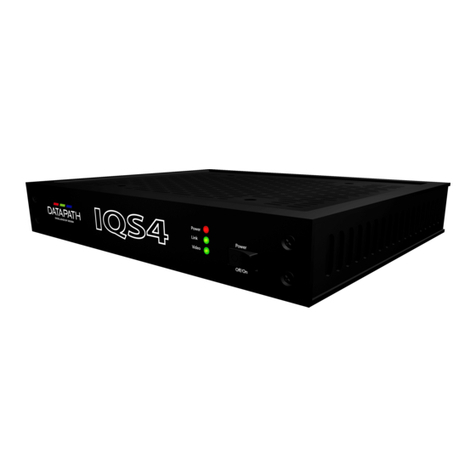
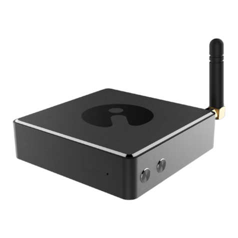
Datapath ALIGO QTX100 User manual

Engineering the world’s best visual solutions
Quick Start Guide
Aligo QTX100
Aligo RX100
Connection

Thank you for purchasing the Datapath
Aligo QTX100 or RX100 units. The aim of
this document is to quickly guide you
through the process of initial setup. If any
of the items are missing, please contact
Datapath for further instructions.
OPTIONAL ACCESSORIES
(PURCHASED SEPARATELY)
10GB 850NM SFP+ MODULES
(ORDER CODE - SFPPLUS10)
RACK MOUNT KIT 1U OR 6U
Aligo Rack Mount Kits are available with order
codes RMK01 (1U) and RMK06 (6U) each with
separate assembly instructions.
CONTENTS
1 x Aligo QTX100 unit, or
1 x Aligo RX100 unit
ALIGO QTX100 (TRANSMITTER UNIT)
Mains Power Cable
4 x HDMI locks 2 x 19" cabinet
mounting brackets
ALIGO RX100 (RECEIVER UNIT)
12V DC External Power Supply
4 x HDMI locks 4 x M4 mounting screws
STEP 1 CONNECTING THE ALIGO QTX100 AND RX100
Display Display Display Display
LAN/VLAN
Aligo QT
X100
Source Source Source Source
Aligo RX100
QTX100
RX100
23
Aligo Quick Start GuideAligo Quick Start Guide

Power
Link
Video
Power
O/On
1 2
Media Utility
1G
HDMI Outputs
Audio Out Power
Made
in the
UK
12V DC
RX100
1 (4K) 2 3 4
10G
100-240V
INPUTSUSB
MODEL 220
MADE IN
ENGLAND
1A MAX 50/60Hz 1A FUSE
1 2 3 4
Power
Link
Video
Power
O/On
1 2
Media Utility
1G
HDMI Outputs
Audio Out Power
Made
in the
UK
12V DC
RX100
1 (4K) 2 3 4
10G
100-240V
INPUTSUSB
MODEL 220
MADE IN
ENGLAND
1A MAX 50/60Hz 1A FUSE
1 2 3 4
HOW TO CONNECT THE ALIGO QTX100 AND ALIGO RX100 ALIGO QTX100 REAR PANEL
ALIGO QTX100 FRONT PANEL
Connect the Aligo QTX100 to a mains power supply.
Connect up to four graphic outputs from your video sources to the HDMI input connectors on
the rear of the Aligo QTX100. Note: Where only one input is required, then input 1 must be used
rst before using inputs 2-4. Input 1 must always be connected to a valid HDMI source in order to
function correctly, and you can only use inputs 2, 3 or 4 when using input 1.
Connect SFP+ transceiver modules into the 10Gb SFP+ cages on the front panel of the Aligo
QTX100, then connect an OM3 (minimum) ber cable into each SFP+ module and connect the
other end to the network switch using another SFP+ module at the switch end. We recommend
using the same manufacturer model and grade of SFP+ module at both ends of the link. Note:
An SFP+ module and 10Gb network connection is required for each HDMI channel i.e. if all four
HDMI inputs are used, then all four network connections must be connected.
Ensure that the switch port chosen has been congured to use the same Local Area Network (LAN/
VLAN) as the active Aetria Network Manager server (see Aetria Network Manager Quick Start Guide
for more information).
Now connect an Aligo RX100 into a spare switch port which has also been congured onto the
same LAN/VLAN as the Aligo QTX100 devices and the active Aetria Network Manager server.
Connect the Aligo RX100 using the 10Gb SFP+ port located on the rear panel.
Connect the Aligo RX100 HDMI output ports to the display devices. Note: Where only one output
display is required, then output 1 must be used rst before using outputs 2-4. Output 1 must always
be connected to a valid HDMI sink in order to function correctly, and you can only use outputs 2, 3
or 4 when using output 1.
Repeat as necessary for all Aligo devices required in the system, connecting all endpoints to the
switch, or switches such that they appear on the same Local Area Network.
Where KVM functionality will be required, connect the USB Type-B ports on the Aligo QTX100
into spare USB ports on the source PC’s that you wish to control. For more information on how to
congure OneControl KVM feature please see separate Aetria documentation.
When connecting USB and HDMI ports to the source PC’s for KVM control, care should be taken
to ensure that each USB channel matches its relative video channel in each case. i.e. USB1 should
connect to the same source as HDMI1 video, USB4 to HDMI4 etc.
1 USB Type B connectors - KVM port for connecting to a USB host PC
2 HDMI input connectors - Connect up to four video sources to the Aligo QTX100
3 Mains power switch
4 Mains power connector
5 10Gb SFP+ Networked Video Transmit Ports.
62 x 1Gb RJ45 Ports – for future use
Please speak to Datapath commissioning representative for further details
1 2
5
3
6
4
45
Aligo Quick Start GuideAligo Quick Start Guide

Power
Link
Video
Power
O/On
1 2
Media Utility
1G
HDMI Outputs
Audio Out Power
Made
in the
UK
12V DC
RX100
1 (4K) 2 3 4
10G
100-240V
INPUTSUSB
MODEL 220
MADE IN
ENGLAND
1A MAX 50/60Hz 1A FUSE
1 2 3 4
Power
Link
Video
Power
O/On
1 2
Media Utility
1G
HDMI Outputs
Audio Out Power
Made
in the
UK
12V DC
RX100
1 (4K) 2 3 4
10G
100-240V
INPUTSUSB
MODEL 220
MADE IN
ENGLAND
1A MAX 50/60Hz 1A FUSE
1 2 3 4
LED’S
ALIGO RX100 REAR PANEL
ALIGO QTX100 FRONT PANEL
7 10Gb SFP+ Networked Video Receive Port
8 1Gb RJ45 LAN extension port for connecting to peripheral devices i.e. displays
9 HDMI 2.0 Primary video output port (4K)
10 HDMI 1.2 Secondary video output ports (HD)
11 Audio Out
12 12V DC power connector
13 USB Ports for connecting to HID devices such as keyboard and mouse
14 Power On/O
7 8 9 11 1210
1413
Power
The green power LED indicates that the device is connected to a power supply and is
switched on. Amber power LED means power is available, but board is switched o
(RX100 only).
Link
O - The device is still powering up.
Flashing on/o - Indicates the device has booted correctly (occurs approximately
30 seconds after power on) but it is not currently registered with the active
Aetria Network Manager server.
Solid on - Indicates that the device has booted and the device is currently registered
by the active Aetria Network Manager server.
Video
Flashing on/o - Indicates that no stable video has been received/transmitted since
last power on.
O - Indicates that no stable video is currently being received/transmitted, but video has
previously been received/transmitted on one or more channels since the last power on.
Solid on - Indicates that a stable video source on one or more channels has been locked
onto by the device and transmitted out onto the network (TX) / received from the network
and output to HDMI sink (RX).
10G Ports The Aligo QTX100 and Aligo RX100 have LEDs on the 10G ports to indicate that each
network channel has good stable power.
67
Aligo Quick Start GuideAligo Quick Start Guide

CONFIGURING ALIGO DEVICES WITHIN AETRIA
Check Device Connections and Network Conguration
First, double check all Aligo devices are connected to the network switch and to their respective video sources
and displays as above before proceeding.
Also ensure that all Aligo devices are on the same Local Area Network (LAN/VLAN) as the Aetria Network
Manager server. This will have been pre-congured by Datapath and should be connected, powered up and
running before going any further.
Once all Aligo devices are connected and powered up, you can verify each device is ready to connect by
checking the link LED is ashing (as per the table on page 7), indicating that it is ready and waiting to be
provisioned within Aetria.
Aligo Device Discovery (Provisioning)
On any machine connected to the Aetria Network, open up a web browser and navigate to the Aetria login
page by following the login instructions. Enter user credentials.
Once within the Aetria Command Center, go to the Manage tab, and select Hardware Conguration.
Then click on Provisioning (highlighted right) to discover the new Aligo sources and add them to the system.
Under the All Devices panel, you will nd any new Aligo devices that have been provisioned on the network.
Once a device has been successfully provisioned, the link LED on each device will be in a solid ON state.
From this point on please refer to the Aetria Command Center quick start guide for further details on using
the system.
From within Aetria you can check all devices are communicating properly by checking the serial numbers
against the discovered devices.
You have now successfully added your new devices to the Aetria system.
Selected
device
properties
Detected
devices
89
Aligo Quick Start GuideAligo Quick Start Guide

COPYRIGHT STATEMENT
© Datapath Ltd., England, 2021
Datapath Limited claims copyright on this documentation. No part of this documentation may be reproduced,
released, disclosed, stored in any electronic format, or used in whole or in part for any purpose other than stated
herein without the express permission of Datapath Limited.
Whilst every eort is made to ensure that the information contained in this Quick Start Guide is correct,
Datapath Limited make no representations or warranties with respect to the contents thereof, and do not
accept liability for any errors or omissions.
Datapath reserves the right to change specication without prior notice and cannot assume responsibility
for the use made of the information supplied. All registered trademarks used within this documentation are
acknowledged by Datapath Limited.
Datapath Ltd declares that this product complies with the essential
requirements and other relevant provisions of Directives 2014/30/EU,
2014/35/EU and 2011/65/EU.
A copy of our Declaration of conformity is available on request.
Datapath Limited
Bemrose House
Bemrose Park
Wayzgoose Drive
Derby, DE21 6XQ
UK
A full list of product compliance certications can be found in the product
User Guide on the Documentation Media supplied with the system.
CERTIFICATION
EU – Class A Declaration of Conformity
10 11
Aligo Quick Start GuideAligo Quick Start Guide

Datapath UK and
Corporate Headquarters
Bemrose House, Bemrose Park,
Wayzgoose Drive, Derby,
DE21 6XQ, United Kingdom
+44 (0) 1332 294 441
Datapath North America
2490 General Armistead Avenue,
Suite 102, Norristown,
PA 19403, USA
+1 484 679 1553
www.datapath.co.uk
QSG-ALIGO-EN1-V2.0
Other manuals for ALIGO QTX100
1
This manual suits for next models
2
Table of contents
Other Datapath Media Converter manuals
