HBM SP4M Series User manual

Mounting Instructions | Montageanleitung |
Notice de montage
English Deutsch Français
SP4M

Hottinger Baldwin Messtechnik GmbH
Im Tiefen See 45
D-64239 Darmstadt
Tel. +49 6151 803-0
Fax +49 6151 803-9100
www.hbm.com
Mat.: 7-2001.2447
DVS: A2447-1.1 HBM: public
07.2016
EHottinger Baldwin Messtechnik GmbH.
Subject to modifications.
All product descriptions are for general information only.
They are not to be understood as a guarantee of quality or
durability.
Änderungen vorbehalten.
Alle Angaben beschreiben unsere Produkte in allgemeiner
Form. Sie stellen keine Beschaffenheits- oder Haltbarkeits
garantie dar.
Sous réserve de modifications.
Les caractéristiques indiquées ne décrivent nos produits
que sous une forme générale. Elles n'impliquent aucune
garantie de qualité ou de durablilité.

Mounting Instructions | Montageanleitung |
Notice de montage
English Deutsch Français
SP4M

2A2447-1.1 HBM: public SP4M
English
1 Safety instructions 3........................................
2 Markings used 7............................................
2.1 Symbols on the product 7.....................................
2.2 Markings used in this document 7..............................
3 Mounting and Load application 9............................
4 Electrical connection 10......................................
4.1 Connecting in four‐wire and six‐wire configurations 10.............
4.2 Shortening the cable 11.......................................
4.3 Cable extensions 11..........................................
4.4 Parallel connection (option) 11..................................
4.5 EMC protection 11............................................
5 Specifications 13............................................
6 Dimensions 17..............................................

Safety instructions
SP4M A2447-1.1 HBM: public 3
1 Safety instructions
In cases where a breakage would cause injury to persons
or damage to equipment, the user must take appropriate
safety measures (such as safety devices to protect
against falls, collapses or overloads). For safe and
trouble‐free operation, load cells must not only be cor
rectly transported, stored, sited and mounted but must
also be carefully operated and maintained.
It is essential to comply with the relevant accident pre
vention regulations. In particular you should take into ac
count the limit loads quoted in the specifications.
Appropriate use
Load cells are designed for metrological applications.
Use for any additional purpose shall be deemed to be not
appropriate.
In the interests of safety, load cells should only be oper
ated as described in the Mounting Instructions. It is also
essential to comply with the legal and safety require
ments for the application concerned during use. The
same applies to the use of accessories.
Load cells can be used as machine elements (for con
tainer and silo weighing, for example). In these situa
tions, you must make sure that for greater sensitivity, the
load cells are not constructed with the customary safety
factors found in machine design. Load cells are not
safety elements within the meaning of appropriate use.
The layout of the electronics conditioning the measure
ment signal should be such that measurement signal fail
ure does not cause damage.

Safety instructions
4A2447-1.1 HBM: public SP4M
General dangers of failing to follow the safety
instructions
Load cells are state‐of‐the‐art and reliable. Load cells can
give rise to remaining dangers if they are inappropriately
installed and operated by untrained personnel.
Everyone involved with siting, starting up, maintaining or
repairing a load cell must have read and understood the
Mounting Instructions and in particular the technical
safety instructions.
Remaining dangers
The scope of supply and performance of the load cells
covers only a small area of weighing technology. In addi
tion, equipment planners, installers and operators should
plan, implement and respond to the safety engineering
considerations of the weighing technology in such a way
as to minimize remaining dangers. Prevailing regulations
must be complied with at all times. Reference must be
made to the remaining dangers associated with the
weighing technology.
Ambient conditions
In the context of your application, please note that be
cause of the alloy elements used, the high‐strength alu
minum alloy only has limited corrosion resistance if it
comes into contact with electrolytes or if there are high
and low pH values. With stainless steel single point load
cells, please note that acids and all materials which re
lease ions will also attack all grades of stainless steel and
their welded seams.
Should there be any corrosion, this could cause the load
cell to fail. If this is the case, the operator must take ap
propriate protective measures.

Safety instructions
SP4M A2447-1.1 HBM: public 5
Unauthorized conversions and modifications are
prohibited
Load cells must not be modified from the design or safety
engineering point of view except with our express agree
ment. Any modification shall exclude all liability on our
part for any damage resulting therefrom.
Qualified personnel
Load cells must only be installed by qualified personnel,
strictly in accordance with the specifications in conjunc
tion with the safety requirements and regulations listed
below. It is also essential to observe the appropriate legal
and safety regulations for the application concerned. The
same applies to the use of accessories.
Qualified personnel means persons entrusted with siting,
mounting, starting up and operating the product, who
possess the appropriate qualifications for their function.
Accident prevention
The prevailing accident prevention regulations must be
taken into account, even though the breaking load is well
in excess of the full scale value. Pay particular attention
to the following data from the specifications
Slimit load (EL)
Slimit load at max. Eccentricity
Slimit lateral loading (ELq)
Sbreaking load.
Load cells are precision measuring elements and must
be handled carefully during mounting and transportation.
Knocking or dropping the load cells can damage them.
Suitable retainers must be used during installation and
operation to protect the load cells against overloading.

Safety instructions
6A2447-1.1 HBM: public SP4M
No forces or moments must be directed via the spring
area during mounting.
Explosion‐proof version (option)
SWhen installing this version, it is essential to comply
with the relevant installation regulations.
SThere must be compliance with the installation condi
tions cited in the Declaration of Conformity and/or the
Type Examination Certificate.
SThe connection cable of the explosion‐proof single
point load cells features free ends (cable configuration
see chapter 4.1, page 10).

Markings used
SP4M A2447-1.1 HBM: public 7
2 Markings used
2.1 Symbols on the product
CE mark
The CE mark enables the manufacturer to guarantee that
the product complies with the requirements of the rel
evant EC directives (the declaration of conformity is
available at http://www.hbm.com/HBMdoc).
Statutory waste disposal mark
In accordance with national and local environmental
protection and material recovery and recycling regula
tions, old devices that can no longer be used must be
disposed of separately and not with normal household
garbage.
If you need more information about waste disposal,
please contact your local authorities or the dealer from
whom you purchased the product.
2.2 Markings used in this document
Important instructions for your safety are specifically
identified. It is essential to follow these instructions in
order to prevent accidents and damage to property.
Markings used
8A2447-1.1 HBM: public SP4M
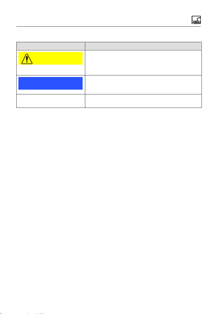
Symbol Significance
CAUTION This marking warns of a potentially dangerous
situation in which failure to comply with safety
requirements can result in slight or moderate physical
injury.
Notice This marking draws your attention to a situation in
which failure to comply with safety requirements can
lead to damage to property.
Emphasis
See….
Italics are used to emphasize and highlight text and
references to other chapters and external documents.
Mounting and Load application
SP4M A2447-1.1 HBM: public 9
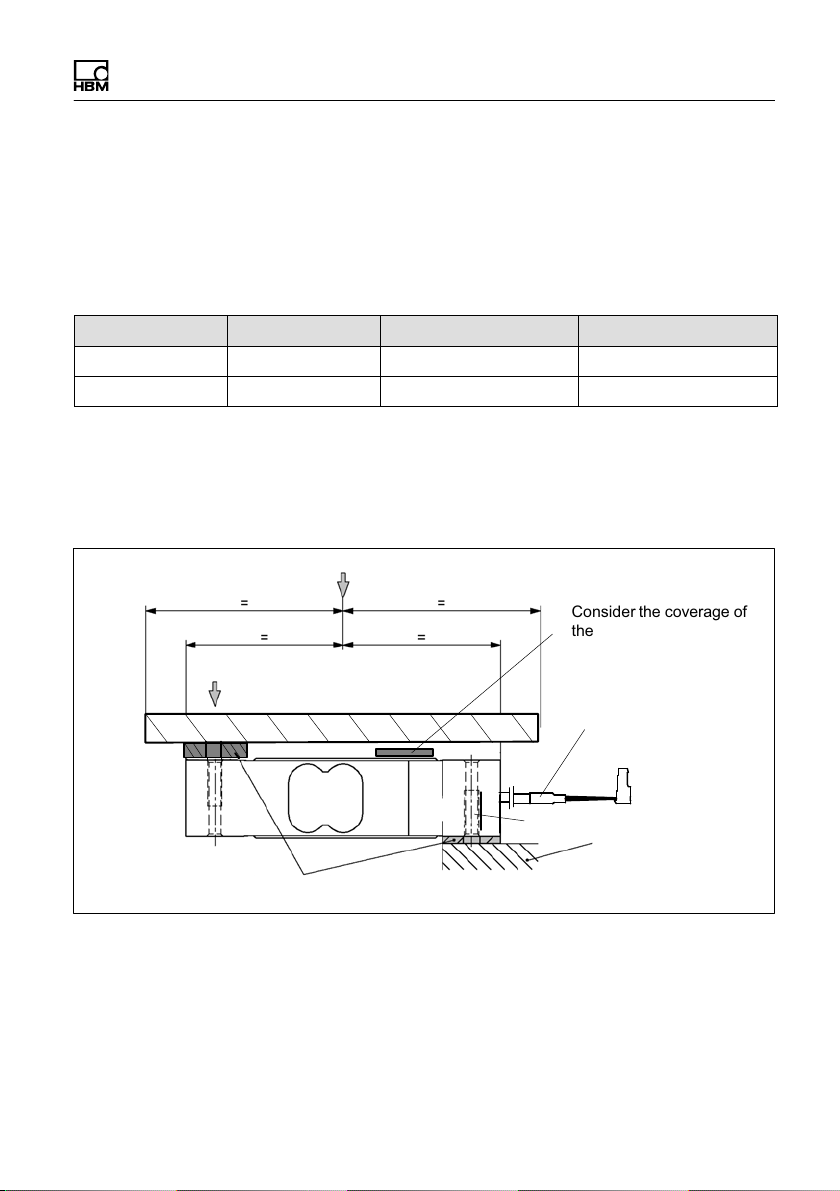
3 Mounting and Load application
The load cells are fixed at the mounting bores. For the
recommended screws and tightening torques refer to the
table below:
Max. capacity Thread Min. property class Tightening torque1)
1...36 kg M6 8.8 6 N@m
50...200 kg M6 10.9 14 N@m
1) Recommendedvalue for the stated property class. For screw dimensioning please refer to the
appropriate information given by the screw manufacturers.
Load must not be applied to the side where the cable
connection is located, as this would cause a force shunt.
ÈÈÈÈÈÈÈÈÈÈÈÈÈÈ
ÈÈÈÈÈÈÈÈÈÈÈÈÈÈ
Consider the coverage of
the ATEX versions (see
chapter 6 “Dimensions”,
page 17)
platform center
load application
connection cable
mounting bores
mounting
spacing washer
Electrical connection
10 A2447-1.1 HBM: public SP4M
4 Electrical connection
The following can be connected for measurement signal
conditioning:
Scarrier‐frequency amplifier
SDC amplifier
designed for strain gage measurement systems.
4.1 Connecting in four‐wire and six‐wire
configurations
When load cells in a six‐wire configuration are connected
to amplifiers with a four‐wire configuration, the sense
leads of the load cells must be connected to the corre
sponding excitation leads.
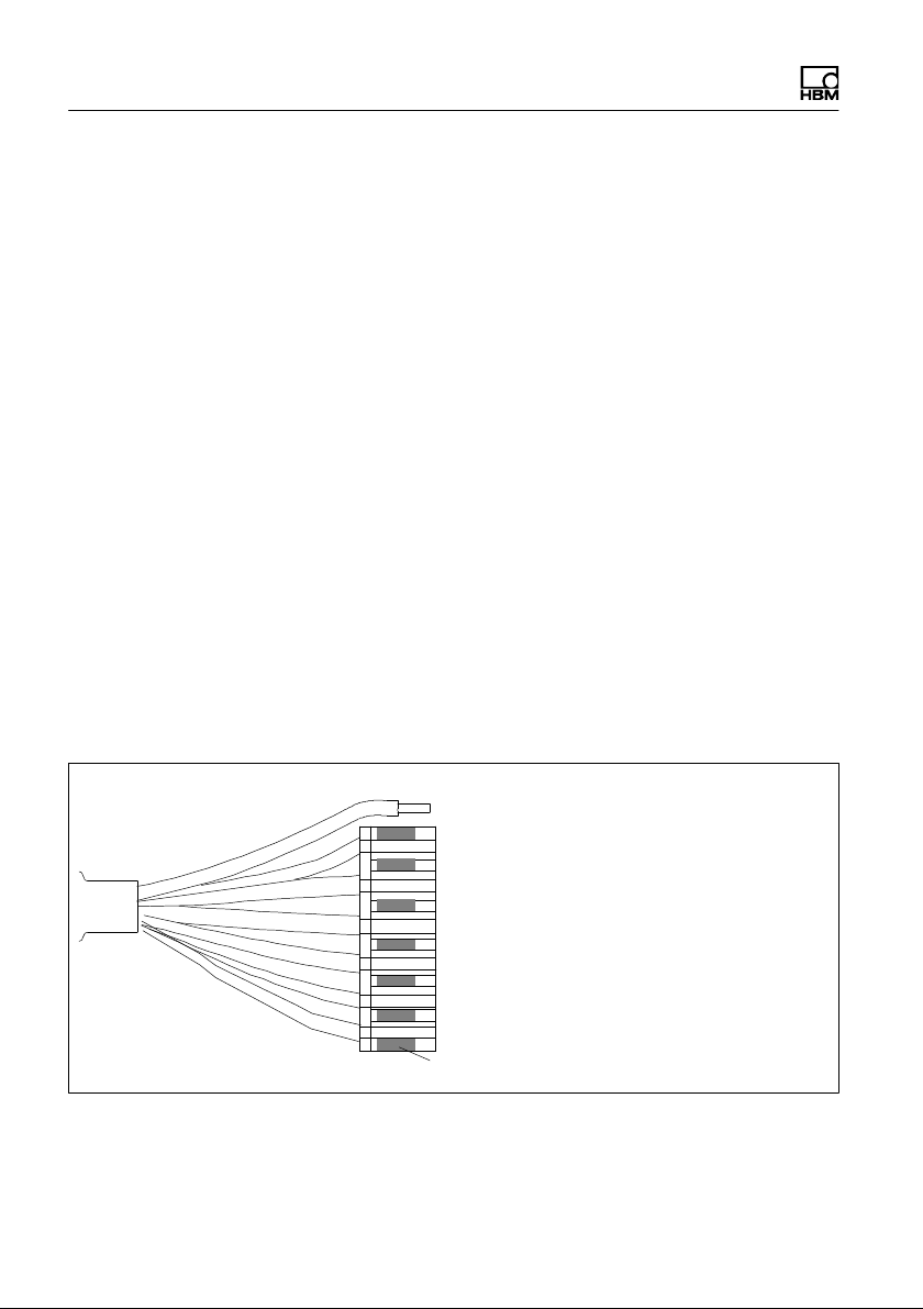
6‐wire cable connection (a choice of lengths: 1.5 m;
3 m; 6 m; 12 m)
4
Contact 1 (white) = Measurement signal (+)
Contact 3 (black) = Excitation (-)
Contact 6 (gray) = Signal (-)
Contact 4 (blue) = Excitation (+)
Contact 5 (green) = Signal (+)
Contact 2 (red) = Measurement signal (-)
12356
blue marking
Shield (yellow) = cable shield connected to
lead cell body
Fig. 4.1 Schematic diagram of a Pancon connector
(CE 100F26-6), 6-pin

Electrical connection
SP4M A2447-1.1 HBM: public 11
4.2 Shortening the cable
When the 6-wire configuration is used, the load cell's
6-wire cable can be cut off without impairing measure
ment accuracy.
4.3 Cable extensions
You must only use shielded, low‐capacitance measure
ment cables to extend the cables, making sure that there
is a proper connection with minimal contact resistance.
The cable of a six‐wire load cell can be extended with a
cable of the same type.
4.4 Parallel connection (option)
Only single point load cells with an aligned output (nomi
nal (rated) sensitivity and output resistance) are suitable
for parallel connection. Many of HBM's single point load
cell types are available with this option.
4.5 EMC protection
Electrical and magnetic fields often induce interference
voltages in the measuring circuit. Therefore:
SUse shielded, low‐capacitance measurement cables
only (HBM cables fulfill both conditions)
SDo not route the measurement cables parallel to
power lines and control circuits.
If this is not possible, protect the measurement cable,
in rigid steel conduits, for example

Electrical connection
12 A2447-1.1 HBM: public SP4M
SAvoid stray fields from transformers, motors and con
tact switches
To ensure the best EMC protection, the load cell, to
gether with the connection cable and the subsequent
electronics, should be placed in a shielded housing.
Exception
Load cells with shielded, round cables are EMC‐tested in
accordance with EC directives and identified by CE certi
fication. But you must make sure that the shield of the
connection cable is connected to the shielding housing of
the electronics.

Specifications
SP4M A2447-1.1 HBM: public 13
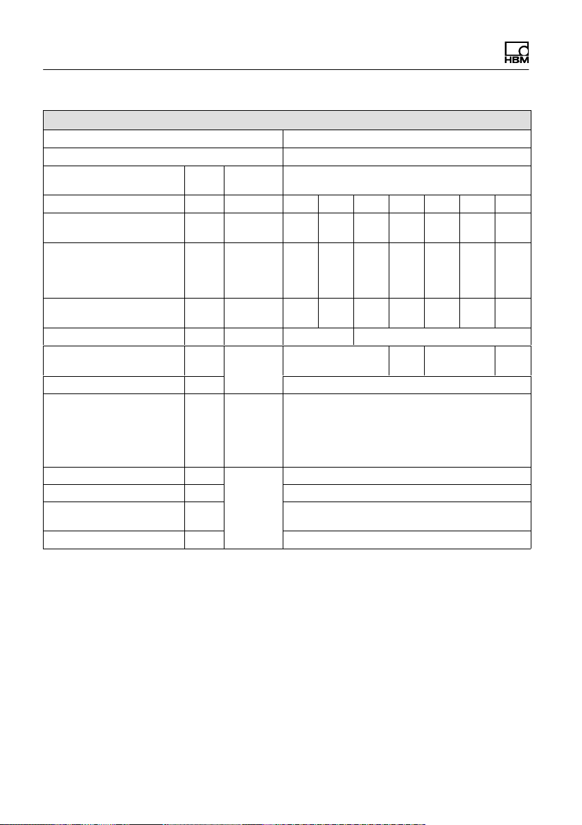
5 Specifications
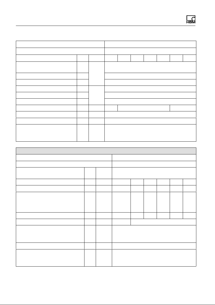
SP4M-C3MR, Capacity 1 … 20 kg
Type SP4M...
Accuracy class1) C3 Multi Range (MR)
Number of load cell verification
intervals
nLC 3000
Maximum capacity2) Emax kg 1 3 5 7 10 15 20
Minimum load cell verification
interval
vmin g 0.1 0.2 0.5 0.5 1 1 2
Temperature coefficient of zero
signal
TC0% of Cn
/10 K
"0.0140
"0.0093
"0.0140
"0.0100
"0.0140
"0.0093
"0.0140
Ratio of minimum verification
interval
Y 10,000 15,000 10,000 14,000 10,000 15,000 10,000
Maximum platform size mm 300 300 450 450
Nominal sensitivity
Maximum capacity 1 kg
Maximum capacities 3 kg...200 kg
CnmV/V 1.8 +0.27 -0.18 (Option 6: A1 = 1.8 mV/V±0.1 %)
2.0±0.2 (Option 6: A = 2mV/V±0.1 %)
Zero signal mV/V 0"0.1
Temperature coefficient of
sensitivity3)
Temperature range +20 °C ... +40 °C
-10 °C ... +20 °C
TCS% of
Cn/10 K "0.0170
"0.0110
Non-linearity3) dlin
% of Cn
"0.0166
Relative reversibility error3) dhy "0.0166
Minimum dead load output return
(MDLOR)
"0.0166
Off-center load error4, as per OIML
R76
"0.0233
Input resistance RLC W300...500
Output resistance R0300...500 (Option 6: A = 410 W"0.2 W)
Reference voltage Uref
V
5
Nominal (rated) range of the
excitation voltage
BU1 ... 12
Max. excitation voltage 15
Insulation resistance at 100 VDC Ris GW>2
Specifications
14 A2447-1.1 HBM: public SP4M
Type SP4M...
Accuracy class1) C3 Multi Range (MR)
Maximum capacity2) 2015107531kgEmax
Nominal (rated) range of the
ambient temperature
BT
°C
-10 ... +40
Operating temperature range Btu -10 ... +50
Storage temperature range Btl -25 ... +70
Limit load EL% of
Emax
150
Limit lateral loading, static Elq 300
Breaking load Ed300
Rated displacement at Emax, approx. snom mm < 0.5 < 0.3 < 0.25
Weight, approx. m kg 0.45
Degree of protection5IP67
Material: Measuring body
Application protection
Cable sheath
Aluminum
Silicone rubber
PVC
SP4M-C3MR, Capacity 1 … 20 kg
Type SP4M...
Accuracy class1) C3 Multi Range (MR)
Number of load cell verification
intervals
nLC 3000
Maximum capacity2) Emax kg 30 50 75 100 150 200
Minimum load cell verification interval vmin g 2 5 5 10 10 20
Temperature coefficient of zero signal
TC0% of Cn
/10 K
"0.0093
"0.0140
"0.0093
"0.0140
"0.0093
"0.0140
Ratio of minimum verification interval Y 15,000 10,000 15,000 10,000 15,000 10,000
Maximum platform size mm 450 450 600 600
Nominal sensitivity
Maximum capacity 1 kg
Maximum capacities 3 kg...200 kg
CnmV/V 1.8 +0.27 -0.18 (Option 6: A1 = 1.8 mV/V±0.1 %)
2.0±0.2 (Option 6: A = 2mV/V±0.1 %)
Zero signal mV/V 0"0.1
Temperature coefficient of sensitivity3)
Temperature range +20 °C ... +40 °C
-10 °C ... +20 °C
TCS% of
Cn/10 K "0.0170
"0.0110

Specifications
SP4M A2447-1.1 HBM: public 15
Type SP4M...
Accuracy class1) C3 Multi Range (MR)
Maximum capacity2) 200150100755030kgEmax
Non-linearity3dlin
% of Cn
"0.0166
Relative reversibility error3) dhy "0.0166
Minimum dead load output return
(MDLOR)
"0.0166
Off-center load error4, as per OIML R76 "0.0233
Input resistance RLC W300...500
Output resistance R0300...500 (Option 6: A = 410 W"0.2 W)
Reference voltage Uref
V
5
Nominal (rated) range of the
excitation voltage
BU1 ... 12
Max. excitation voltage 15
Insulation resistance at 100 VDC Ris GW>2
Nominal (rated) range of the
ambient temperature
BT
°C
-10 ... +40
Operating temperature range Btu -10 ... +50
Storage temperature range Btl -25 ... +70
Limit load EL% of
Emax
150
Limit lateral loading, static Elq 300
Breaking load Ed300
Rated displacement at Emax, approx. snom mm < 0.25
Weight, approx. m kg 0.45
Degree of protection5) IP67
Material: Measuring body
Application protection
Cable sheath
Aluminum
Silicone rubber
PVC
1) As per OIML R60, with PLC = 0.7
2) Max. eccentric loading as per OIML R76.
3) If the values for non-linearity (dlin), relative reversibility error (dhy) and temperature coefficient of
sensitivity (TCS) are added together, they are within the cumulated error limit specified in OIML
R60.
4) As per OIML R76
5) As per EN 60 529 (IEC 529)
Specifications
16 A2447-1.1 HBM: public SP4M
SP4M-C6MR, Capacity 7 … 36 kg
Type SP4M…
Accuracy class1) C6 Multi Range (MR)
Number of load cell
verification intervals nLC 6000
Maximum capacity2) Emax kg 7 10 15 18 20 30 36
Minimum load cell
verification interval vmin g 0.5 0.5 1 1 1 2 2
Temperature coefficient
of zero signal TC0% of
Cn/10 K
"0.0100
"0.0070
"0.0093
"0.0077
"0.0070
"0.0093
"0.0077
Ratio of minimum verification
interval Y 14,000 20,000 15,000 18,000 20,000 15,000 18,000
Max. platform size mm 300 x 300 450 x 450
Nominal sensitivity CnmV/V 2.0 ±0.2 1.8
±0.18 2.0 ±0.2 2.4
±0.24
Zero signal 0"0.10
Temperature coefficient of
sensitivity3)
Temperature range:
+20 ... +40 °C
-10 ... +20 °C
TCS% of
Cn/10 K ±0.0087
±0.0058
Relative reversibility error 3) dhy
% of Cn
±0.0083
Non-linearity 3) dlin ±0.0083
Minimum dead load output
return (MDLOR) ±0.0083
Off-center load error4) ±0.0116
1) As per OIML R60, with PLC = 0.7
2) Max. eccentric loading as per OIML R76.
3) The values for non-linearity (dlin), relative reversibility error (dhy) and temperature coefficient of
sensitivity (TCS) are recommended values. If these values are added together, they are within the
cumulated error limit specified in OIML R60.
4) As per OIML R76
For more specifications, see table SP4M..., accuracy
class C3MR (page 13)
Dimensions
SP4M A2447-1.1 HBM: public 17
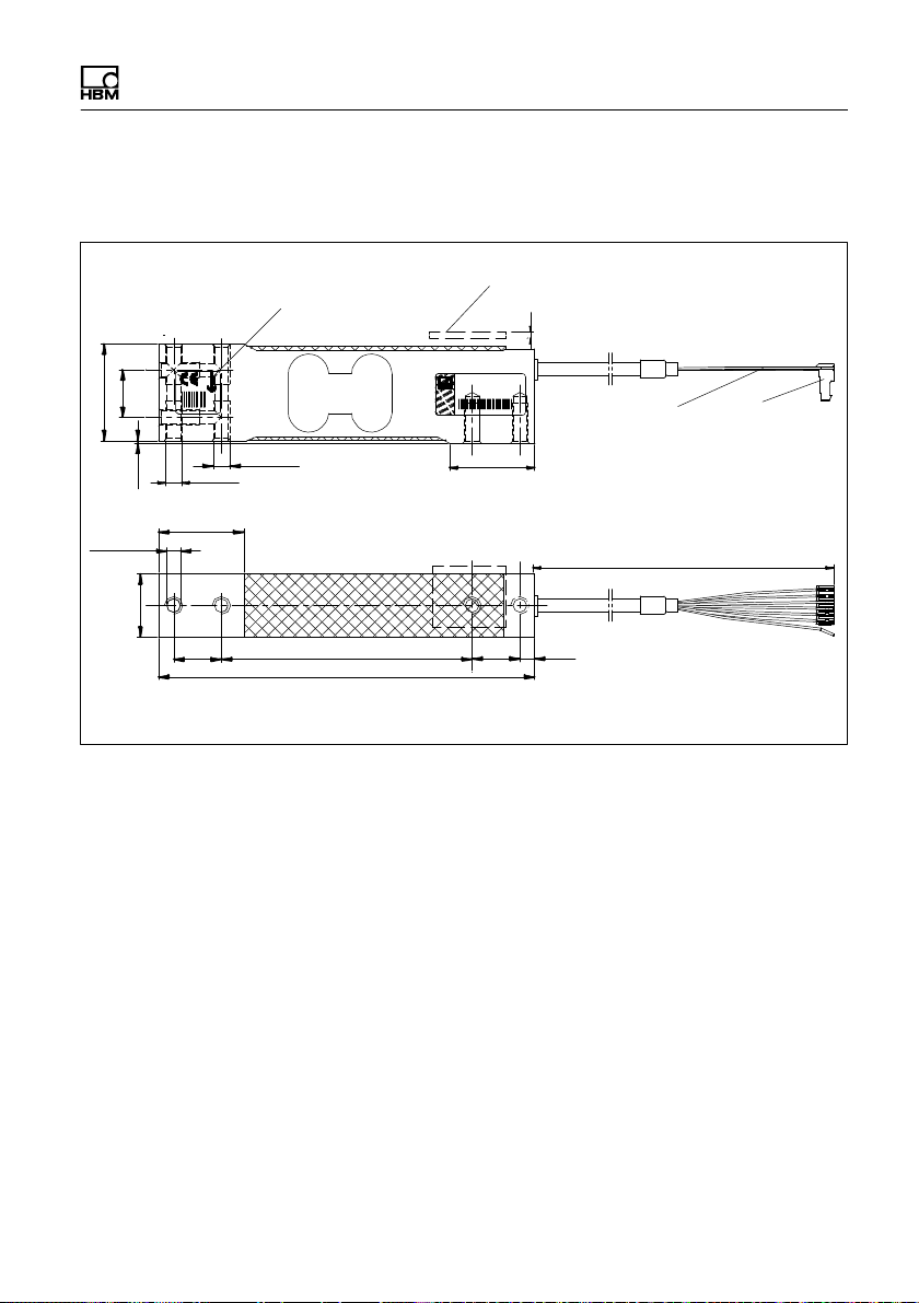
6 Dimensions
6‐M6x1‐6H,
16 deep Round cable 3000"50 mm
Cable and plug (see chapter 4
“Electrical connection”, page 10)
12345678 week
year
v
19.1
M6x0.5, 16 deep
M6x1‐6H
34
35
39
25.4*
19.1 99.6 19.1 6.1
150
Load direction
SP4C3‐MR 20kg
* SP4M.../1 kg: 18 mm
x4
Cover with ATEX, Zone 1 and 21;
Zone 2 and 22 (31 mm x 25 mm)
1+0.1
-0

Dimensions
18 A2447-1.1 HBM: public SP4M
This manual suits for next models
2
Table of contents
Languages:


