2
Table of Contents
1
Using This Guide ............................................................................................................................................................................................... 3
1.1
Purpose.......................................................................................................................................................................................................... 3
1.2
Additional ocumentation .............................................................................................................................................................................. 3
1.3
isclaimer....................................................................................................................................................................................................... 3
2
Physical Description ......................................................................................................................................................................................... 4
2.1
Front Panel..................................................................................................................................................................................................... 4
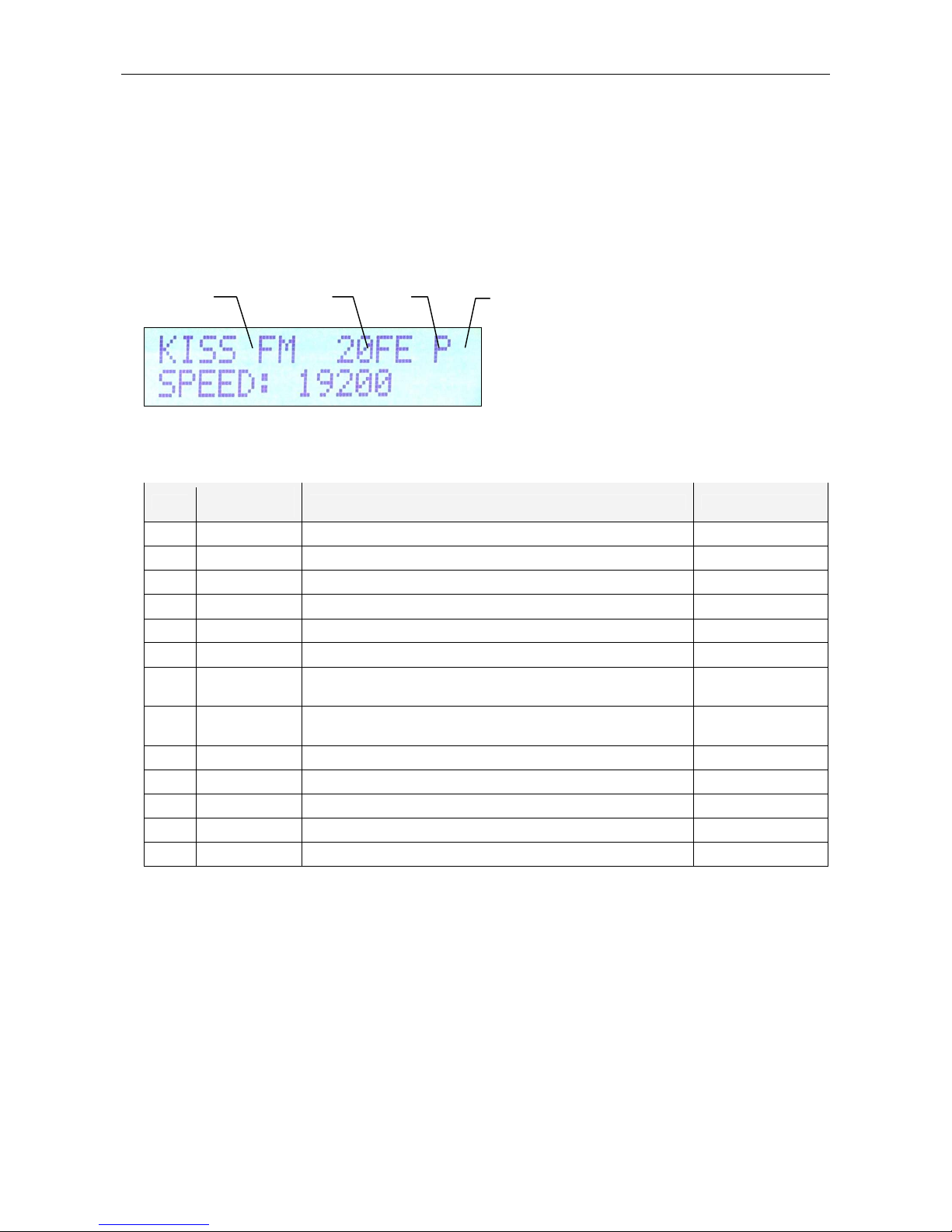
2.1.1
Status LC ............................................................................................................................................................................................... 4
2.1.2
LE indicators.......................................................................................................................................................................................... 5
2.2
Rear Panel ..................................................................................................................................................................................................... 5
3
Hardware Installation ........................................................................................................................................................................................ 6
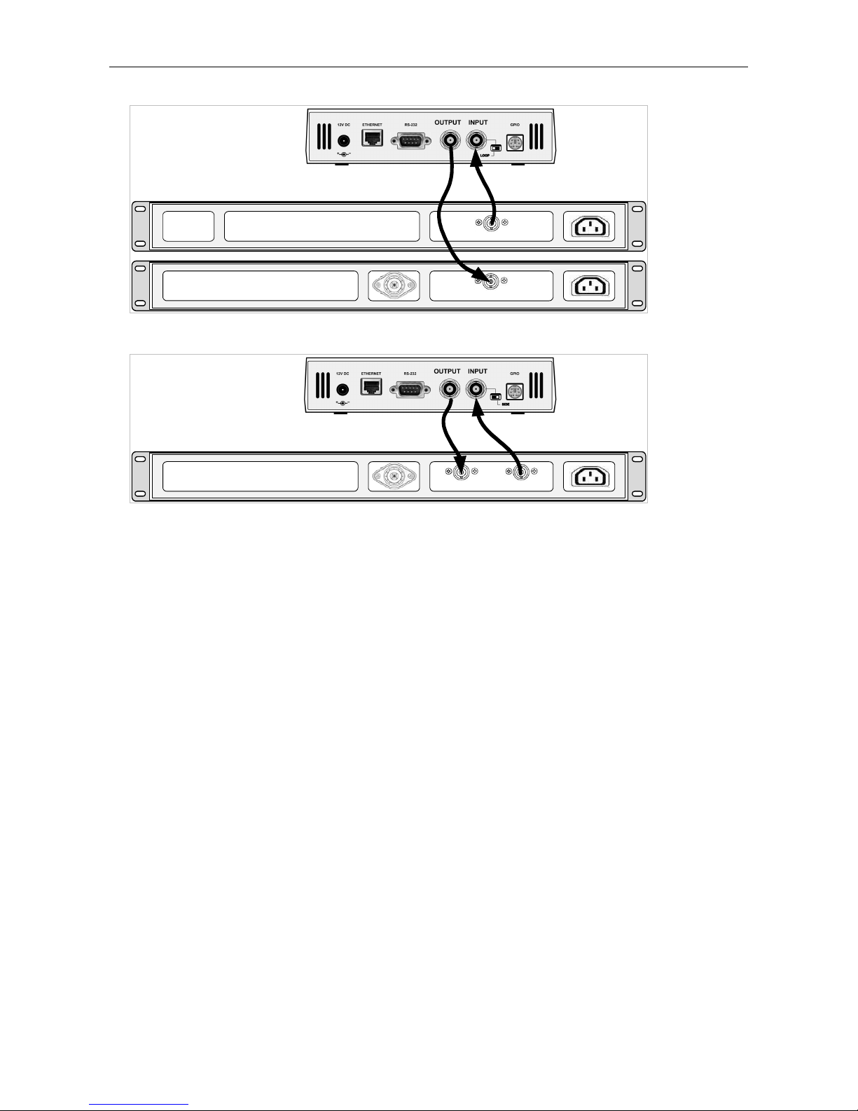
3.1
Connecting the R S Encoder........................................................................................................................................................................ 6
3.2
Hardware Settings.......................................................................................................................................................................................... 7
3.2.1
On-board adjustable elements................................................................................................................................................................. 7
3.2.2
Loop/Side switch...................................................................................................................................................................................... 7
3.3
Power Supply ................................................................................................................................................................................................. 8
3.4
Connecting the R S Encoder to a Local PC or a CE evice ..................................................................................................................... 8
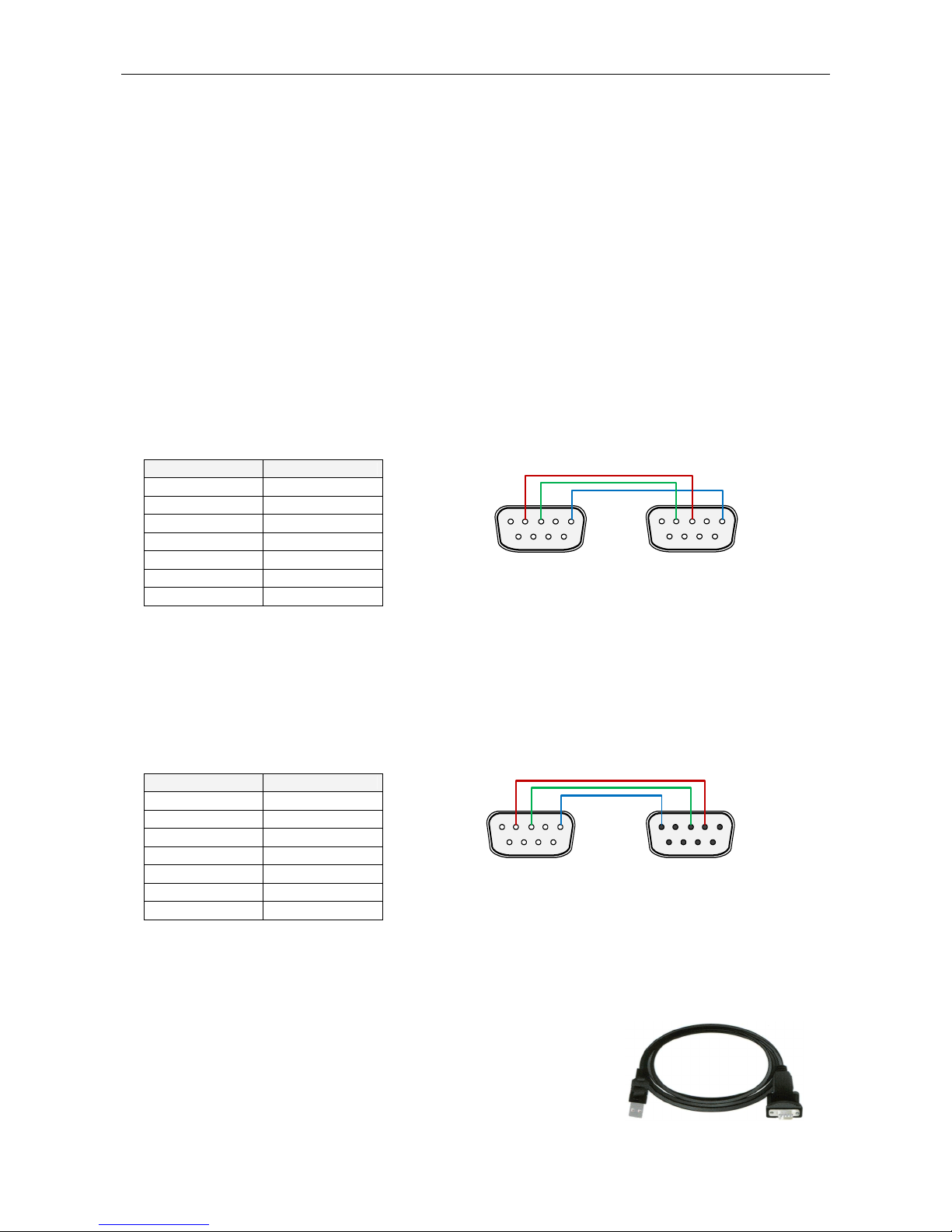
3.4.1
Connection to a serial port of the PC....................................................................................................................................................... 8
3.4.2
Connection to a CE device.................................................................................................................................................................... 8
3.4.3
Connection to a USB port of the PC ........................................................................................................................................................ 8
3.5
R S Level Adjustment................................................................................................................................................................................... 9
4
oftware Installation........................................................................................................................................................................................ 10
4.1
Establishing a First Communication with the R S Encoder ........................................................................................................................ 10
4.2
Remote Configuration of the R S Encoder................................................................................................................................................. 11
4.2.1
Finding out actual R S encoder’s IP address....................................................................................................................................... 11
4.2.2
Remote configuration of the R S encoder using internal website ........................................................................................................ 11
4.2.3
Remote configuration of the R S encoder using the Windows control software .................................................................................. 11
4.3
evice Setup................................................................................................................................................................................................ 12
4.3.1
evice Setup from the Magic R S ........................................................................................................................................................ 12
4.4
Setting Basic R S ata ............................................................................................................................................................................... 14
4.4.1
PI (Program Identification) ..................................................................................................................................................................... 14
4.4.2
PS (Program Service name).................................................................................................................................................................. 14
4.4.3
PTY (Program Type).............................................................................................................................................................................. 14
4.4.4
TP (Traffic Program) .............................................................................................................................................................................. 15
4.4.5
MS (Music/Speech)................................................................................................................................................................................ 15
4.4.6
AF (Alternative Frequencies) ................................................................................................................................................................. 15
5
Broadcast Automation ystem Link-up ........................................................................................................................................................ 16
5.1
Indirect Link.................................................................................................................................................................................................. 16
5.2
irect Link .................................................................................................................................................................................................... 16
5.2.1
Recommended procedure step-by-step................................................................................................................................................. 16
5.2.2
Compatibility commands and UECP...................................................................................................................................................... 16