Telguard TG-KIT LTE User manual
56050701
INSTRUCTIONS for TG-KIT LTE
Conversion of TG-7 Series to Telguard TG-7 LTE
The TelguardTG-KIT LTE can be used to convert an
older TG-7 series device (2G, 3G/4G, or CDMA) to a
comparable TG-7 LTE model.
Pre-Installation checklist:
Four (4) standoffs.
Four (4) mounting screws.
One (1) washer.
One (1) metal plate
NEW TG-7 LTE circuit board
Terminal Blocks
Labels
Conversion Procedure:
Note: Prior to beginning the hardware conversion,
identify the type of enclosure you are dealing with. If
the P/N of the original unit ends in 001, you have a
“Legacy” unit.
A. Disconnect all power to the Telguard unit. This
includes both AC power transformer and battery.
If the unit is a Legacy device, then a metal plate
(included) is needed to convert the dual board
chassis to a single board chassis.
B. Remove the TG7 circuit card(s) from chassis by
doing the following steps:
1. Disconnect the wires from terminal block.
2. Disconnect the antenna (or antenna cable
if dealing with a TG-7A).
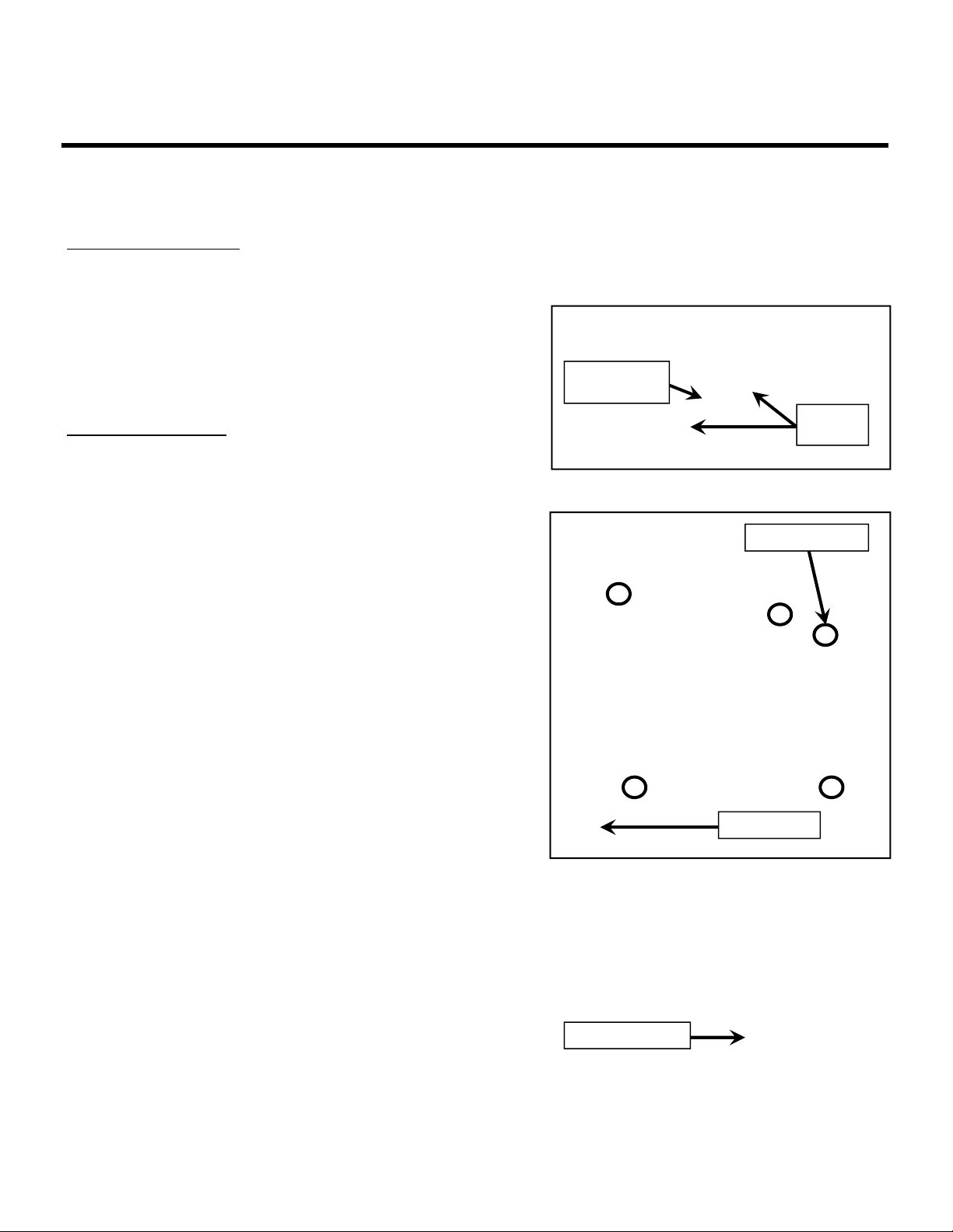
3. Remove the antenna TNC connector’s
retaining nut and washer. Set these aside
for later use. (Figure 1)
If the unit is a Legacy 2G device, the
daughter cards are secured with small
brackets. Unscrew these brackets to
remove these cards.
4. Remove all the screws securing the current
circuit board.
If the unit is a Legacy 2G device, you
will have four mounting screws and a
green grounding screw (Figure 2).
For other models there are only three
mounting screws in addition to the
grounding screw.
5. Set aside these mounting screws for future
use and remove old circuit board.
For Legacy 2G devices, you may need
to first remove the Modem card. If so,
set Modem Card and bracket screws
aside for later use. (Figure 2)
6. If you have a Legacy 2G TG-7A you must
remove the antenna bracket. (Figure 3)
Figure 1.
Figure 2.
Figure 3.
Bracket
Screws
Antenna
retaining nut
Modem Card
Mounting Screws
Antenna Bracket

56050701
C. If you have a Legacy 2G unit, you must first install
the metal plate:
1. Remove the metal plate and hardware
from the shipping box.
If you have a Legacy 2G TG-7A, skip
steps 2 and 3. Simply line up the holes
using the notch on the plate and the
antenna bracket screws as a reference.
2. Install the 4 standoffs in the holes that
originally held the board.
3. Line up the notch on the plate to where the
TNC chassis opening is.
4. Using the old board’s mounting screws,
install the metal plate. (Figure 4)
Once the metal plate is installed, line up the NEW
board with the 4 standoffs on the metal plate.
Using the provided screws secure the board to the
metal plate. (Figure 5)
D. If your device is NOT a Legacy 2G unit, install the
NEW circuit board into the chassis using the
provided screws. Use any of the provided mounting
screws to ground the unit.
E. Place the large washer from the kit over the
protruding TNC connector and secure the TNC
connector by installing the original retaining washer
and nut. (Figure 6)
F. If your Legacy 2G TG-7 had a Modem Card, make
sure to cover the hole left by its mounting bracket.
1. Remove the Modem Card from the bracket
by removing the two screws that hold them
together. (Figure 7A)
2. Once you have the bracket separated from
the Modem card, remount it onto the
chassis using the same bracket screws
from step B. (Figure 7B)
G. Wire the terminal blocks using the new door label
wiring guides
H. Install new door and Serial Number labels over
existing labels for future reference.
Figure 4.
Figure 5.
Figure 6.
Figure 7.
Refer to Installation & Operating Instructions
Manual for the Telguard conversion kit for any
additional information required.
Line up
notch
Standoffs
Large
washer Antenna
retaining nut
Modem Card screws
Modem Card
bracket
screws
Modem Card
bracket
7A
7B
Popular Media Converter manuals by other brands


H&B
H&B TX-100 Installation and instruction manual

Bolin Technology
Bolin Technology D Series user manual

IFM Electronic
IFM Electronic Efector 400 RN30 Series Device manual

GRASS VALLEY
GRASS VALLEY KUDOSPRO ULC2000 user manual

Linear Technology
Linear Technology DC1523A Demo Manual

Lika
Lika ROTAPULS I28 Series quick start guide

Weidmuller
Weidmuller IE-MC-VL Series Hardware installation guide

Optical Systems Design
Optical Systems Design OSD2139 Series Operator's manual

Tema Telecomunicazioni
Tema Telecomunicazioni AD615/S product manual

KTI Networks
KTI Networks KGC-352 Series installation guide

Gira
Gira 0588 Series operating instructions

Lika
Lika SFA-5000-FD user guide