Datasensor S65-PA-5-Z User manual

S65-PA-5-Z
Line sensor
INSTRUCTION MANUAL
CONTROLS
OUTPUT LED
The yellow LED ON indicates that the NO output is closed.
DISPLAY (green-coloured display)
The display indicates the value of the measurement detected [operating mode function].
Please refer to the following paragraphs for the correct indications to follow during the acquisition or
setting phase.
M1, M2 LEDs
The LED couple visualises the operating mode according to the table given below:
OPERATING MODE M1 LED M2 LED
Object beg. – Object end OFF OFF
Object centre position OFF ON
Width measurement ON OFF
Area ON ON
ALARM LED
The blinking of the alarm LED indicates that the received signal is insufficient for the correct sensor
functioning. In this case the “digital alarm” output is activated.
SET PUSH-BUTTON
Pressing the push-button for at least 2 seconds activates the self-setting procedure (2 thresholds =>
2 phases).
A long pressure on the button (at least 6 seconds) allows the user to access into the sensor
parameter setting menu.
Please refer to the following paragraphs for the correct indications to follow during the parameter
setting phase.
+/- PUSH-BUTTONS
Pressing the + or – push-buttons for at least 2 seconds allows the user to access into the manual
adjustment mode of the 2 switching thresholds.
The contemporary pressure on the + and – push-buttons (at least 2 seconds) activates the
acquisition procedure of the working area map.
The contemporary pressure on the + and – push-buttons (at least 6 seconds) activates the setting
procedure of the reflecting tape characteristics.
Please refer to the following paragraphs for the correct indications to follow during functioning.
INSTALLATION
The sensor can be mounted by means of the three housing’s holes
using two screws (M4x35 or longer) with washers.
Various orientable fixing brackets to ease the sensor positioning
are available (please refer to the accessories listed in the
catalogue).
The operating distance is measured from the front surface of the
sensor optics.
The M12 connector can be oriented at three different positions
using the specific fastening spring and rotating the block of 180°.
DIMENSIONS
mm
OUTPUT LED
42
42
50
18x45° 2
50
1411 5.5
25
31.6516
M12
15
20 17.05
7.75
DISPLAY
M1 LED
SET PUSHBUTTON
+/- PUSHBUTTON
-
+
SET
ALARM LED M2 LED
A1 2
OUT
TECHNICAL DATA
Power supply: 10 … 30 Vdc limit values
Ripple: 2 Vpp max.
Consumption (output current excluded): 70 mA max.
Outputs: 1 PNP or NPN output
30 Vdc max. (short circuit protection)
1 PNP or NPN alarm output
30 Vdc max. (short circuit protection)
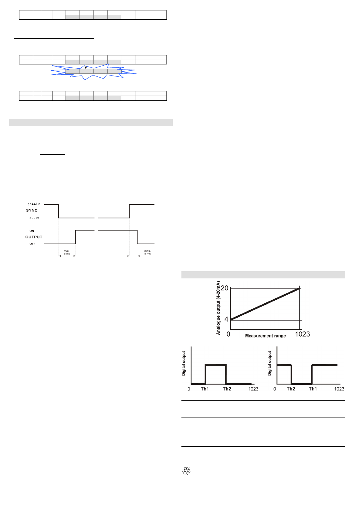
4-20mA analogue output
Serial interface: RS485, 9600B, 8, N, 1
SYNC input: PNP
Output current: 100 mA max.
Output saturation voltage: ≤2 V
Switching frequency: > 130 Hz
Indicators: 4 digit display (GREEN), OUTPUT LED (YELLOW)
1 ALARM LED (GREEN)
2 LEDs (M1, M2) operating mode (GREEN)
Setting: +, -, SET push-buttons
Data retention: non volatile EEPROM memory
Operating temperature: -10 … 55 °C
Storage temperature: -20 … 70 °C
Electrical protection: Class 2
Operating distance (typical values): 200 mm
Measurement range: 150 mm
Minimum object detectable: 0.9 mm
Resol ution : 0.15 mm
Linearity: 1%max.
Emission type: infared (875nm)
Ambient light rejection: according to EN 60947-5-2
Vibrations:0.5 mm amplitude, 10 … 55 Hz frequency, for each
axis (EN60068-2-6)
Shock resistance: 11 ms (30 G) 6 shock for each axis (EN60068-2-27)
Housing material: ABS
Lens material: Glass window and lenses
Mechanical protection: IP67 (TYPE 1 ENCLOSURE)
Connections: 8-pole M12 connector
Weight: 100 g. max.
CONNECTION
M12 CONNECTOR
*
Available only for the versions with RS485 serial interface (S65-PA-5-Z09-xxxZ).
NOTE: The wire colours are referred to the cables manufactured according to the European
standard.
FUNCTIONING
The S65-PA-5-Z sensor is a line sensor.
The typical functioning diagram is shown in the drawing given below. The object to detect is placed in
front of the sensor and the reflecting tape (inside the package) behind the sensor. The sensor
illuminated with IR lights the tape and receives the reflected light on a photodiode array. Each object
placed between the reflecting tape and the sensor is naturally detected as a dark spot on a luminous
background.
The sensor has 5 operating modes:
• Object beg.: the position of the first object edge is detected
• Object end: the position of the second object edge is detected
• Object centre: the centre of the object is measured
• Width: the distance between the first and last object edge is measured
• Area: the sum of all the object obscured zones is measured
The following diagram shows the sensor output according to the possible object position inside the
meaurement zone.
First ob. edge Last ob. edge Center Width Area
A
AA
A
Beg End (Beg+End)/2 End-Beg End-Beg
B
BB
B
End End 0 0 End
C
CC
C
Beg Beg 0 0 1023-Beg
D
DD
D
0 0 0 0 1023
E
EE
E
0 0 0 0 0
APPLICATION NOTES
The drawing shows how the same object can generate
different obscured zones if placed in different positions
inside the sensor working zone. The same happens if
the object is placed at different distances.
The “Area” operating mode is particularly sensitve to the
reflecting tape’s characteristics and for this reason the
sensor can detect the main specifications of the tape
used (please refer to “Advanced functions” paragraph”).
*
*

SETTING OF THE 2 THRESHOLDS
The sensor setting is effected placing the object to detect directly in front of the sensor following the
procedure given below:
zpush-button pressed {push-button not pressed
LED on LED off
- Obect detection at OFF/ON output switching
- Position the object inside the measurement area to define the measurement value (depending
on the operating mode used) corresponding to the OFF/ON switching of the digital output.
Display Keyboard
OUT A M1 M2 Dig1 Dig2 Dig3 Dig4 + SET -
4 5 0 {z{
- Press the SET push-button for at least 2s.
- The detected value for the first switching threshold appears (4Hz blinking until the SET push-
button is released).
- The value acquired can be changed using the +/- push-buttons.
OUT A M1 M2 Dig1 Dig2 Dig3 Dig4 + SET -
4 5 0 z{z
- The units change if these push-buttons are pressed repeatedly, the tens if kept pressed.
- Press the SET push-button again for at least 0.5 s. to end the detection phase of the first
switching threshold.
OUT A M1 M2 Dig1 Dig2 Dig3 Dig4 + SET -
4 5 0 {z{
- Obect detection at ON/OFF output switching
- Position the object inside the measurement area to define the measurement value (depending on
the operating mode used) corresponding to the ON/OFF switching of the digital output.
-
The detected value for the second switching threshold appears.
-
OUT A M1 M2 Dig1 Dig2 Dig3 Dig4 + SET -
6 0 0 {z{
- The present value appears (4Hz blinking).
- Press the SET push-button again for at least 0.5 s. to detect the second switching threshold.
OUT A M1 M2 Dig1 Dig2 Dig3 Dig4 + SET -
6 0 0 {z{
- The detected value for the second switching threshold appears.
- The value acquired can be changed using the +/- push-buttons.
OUT A M1 M2 Dig1 Dig2 Dig3 Dig4 + SET -
6 0 0 z{z
- The units change if these push-buttons are pressed repeatedly, the tens if kept pressed.
- Press the SET push-button again for at least 0.5 s. to end the detection phase.
OUT A M1 M2 Dig1 Dig2 Dig3 Dig4 + SET -
6 0 0 {z{
SWITCHING THRESHOLD ADJUSTMENT
Display Keyboard
OUT A M1 M2 Dig1 Dig2 Dig3 Dig4 + SET -
0 4 5 0 z{z
- Press one of the +/- push-buttons for at least 2 s.
- The “tH-1” message appears.
OUT A M1 M2 Dig1 Dig2 Dig3 Dig4 + SET -
t H - 1 {{{
- Switching threshold selection
- Use the +/- push-buttons to select the switching threshold.
OUT A M1 M2 Dig1 Dig2 Dig3 Dig4 + SET -
t H - 1 z{z
t H - 2 z{z
- Adjustment phase of the switching threshold
- Press the SET push-button for at least 0.5 s.
- The previously detected value appears.
- The value can be changed using the +/- push-buttons.
- The units change if these push-buttons are pressed repeatedly, the tens if kept pressed.
OUT A M1 M2 Dig1 Dig2 Dig3 Dig4 + SET -
0 6 0 0 z{z
- Press the SET push-button again for at least 0.5 s. to end the adjustment phase.
OUT A M1 M2 Dig1 Dig2 Dig3 Dig4 + SET -
0 4 5 0 {z{
SETTING OF THE PARAMETERS
Display Keyboard
OUT A M1 M2 Dig1 Dig2 Dig3 Dig4 + SET -
4 5 0 {z{
Press the SET push-button for at least 6s to enter into the parameter setting mode.
The "MEnu" message appears.
OUT A M1 M2 Dig1 Dig2 Dig3 Dig4 + SET -
M E n u {{{
- Pressing the + and –push-buttons the user can run up and down the menu, reading the
following messages.
- Functioning mode selection
- At each pressure on the SET push-button the user can run through the options of the selected
level.
OUT A M1 M2 Dig1 Dig2 Dig3 Dig4 + SET -
E n d z{z
b E G {z{
c E n t {z{
W I d t {z{
A r E A {z{
- Delay setting
- At each pressure on the SET push-button the user can run through the options of the selected
level.
OUT A M1 M2 Dig1 Dig2 Dig3 Dig4 + SET -
d - 0 0 z{z
d - 0 5 {z{
d - 1 0 {z{
d - 2 0 {z{
d - 3 0 {z{
d - 4 0 {z{
- The setting of the delay value is in common to both outputs.
When the delay value set is different from zero, the outputs will remain active for a minimum
time equal to the number of milliseconds visualised on the display.
- Visualisation of the threshold 1 data
- Pressing the SET push-button the value of the threshold 1 appears.
OUT A M1 M2 Dig1 Dig2 Dig3 Dig4 + SET -
t H - 1 z{z
THRESHOLD 0 4 5 0 {z{
- Visualisation of the threshold 2 data
- Pressing the SET push-button the value of the threshold 2 appears.
OUT A M1 M2 Dig1 Dig2 Dig3 Dig4 + SET -
t H - 2 z{z
THRESHOLD 6 0 0 {z{
- Visualsation of the operating area status
- Pressing the SET push-button the operating area status. More precisely; if “FULL” the operating
area is complete, if “REDU“ the acquired area is not complete, but presents some zones that do
not have to be detected .
OUT A M1 M2 Dig1 Dig2 Dig3 Dig4 + SET -
F U L L z{z
or
r E d U z{z
- Reset of the sensor default configuration
- Pressing the SET push-button (the “RESE” message blinks for 2s, 4Hz) the default configuration
is re-set and the user exits from the menu, returning to the normal mode. The default
configuration is: “beg object” operating mode, delay 0, Th1 switching threshold = 100, Th2 =
200.
OUT A M1 M2 Dig1 Dig2 Dig3 Dig4 + SET -
r E S E z{z
r E S E {z{
- Memorisation of the parameters set
- Pressing the SET push-button (the “SAVE” message blinks for 2s, 4Hz) all the modified values
are memorised and the user exits form the menu,returning to the normal mode.
OUT A M1 M2 Dig1 Dig2 Dig3 Dig4 + SET -
S A V E z{z
S A V E {z{
- Press one of the +/- push-buttons the user can return to the setting menu.
- Exit from the parameter setting menu
After 10s inactivity of the sensor push-buttons, the sensor returns to the normal operating mode
visualising the distance.
ADVANCED FUNCTIONS
Display Keyboard
OUT A M1 M2 Dig1 Dig2 Dig3 Dig4 + SET -
0 4 5 0 z{z
- Operating area selection
- Press contemporarily the + and – push-buttons for at least 2s.
- The “W_Ar” message appears.
OUT A M1 M2 Dig1 Dig2 Dig3 Dig4 + SET -
W _ A r {{{
W _ A r {z{
- The operating area configuration is memorised when the push-buttons are released (the W_Ar
blinks for 2s, 4Hz) and the sensor returns to the normal mode.
OUT A M1 M2 Dig1 Dig2 Dig3 Dig4 + SET -
0 4 5 0 {{{
-
This operation is necessary when objects, inside the operating area, must not be detected.
- Detection of the reflecting tape characteristics
- Press contemporily the + and – push-buttons for at least 6s.
- The “TAPE” message appears.
OUT A M1 M2 Dig1 Dig2 Dig3 Dig4 + SET -
t A p E {z{
t A p E {{{
- The reflecting tape characteristics are memorised when the push-buttons are released (the
“TAPE” message blinks for 2s, 4Hz) and the sensor returns to the normal mode.
OUT A M1 M2 Dig1 Dig2 Dig3 Dig4 + SET -
0 4 5 0 {{{
This operation is particularly suggested in the “AREA” operating mode as this mode is very sensitive
to the reflecting tape characteristics.
REMOTE FUNCTIONS
KEYLOCK
The keyboard block function is activated at powering on, connecting the SYNC terminal to the
positive power supply (+Vdc) for at least 1 s, and the push-buttons are NO LONGER active.
After the first second, the SYNC input is ready for the normal functioning and if the SYNC is passive
the outputs are deactivated.
To deactivate the keyboard block, the sensor has to be turned off and re-powered maintaining the
SYNC wire not connected or ground connected (GND).
SYNC input
The SYNC signal allows to determine precisely the beginning and end of the identification.
The identification cycle begins after the transition of the SYNC signal from passive to active and the
sensor outputs are updated after max. 8 ms.
All the outputs are deactivated after max. 8 ms from the active – passive transition.
The connection of the SYNC wire to +Vdc corresponds to the passive logic status while SYNC not
connected or connected to 0 V corresponds to the active.
RS485 serial connection (only for S65-PA-5-Z09-xxxZ versions)
The complete sensor remote control is obtained using a RS485 line.
All the functions, such as the threshold selection and functioning modes, can be accessed through
the serial line.
The serial communication parameters are: 9600 baud, non-parity, 8 data bits, 1 stop bit.
All the commands have to be sent via terminal in an ASCII format according to the folllowing
instructions.
- Reading of the sensor status:
At any moment, at the receipt of the ‘r <CR> <LF>’ command, the sensor configuration is returned.
- Reading of the measurement::
At any moment, at the receipt of the ‘v <CR> <LF>’ command, the value of the measurement made
by the sensor is returned, in the ‘xxxx<CR> <LF>’ format (the xxxx are four ASCII characters).
- Remote detection of the thresholds:
To access into the remote detection mode, the SYNC input has to remain passive for at least 300
ms. The commands available are:
@ <CR> <LF> beginning of the remote setting mode (together with SYNC passive)
cx<CR> <LF> threshold selection, with x ∈{1,2}
txxxx <CR> <LF> threshold value selection, with xxxx ∈{0..1023}
e <CR> <LF> memorisation of the configuration sequence.
q <CR> <LF> exit from the remote setting without saving the configuration.
If the SYNC input is activated before the ‘e’ (execute) command is given, the sensor exits the
remote setting mode without saving the configuration, similarly to the receipt of the ‘q’ (quit)
command.
If the SYNC input is active, at the receipt of the @ <CR> <LF> command, the sensor responds
with: ?? <CR> <LF>. At the receipt of the q <CR> <LF> or e <CR> <LF> commands, the sensor
transmits ok <CR> <LF>.
- Remote detection of the operating area:
To access into the remote detection mode, the SYNC input has to remain passive for at least 300
ms. The commands available are:
@ <CR> <LF> beginning of the remote setting mode (together with SYNC passive)
w <CR> <LF> acquisition command of the operating area
e <CR> <LF> memorisation of the configuration sequence.
q <CR> <LF> exit from the remote setting without saving the configuration.
If the SYNC input is activated before the ‘e’ (execute) command is given, the sensor exits the
remote setting mode without saving the configuration, similarly to the receipt of the ‘q’ (quit)
command.
If the SYNC input is active, at the receipt of the @ <CR> <LF> command, the sensor responds
with: ?? <CR> <LF>. At the receipt of the q <CR> <LF> or e <CR> <LF> commands, the sensor
transmits ok <CR> <LF>.
- Remote detection of the reflecting tape characteristics:
To access into the remote detection mode, the SYNC input has to remain passive for at least 300
ms. The commands available are:
@ <CR> <LF> beginning of the remote setting mode (together with SYNC passive)
u <CR> <LF> detection command of the reflecting tape characteristics
e <CR> <LF> memorisation of the configuration sequence.
q <CR> <LF> exit from the remote setting without saving the configuration.
If the SYNC input is activated before the ‘e’ (execute) command is given, the sensor exits the
remote setting mode without saving the configuration, similarly to the receipt of the ‘q’ (quit)
command.
If the SYNC input is active, at the receipt of the @ <CR> <LF> command, the sensor responds
with: ?? <CR> <LF>. At the receipt of the q <CR> <LF> or e <CR> <LF> commands, the sensor
transmits ok <CR> <LF>.
- Reset of the sensor default configuration:
To access into the remote detection mode, the SYNC input has to remain passive for at least 300
ms. The commands available are:
@ <CR> <LF> beginning of the remote setting mode (together with SYNC passive)
z <CR> <LF> default sensor configuration reset command
e <CR> <LF> memorisation of the configuration sequence.
q <CR> <LF> exit from the remote setting without saving the configuration.
If the SYNC input is activated before the ‘e’ (execute) command is given, the sensor exits the
remote setting mode without saving the configuration, similarly to the receipt of the ‘q’ (quit)
command.
If the SYNC input is active, at the receipt of the @ <CR> <LF> command, the sensor responds
with: ?? <CR> <LF>. At the receipt of the q <CR> <LF> or e <CR> <LF> commands, the sensor
transmits ok <CR> <LF>.
- Operating mode configuration:
To configure the operating mode, the SYNC input has to remain passive for at least 300 ms. The
commands available are:
@ <CR> <LF> beginning of the remote setting mode (together with SYNC passive)
mx<CR> <LF> operating mode selection, with x ∈{0, 1, 2, 3, 4}
m0 = end object position m3 = width measurement
m1 = beg object position m4 = area measurement
m2 = centre position
e <CR> <LF> memorisation of the configuration sequence.
q <CR> <LF> exit from the remote setting without saving the configuration.
If the SYNC input is activated before the ‘e’ (execute) command is given, the sensor exits the
remote setting mode without saving the configuration, similarly to the receipt of the ‘q’ (quit)
command.
If the SYNC input is active, at the receipt of the @ <CR> <LF> command, the sensor responds
with: ?? <CR> <LF>. At the receipt of the q <CR> <LF> or e <CR> <LF> commands, the sensor
transmits ok <CR> <LF>.
- Delay configuration:
To configure the delay, the SYNC input has to remain passive for at least 300 ms. The commands
available are:
@ <CR> <LF> beginning of the remote setting mode (together with SYNC passive)
dx<CR> <LF> delay selection, with x ∈{0,1,2,3,4,5}
d0 = 0 ms d3 = 20 ms
d1 = 5 ms d4 = 30 ms
d2 = 10 ms d5 = 40 ms
e <CR> <LF> memorisation of the configuration sequence.
q <CR> <LF> exit from the remote setting without saving the configuration.
If the SYNC input is activated before the ‘e’ (execute) command is given, the sensor exits the
remote setting mode without saving the configuration, similarly to the receipt of the ‘q’ (quit)
command.
If the SYNC input is active, at the receipt of the @ <CR> <LF> command, the sensor responds
with: ?? <CR> <LF>. At the receipt of the q <CR> <LF> or e <CR> <LF> commands, the sensor
transmits ok <CR> <LF>.
NOTE: the single characters have to be distanced amongst themselves at least 1 ms, during
the command transmission.
DETECTION DIAGRAMS
DECLARATION OF CONFORMITY
We DATASENSOR S.p.A. declare under our sole responsibility that these products are conform to
the 89/336 CEE, 73/23 CEE Directives and successive amendments.
WARRANTY
DATASENSOR S.p.A. warrants its products to be free from defects.
DATASENSOR S.p.A. will repair or replace, free of charge, any product found to be defective during
the warranty period of 36 months from the manufacturing date.
This warranty does not cover damage or liability deriving from the improper application of
DATASENSOR products.
DATASENSOR S.p.A. Via Lavino 265
40050 Monte S. Pietro - Bologna - Italy
Tel: +39 051 6765611 Fax: +39 051 6759324
http://www.datasensor.com e-mail: info@datasensor.com
DATASENSOR S.p.A. cares for the environment: 100% recycled paper.
DATASENSOR S.p.A. reserves the right to make modifications and improvements without
prior notification.
826002010 Rev.00
Table of contents
Other Datasensor Accessories manuals


