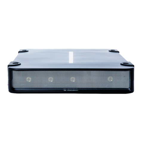
Dataton WATCHPAX 60 User manual

1.3
WATCHPAX 60
USER’S GUIDE

DATATON WATCHPAX 60 – USER’S GUIDE TABLE OF CONTENTS
1. INTRODUCTION 4
What’s WATCHOUT? 4
System Overview 5
WATCHPAX 60 In Your Rig 5
Display Devices 5
Start up Screen 5
Accessories 6
Supplied 6
Available Separately 6
Technical Data 7
Power 7
SSD 7
Environmental 7
Media Server Operating System 7
2. INSTALLATION AND OPERATION 8
Before Using Your WATCHPAX 60 8
Safety First 8
Ventilation 9
Installation 9
General 9
Standalone Installation 9
Installation in 19-inch Rack 9
Operation 9
First Power On 9
Power On 9
Power Off 9
Reset WATCHPAX 60 10
Reset and Keep User Data 10
Reset to Factory Settings 11
Reset Procedure 11
Delete Files 13
Rebuild Show Cache 13
3. QUICKSTART GUIDE 14
The Basics 14
Manage Network Settings 14
Set Native Resolution 15
Auto Start 15
4. SYNCHRONIZATION 16
External Timecode 16
GPU Synchronization – Models B, C 17
Congure GPU Synchronization 17
Interpret Status LEDs 18
Connect GPU Synchronization 19
SDI Synchronization – Model C Only 19
Mode 1: Internal Sync 19
Mode 2: SDI Sync Connector 19
Mode 3: SDI Connector 20
5. EDID MANAGEMENT 21
Access EDID management settings 21
Export EDID 22
Load EDID 23
Unload EDID 23
6. WATCHPAX 60 MODEL A 24
Technical Specication 24
Dimensions 24
Shipping Dimensions 24
Front View 24
Connectors 25
7. WATCHPAX 60 MODEL B 26
Technical Specication 26
Dimensions 26
Shipping Dimensions 26
Front View 26
Connectors 27
8. WATCHPAX 60 MODEL C 28
Technical Specication 28
Dimensions 28
Shipping dimensions 28
Front View 28
Connectors 29
9. WARRANTY, CONFORMITY AND
DISPOSAL 30
Limited Warranty 30
FCC Notice 31
Declaration Of Conformity 32
Disposal 33
DATATON WATCHPAX 60 – USER’S GUIDE

DATATON WATCHPAX 60 – USER’S GUIDE TABLE OF CONTENTS
10. SUPPORTED FORMATS 34
Video Capture Formats 34
HDMI Input 34
SDI Input 34
SDI Input Capture Formats (Models A, B) 34
The following SDI interfaces are supported. 34
SDI Input Capture Formats (Model c) 34
SDI Output Formats (Model C) 35
Analog Audio Output Formats 36
Adapters 37
HDCP 37
Playback Formats
Hardware Accelerated Video Formats 37
This manual is © Copyright 2019, DATATON
AB (“Dataton”). All rights reserved.
Dataton, the Dataton logo, WATCHPAX,
WATCHOUT and WATCHMAX are registered
trademarks/trademarks of DATATON AB. All
other company and product names are trade-
marks or registered trademarks of their respec-
tive owners. Use of a term in this publication
should not be regarded as affecting the validity
of any trademark.
The information in this manual has been checked
andisbelievedtobeaccurate.However,Dataton
assumes no responsibility for any inaccuracies
orerrorsinthismanualortheproductsdescribed.
In no event will Dataton be liable for direct,
indirect, special, incidental, or consequential
damages resulting from any defect or omission
in this manual, even if advised of the possibility
of such damages. The technical information
contained herein regarding features and
specicationsissubjecttochangewithoutnotice.
Products and manufacturers mentioned do not
constitute a recommendation or endorsement by
Dataton.
Document number: 3790/rev 1.0
Dataton AB, Teknikringen 22, 583 30 Linköping, Sweden
This manual refers to the "WATCHOUT USER'S
GUIDE."Downlad the latest version here:
https://www.dataton.com/support/user-guides

INTRODUCTION 4
1. INTRODUCTION
WATCHPAX 60 is a series of dedicated media servers available in three models (A, B, C). The server
offers four video outputs, SDI options, redundant power supply and a high-performance specication
designed solely with WATCHOUT shows in mind. The four DisplayPort outputs support 4K (UHD)
playback, making it a powerful and portable alternative in a multi-display setup.
WATCHPAX 60 is a locked-down unit, precongured for playback of WATCHOUT shows only. Multi-
ple units can be installed together in a rig or mixed with Dataton’s other media servers WATCHMAX,
WATCHPAX 20 and WATCHPAX 4.
WATCHPAX 60 has a compact, portable 2U form factor designed for tabletop or rack use (rack rails
and ears supplied separatly). Each unit weighs approximately 10 kg and has rugged, aluminium
housing with superior nish.
WHAT’S WATCHOUT?
Dataton WATCHOUT is the leading multi-display production and playback software. Use
WATCHOUT to orchestrate images, video, lighting, 3D and interactivity into a single impressive show.
The essential components of a WATCHOUT show are the software, media servers (such as
WATCHPAX 60) and display devices (projectors, LED displays, etc), running on a standard network.
In an operational setup, a WATCHOUT license key is required for the production computer running
the show and each media server. All Dataton-branded media servers, including the WATCHPAX 60,
have the license key built in.
WATCHOUT shows can be presented with multiple projectors for large, seamless images or used with
monitors, LED walls or other creative screen arrangements. WATCHOUT also has a strong set of pro-
jection and pixel-mapping features for applying content to complex three-dimensional objects.
Download WATCHOUT for free from the Dataton website: www.dataton.com

INTRODUCTION 5
SYSTEM OVERVIEW
WATCHPAX 60 is used as part of a WATCHOUT multi-display system.
Production
computer
Network switch
WATCHPAX 60
media server
A small WATCHOUT system with WATCHPAX 60
In the schematic above, there is a laptop (production computer) running WATCHOUT software and
equipped with a WATCHOUT license key. This connects to a network switch which, in turn, connects
to a Dataton WATCHPAX 60 media server. The WATCHPAX unit connects and manages the display
devices. In the example, these consist of four LED screens.
WATCHPAX 60 IN YOUR RIG
The WATCHPAX has four DisplayPort outputs. Used as is, it will manage four display devices in your
presentation. Splitters may also be used to increase the number of display devices managed. The
system is scalable; as the number of display devices increases, add more media servers to your rig.
To implement the bi-directional SDI in WATCHPAX 60 C model, please read “8. WATCHPAX 60
MODEL C”and “4. SYNCHRONIZATION”.
As all Dataton media servers (WATCHPAX or WATCHMAX ranges) have a built-in WATCHOUT
license, the only additional license key required is for your production computer. If you are not using a
Dataton media server (WATCHPAX or WATCHMAX) you will need a WATCHOUT license key for
each media server/display computer.
DISPLAY DEVICES
In the illustration above,four LED screens are used as the display devices. However, WATCHOUT can
be used with virtually any display device that can be connected to a computer (such as projectors,
LCD panels, LED walls etc).
START UP SCREEN
This is shown on all display devices connected to the WATCHPAX 60 at start-up, or if WATCHOUT has
been re-launched. There are three lines of information:

INTRODUCTION 6
First line: Computer and cluster name (if this has been set in the WATCHOUT Production software
Network window – please see the “Network Window” section in Chapter 3: Windows, “Dataton
WATCHOUT User’s Guide” for more information), IP address for the media server.
Second line: Version number of the WATCHOUT Display software that is currently installed on the
media server.
Third line: Media server model type, serial number, rmware version
ACCESSORIES
SUPPLIED
2 x power cords with IEC 60320 C13 connector for the redundant PSU
4 x Accell DisplayPort to HDMI 2.0 adapters
1 x audio XLR breakout cable
9 x micro BNC to BNC adapters (WATCHPAX 60C only)
Rubber feet (for tabletop/standalone use)
AVAILABLE SEPARATELY
Rack kit for mounting the unit to a 19” rack
Fan lter as a replaceable spare part
Micro BNC to BNC adapters
Unit with rails mounted for rack use
WATCHOUT start-up screen

INTRODUCTION 7
TECHNICAL DATA
POWER
Input: 90 V AC ~ 264 V AC, 47 Hz ~ 63 Hz, 2.0 A ~ 0.85 A
Power consumption 500W, 1710 BTU (absolute maximum 600W, 2050 BTU)
SSD
Standard: 1.9 TB.
Options: 3.8 TB, 7.6 TB.
ENVIRONMENTAL
Temperature range
Optimal ambient temperature range for operation 21 °C to 23 °C
Operating 0 °C to +40 °C
Storage and transportation -20 °C to +40 °C
Relative humidity
Optimal 45% to 50%
Operating 20% to 85 % (non-condensing)
Storage and transportation 10% to 90% (non-condensing)
Altitude
Operating, maximum 2000 meters above sea level
Noise
Approximately 50 dBA during normal operation
Remember that noise levels are perceived differently by different people. Bear this in mind when
choosing the installation site for your servers.
MEDIA SERVER OPERATING SYSTEM
The operating system in WATCHPAX 60 has been optimized and licensed for this specic media
server conguration.
Do not install or attempt to install any software on the locked-down media server (such as drivers,
software updates, security updates, virus protection, etc). Doing so will automatically void the unit’s
warranty.
For security reasons, media servers should always be installed and operate on a separate network,
without access to other networks.

INSTALLATION AND OPERATION 8
2. INSTALLATION AND OPERATION
BEFORE USING YOUR WATCHPAX 60
Please read the manual thoroughly before operation. Always check that the unit has not been dam-
aged in transit when you take delivery.
IMPORTANT: The WATCHPAX 60 is a plug-and-play unit. Do not open, modify or repair the unit your-
self. Opening, modifying (software or hardware) or repairing the unit yourself willl invalidate the war-
ranty and presents a risk for the user.
SAFETY FIRST
Thisproductmustbegrounded.Ensureyouconnectthepowerplug to a grounded power socket.
• Insert the power plug all the way in, so it is not loose.
• Do not place the power cord or product near heat sources.
• Caution: shock hazard if handled carelessly or inaccurately.
• Avoid installing the product in a narrow space with bad ventilation. Do not block the ventilation in
any way when operated. Always keep front and back of unit clear, minimum 200 mm.
• Keep the plastic packaging bag for the product in a place that can not be reached by children.
• Do not install the product on an unstable or vibrating surface.
• Install the unit in a clean, dry area without excessive particles or dust, in the air (preferably in an
air-conditioned server room). Do not install the product in a place where it is exposed to high tem-
perature, chemicals, dust, moisture, oil or smoke.
• Take care not to drop the product when moving it.
• When installing the product on a shelf, ensure the bottom edge of the product does not protrude to
avoid tipping or other potential mishaps.
• The wall socket should be easily accessible for pluggable equipment.
• High voltage runs through the product. Do not attempt to disassemble, repair, or modify the product on
your own. To move the product, rst disconnect all the cables from it.
• If the product generates a burning smell, or smoke, remove the power cords immediately and contact
Dataton.
• If the product falls, or the exterior is damaged, power off the product, remove the power cords and
contact Dataton.
• If there is a risk of thunderstorm or lightning strike, turn off the power and disconnect all cables.
• Do not insert a metallic object or inammable object into any opening of the product.
• Unplug this product from the AC power supply before cleaning. Do not use liquid or aerosol clean-
ers on the product. Use a microber cloth for cleaning.
• After storage in cold conditions, let the product adapt to normal temperature for two hours before
powering on.

INSTALLATION AND OPERATION 9
VENTILATION
Airow is critical for the correct operation of WATCHPAX 60. Do not install WATCHPAX 60 in a con-
ned space.
Air ows from the front of the unit to the rear (where the connectors are located). Always keep both
front and rear panels clear of obstruction at all times.
INSTALLATION
GENERAL
• This equipment is for professional use for installation at locations where only adults are normally
present. Check the “Safety First” list before use.
• The WATCHOUT 60 must be connected to a properly grounded wall socket (a socket-outlet with
protective earth connection in the building).
• Both power inlets should be connected when using the device to achieve redundancy.
• The serial number is located on the base of the unit.
STANDALONE INSTALLATION
Place the unit at.
Mount the four self-adhesive rubber feet (supplied) at the points indicated on the base of the unit.
INSTALLATION IN 19-INCH RACK
The WATCHPAX 60 unit may be mounted in a 19-inch rack by using the optional rack kit. Please refer
to separate instructions for rack kit assembly.
OPERATION
IMPORTANT: Only use the cables/adapters that are delivered with the WATCHPAX 60 unit, otherwise
Dataton AB cannot guarantee full functionality.
The WATCHPAX 60 has two IEC 60320 C14 power inlets and both should be connected when using
the device to achieve redundancy. To obtain full redundancy, we recommend that the two power feeds
come from different electrical feeds/phases. This reduces the risk of the unit failing if one of the electri-
cal feeds is lost.
FIRST POWER ON
The rst time you power up a WATCHPAX 60 (after delivery or after a reset) the system will nalize
installation and reboot several times. This procedure will typically take about 5 minutes to complete.
IMPORTANT: Do not interrupt this procedure. The rst power-on updates rmware of critical compo-
nents. Forcefully powering off the system during the conguration process might result in non-working
hardware components (i.e., capture devices will stop working).
POWER ON
The WATCHPAX 60 is turned on by inserting the DC power cords and then pressing the power button
on the front of the unit. Wake on LAN (WOL) may also be used.
POWER OFF
Powering down should be initiated from within WATCHOUT production software.

INSTALLATION AND OPERATION 10
When the power-off sequence is complete, the fans will turn off, and the power cords may be
removed.
There are three ways to power off from WATCHOUT, as described in the “Manage Display Com-
puter” section in Chapter 3: Windows, in the “Dataton WATCHOUT User’s Guide.”
• Use Manage Display Computer > Power Down found in the Stage main menu.
• Use the Manage Display Computer context menu when a display is selected on the Stage.
• Use the Remote Access to initiate shutdown directly from the media server.
NOTE: If you are unable to shut down via the software, you can force shutdown with the power button
as a last resort. Please be aware that this may cause data loss and system corruption. To force shut-
down in this way, press and hold the power button (located on the front of the media server) for at
least 5 seconds. The light will then turn off and the power is cut.
IMPORTANT: Do not unplug power cords during power-off as this may cause data loss and system
corruption.
RESET WATCHPAX 60
There are occasions when you may want to reset a WATCHPAX 60, for example, if the unit has been
corrupted, or if it’s a rental unit and user-specic info has to be removed between rentals.
There are two levels of reset:
• Reset and keep user data. This resets the operating system, display, GPU and capture settings but
retains user data, such as shows and media.
• Reset to factory settings. The takes the unit all the way back to the original factory settings‚ you lose
all user data.
IMPORTANT: A reset, regardless of level, is an advanced measure. Make sure you are fully aware of
what data you lose when you reset!
RESET AND KEEP USER DATA
This option resets the system partitions but keeps all user data such as:
• Shows
• Media
• WATCHOUT settings
• Startup script
- Network settings
- Timecode settings
Driver-related settings will be reset to default factory settings such as:
• Display settings
- Display mode
- EDID caching
• GPU settings
- EDID emulation
- Synchronization

INSTALLATION AND OPERATION 11
• Capture settings
- EDID
- Color domain, etc.
RESET TO FACTORY SETTINGS
This resets all partitions to factory settings and all user data will be lost. This level of reset is suitable
when you want to remove all settings between projects.
RESET PROCEDURE
The reset menu is hidden by design in order to avoid accidental resets or misuse. To reset your
WATCHPAX 60 device, follow these 10 steps:
1. Power off the WATCHPAX 60.
2. Disconnect all USB devices.
3. Insert a keyboard into one of the two USB ports.
4. Connect at least one display device to a DisplayPort output.
5. Power on the WATCHPAX 60.
6. During startup, you will see a ve-second countdown in the top left corner of the display. Press Esc
during this countdown.
NOTE: If you don’t see a counter, it means the display devices are slow to lock to the output using
DisplayPort. In this case, press “Esc” ve seconds after the startup beep.
7. Select the desired reset option in the menu that appears, and press Enter.
8. IMPORTANT: There will be no conrmation: the reset process starts immediately, providing some
visual feedback.

INSTALLATION AND OPERATION 12
9. The WATCHPAX 60 will restart several times in order to congure the operating system and
hardware.
IMPORTANT: Do not power off the device during the conguration process!
10. WATCHOUT will start when the process is complete. The system image version will be appended
after the serial number (r14 in this example).

INSTALLATION AND OPERATION 13
DELETE FILES
To remove unused les from the WATCHPAX unit, open WATCHOUT on the production computer on
the network. Go to the Stage menu, as below:
Stage > Manage Display Computer > Delete Other Shows
This deletes les from online display computers for all shows, with the exception of the current (open)
show.
REBUILD SHOW CACHE
WATCHOUT usually manages the cached data associated with the current (open) show automatically.
This ensures that the les stored on your WATCHPAX 60 reect the latest version of the show.
If the les on the WATCHPAX 60 have been corrupted in some way, you may want to force the show
cache to rebuild.
Open WATCHOUT on the production computer on the network. Go to the Stage menu, as below:
Stage > Manage Display Computer > Re-build Show Cache
This removes and rebuilds all cached data associated with the current show.

QUICKSTART GUIDE 14
3. QUICKSTART GUIDE
THE BASICS
• Connect the displays to the WATCHPAX 60.
• Connect the network to the WATCHPAX 60 using the Ethernet 1 port. The Ethernet 2 port is currently
disabled and reserved for future use.
• Power up the WATCHPAX 60 (see “Power On”).
• Start WATCHOUT software on the production computer which is on the same network. Make sure
you are using WATCHOUT version 6.5 or higher.
• The WATCHPAX and any WATCHOUT display computers on the local network will be listed in
Window > Network. Assign display and cluster names (if required) by double-clicking an item in the
list, see screenshot.
MANAGE NETWORK SETTINGS
WATCHPAX automatically retrieves an IP address via a DHCP server. If no DHCP server is available,
the WATCHPAX will get a self-assigned IP address in the range 169.254.x.y
If you are using a control system, you may want to use a xed IP address for WATCHPAX. Still in
WATCHOUT, assign a xed IP through the WATCHOUT protocol command “setIP” in the Startup Script
as shown below:
authenticate 2
setIP 192.168.0.32
Make sure you choose an IP address in the correct subnet range. To remove the xed IP number, use
the same command but with an empty string parameter, as below:
authenticate 2
setIP
WATCHPAX and display computers
on the network

QUICKSTART GUIDE 15
The WATCHPAX 60 may also be addressed by name and/or cluster. Please see the “Network Win-
dow” section in Chapter 3: Windows, “WATCHOUT User’s Guide” for more information about this
feature.
SET NATIVE RESOLUTION
Double-click the display in the Stage window and set the native resolution of your screen or projector,
see screenshot.
AUTO START
A WATCHOUT production computer has to be connected when you compose or create your show.
When you have composed your show, you can replace the production computer with an external
control system, or auto-start the WATCHPAX by using the built-in Startup Script.
NOTE: Use Edit Startup Script in WATCHOUT to dene initial WATCHPAX settings. This lets you load
shows and perform other WATCHOUT protocol commands. For more information, please see the
section on“Display Software,” Command Line Options, “WATCHOUT User’s Guide”.

SYNCHRONIZATION 16
4. SYNCHRONIZATION
WATCHPAX 60 offers three kinds of synchronization:
• Standard, WATCHOUT network-based synchroniztion. This will keep all media servers in the
WATCHOUT cluster synchronized. The sync signal comes from either the production computer or
the WATCHPAX 60 acting as the cluster master.
• External timecode. The WATCHOUT system can be slaved to an external linear timecode source
(LTC). The LTC signal can be fed to the production computer or to the display cluster master, (see
“External Timecode”).
• Hardware-locked synchronization between display clusters. This can be achieved in two ways:
using the built-in synchronization card, (see “GPU Synchronization – Models B, C”), using an
external sync connected to the sync input on the SDI card, (see “SDI Synchronization – Model C
Only”).
To congure and setup synchronization, access each media server locally. Do this either by a Remote
Access (from the WATCHOUT production computer) or connect a USB keyboard/mouse and screen to
your WATCHPAX 60.
Connecting by Remote Access will automatically bring up the WATCHOUT Display window
(WATCHPOINT). If you are using a local keyboard/mouse and screen, enter Ctrl-W to bring up this
window.
You’ll nd more on this in the “Dataton WATCHOUT User’s Guide” in the section on “Display Devices”
(Chapter 2: Installation) and “Remote Access” (Chapter 4: Commands).
EXTERNAL TIMECODE
For this to work, timecode must be enabled in the startup script. Read how to do this in the section on
“List of Commands/timecodeMode” (Appendix C: Control Protocol) in the “Dataton WATCHOUT
User’s Guide.”
Open the WATCHOUT Display menu (WATCHPOINT, Ctrl-W) and select the interface you want to use
under “Timecode”.
Connect your external timecode source to the Audio input XLR break-out cable left 1.

SYNCHRONIZATION 17
GPU SYNCHRONIZATION – MODELS B, C
The WATCHPAX 60 is equipped with a synchronization card which makes it possible to achieve
frame-lock, synchronization between GPUs and synchronization to an external timing source.
CONFIGURE GPU SYNCHRONIZATION
Open the WATCHOUT Display File menu and click GPU settings.
Navigate to Synchronize Displays and set the Timing Server to “On this system”.
Enter the Server settings.
Set to “On this
system”

SYNCHRONIZATION 18
Here you can either choose the internal timing of this WATCHPAX 60 to be used across your system
or, if an external sync generator is connected to your sync card, set it to “An external house sync
signal”.
Make sure that synchronization is set up correctly by navigating to “View System Topology”.
INTERPRET STATUS LEDS
• Solid orange: Port is output but no signal is present.
• Solid green: Port is input but no signal is present.
• Flashing orange: Port is output and transmitting. The ashing frequency indicates the refresh rate of
the signal.
• Flashing green: Port is input and receiving. The ashing frequency indicates the refresh rate of the
signal.
Frame Lock
0 Out Frame Lock
1 Out Frame Lock Sync
Status LED
Stereo Phase
Status LED
Frame Lock
1 In
Frame Lock
0 In
HouseSync
Status LED
Check this info!
Rear panel, WATCHPAX 60

SYNCHRONIZATION 19
CONNECT GPU SYNCHRONIZATION
There are two ways to connect GPU synchronization:
• Sync generator into BNC connector.
• Cat 5 cable between the machines to synchronize.
IMPORTANT: Do not connect a network cable between the Sync port on your WATCHPAX 60 and a
network interface as this may cause permanent damage to the card inside.
SDI SYNCHRONIZATION – MODEL C ONLY
The SDI outputs on your WATCHPAX 60 can be synchronized in three ways, or modes, as listed
below:
MODE 1: INTERNAL SYNC
This is the default mode. Having this set will ensure synchronization between the different SDI output
channels.
MODE 2: SDI SYNC CONNECTOR
This mode utilizes the dedicated synchronization connector of the SDI board and can be used with a
bi- or tri-level synchronization signal.

SYNCHRONIZATION 20
• If the correct synchronization signal is received (a signal matching your display’s refresh rate), the
streams will lock after a quick ash of the displays.
• If an incorrect synchronization signal is received, the streams will still be output. However, an error
message will be shown saying that no sync signal was found.
• Successfully locking signals will not yield any message in WATCHOUT.
• If synchronization signal is lost, a warning message will be shown in the production interface.
• If synchronization is reconnected it might take up to 10 seconds for it to lock the streams again.
• If WATCHOUT is set to use the SDI Sync Connector but no synchronization signal is present, the
streams will not be output.
MODE 3: SDI CONNECTOR
The standard SDI connectors can also be used as sync connectors. In order to synchronize your
streams this way, the connector receiving the synchronization signal must be selected in the SDI set-
tings of the WATCHOUT Display (WATCHPOINT) menu.
• Capture source can also be used as a sync signal.
• In case of incorrect synchronization signal or if no signal is present, the streams will be output but
not in synchronization.
• If a machine fails to lock to the synchronization signal all streams in the cluster must be restarted,
even if, for example, two out of three devices successfully locked to the synchronization.
Table of contents
Other Dataton Server manuals
Popular Server manuals by other brands
Digital Watchdog
Digital Watchdog Blackjack Ai DW-BJAiT TR Series quick start guide
Sun Microsystems
Sun Microsystems Netra CP3060 user guide
Lenovo
Lenovo System x3850 X6 Product guide

Sun Microsystems
Sun Microsystems Sun Fire E2900 Compliance and Safety Manual
Hermstedt
Hermstedt StingRay 3.0 user guide
Acer
Acer HDS AMS200 reference guide

