Datatool S4 Installation guide

S4 Series Training Manual
This manual is produced to support the training package provided by
Datatool (UK) Ltd
Due to the sensitive nature of its contents, Datatool (UK) Ltd specifically
forbid its contents to be copied or reproduced and transmitted to any third
party without the prior permission in writing of Datatool (UK) Ltd.
Any person(s) found to be in breach of this may find themselves removed
from the list of Datatool registered installers and subject to prosecution.
Contact details for Datatool (UK) Ltd
Tel: 0870 165 2414 Fax: 0870 165 2240
e-mail: [email protected]
Website: www.datatool.co.uk

2
Index
S4 installation
Technical specifications Page 3
Specifying the system Page 4
The Datatool website
Pre installation checks Page 5
Stripping the machine Page 6
Planning the installation Page 6-8
The S4 installation tester (fitting the alarm harness) Page 9-13
What the wires do Page 14-21
Combining the ignition key with the remote control Page 22/23
S4 Operation
Credit card (Quick start) instructions Page 24
S4 Operating Guide
Welcome/Registering the system
The unique internal transponder ID tag Page 25
The remote control
Combining the ignition key with the S4 remote control Page 26
Changing the remote control battery S4 Red and Green Page 27
Changing the remote control battery S4 Yellow Page 28
Arming the system
Passive arming
Fully arming
Ferry mode Page 29
Disarming the system
Disarming the system
Disarming the system after it has been triggered
Silent arming/disarming
Automatic re-arming Page 30
Sleep mode
Hazard warning lights
Panic locator feature Page 31
The PIN override system
Entering a new PIN code
Changing the PIN
Disarming the system with the PIN Page 32/33
Adding extra remote controls Page 34
Customising the system (Customer switches)
Siren tone
Passive arming settings (Passive immobiliser or Full passive arming) Page 35
Customising the system (Engineers switches)
Engineer switch entry Page 36
Engineer switch table Page 37
Transmitter erase
Return to factory defaults
System diagnostics
Movement sensor adjust
Nudge sensor adjust
Arming tones On/Off
Panic On/Off
Selecting type of nudge Page 37 - 41
Extending the security
Extra siren/Pager output
Covering accessories
Garage security Page 42
How to remove the machine’s battery/winter mode Page 43
Service support Page 44 - 52
Fault finding as simple as ABC Page 44 - 46
Current usage Page 47
False alarms Page 48/49
Running faults Page 50
Transmitter problems Page 51
The Dattrac warranty returns system Page 52
PIN learn procedure Annex 1
Transmitter learn/customer software switches Annex 2
Engineer’s software switches Annex 3
Immobilisation techniques Annex 4
S4 wiring diagram Annex 5

3
S4 Series alarm technical specifications
Construction
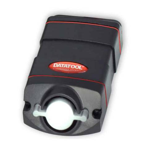
Nylon outer casing, with metal end cone protecting the siren. The housing contains the PCB which is fully potted, so
protecting the PCB itself from; attack, water ingress and component failure through vibration.
Each product can easily be distinguished by the colour of seals between the alarm sections as follows:
S4 C1 Red (Category 1) has RED Seals
S4 C221 Green (Category 2-1) has GREEN Seals
S4 C4 Yellow (Category 4) has YELLOW Seals
For ease of description from this point on each alarm will be distinguished by its coloured gaskets (e.g. the Cat 4 product
is the S4 Yellow)
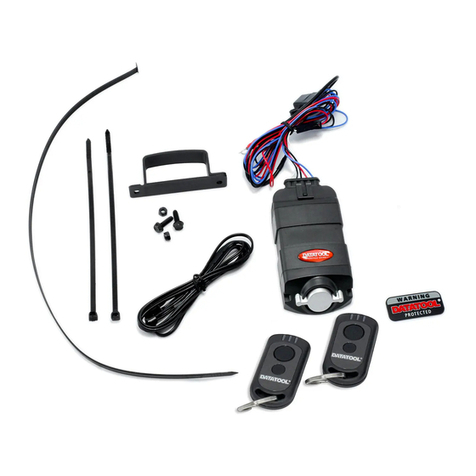
The all black wiring harness exits the unit and is terminated at set of multi-plugs 20cm from the alarm. A 2m black
harness with coloured tags on the end connects to this plug. The inter-connection is protected by a metal security
housing. This housing must be installed to comply with insurance criteria.
2 remotes are provided as standard on all products. The remotes are anti-scan, anti grab with 226 Code combinations.
The remotes for the S4 Red and Green products can be combined with the OE ignition key and OE transponder system if
required.
The S4 Yellow ‘moon’ transmitters have identical coding protocols to the Red/Green transmitter types.
Should a customer wish to combine their ignition key with the remote when they have purchased a Yellow product, all
they need to do is purchase and code in one of the Red/Green type transmitters.
All S4 units contain a Trovan® transponder tag which enables the unit to be scanned to establish identity/ownership.
S4 Housing S4 Red and Green Transmitters S4 Yellow Transmitters
Overall size (Max housing dimensions, excluding bracket)
Length 111.7mm Width 60.2mm Height 33.7mm
S4 series current consumption
Average current (sampling 10mins ) Voltage
S4 Red and Green S4 Yellow
Disarm 2.85mA 2.09mA 12.0 V
IGN ON 118.2mA 53.5mA 12.0 V
Arm 2.897mA 2.14mA 12.0 V
Sleep mode level 1 2.233mA 1.41mA 11.5 V
Sleep mode level 2 2.218mA 1.40mA 10.5 V
Sleep mode level 3 2.216mA 1.39mA 9.8 V
Winter mode 131µA 131 µA 12.0 V
Important: Please read page 47 of this manual BEFORE carrying out any current
testing.

4
Specifying the system
There are 3 different models within the S4 range. All are Thatcham approved at varying levels. If the security system is
being installed to meet an insurance requirement, it is critical the correct alarm system is chosen. If a unit is installed
which is of a lower standard than required, the only solution is to de-install and fit the correct unit. Datatool (UK) Ltd
cannot be held responsible for incorrect choice of product for any installation.
If you are unsure of the unit required please refer to the Thatcham website www.thatcham.org for the latest listings of
The table below sets out the main requirements when selecting the required unit, along with the Thatcham approval
number. It is possible to fit a unit of a higher standard than the minimum required without adverse effect on both the
operation of the unit and insurance premium.
Should you fit a S4 Red without the immobilisation wires connected (i.e. as an S4 Green spec), the Thatcham approval
number for the alarm MUST be quoted as per the S4 Green (i.e. TMCU-203/1104). If the number is quoted as a full cat 1
alarm it is being misrepresented and may void the customer’s insurance against theft. This applies to the Yamaha and
Honda model specific harnesses too.
All Thatcham listed systems (including model specific plug-in systems) MUST be fitted by an approved Datatool Dealer
only. Due to safety issues, Datatool (UK) Ltd reserve the right to withdraw supply to any dealer found to be supplying
Thatcham listed alarm/immobilisers without fitting.
If the customer does not require an insurance approved system the Datatool Compact 2 (Pt. No. 02000030) or Scooter
alarm (Pt. No. 02000033) can be installed instead. These units can be sold as supply only for the customer to fit
themselves.
Should the customer wish to have only an immobiliser installed, Datatool provide two Thatcham approved products:
The UNO suitable for machines of up to 125 ccs only (Pt. No. 02000020)
The DUO suitable for ALL machines (Pt.No. 02000010)
Both these immobiliser products are Thatcham approved and MUST be installed by an approved Datatool dealer only.
Thatcham approval numbers
Description Thatcham category Thatcham (MIRRC) number
S4 C1 Red Alarm/Immobiliser
(All machines) Cat 1 TMC1-202/1104
S4 C221 Green Alarm upgrade
(For machines already Thatcham
category 2 approved)
Cat 2-1 TMCU-203/1104
S4 C4 Yellow Alarm/Immobiliser
(Up to 125cc only) Cat 4 TMC4-204/1104
Uno Single circuit touch key
immobiliser
(Up to 125 cc only)
Cat 4 TMC4-011/0899
Duo Twin circuit touch key
immobiliser
(All machines)
Cat 2 TMC2-05/0899
Customer decisions
An Alarm/Accessory selection sheet can be downloaded from the Dealer section of the Datatool website
www.datatool.co.uk. This sheet is designed to assist in getting the combination of alarm, accessories and settings correct
for the customer when discussing the installation of their security system.
Due to the design of the S4 series it is possible to configure the system in several ways. It is wise to discuss the options
available with the customer when discussing the system. Some of the features may not be applicable to certain markets
due to local regulations (e.g. panic).
First select the type of security system the customer requires and then discuss any special requirements the customer
may have (e.g. LED position, extra siren, secondary trigger line, key conversion, full passive arming, etc).
The recorded information will reduce the chances of installation errors and assist the person fitting the system. If there is
any doubt regarding a technicality of installation, it is wise to discuss the proposal with the installing technician or
Datatool.

5
Several of the customer decisions may affect the final fitted price of the system. The sheet offers an opportunity to
itemise these so the customer is aware of their options and the costs involved. The actual charge for each service is not
controlled by Datatool (UK) Ltd and can be used by each dealer to act as a profit maker or sales incentive.
A very simple upgrade of the S4 system is by the addition of the Datatool S4 tagging upgrade kit (Pt. No. 02000127). This
kit is very specific and must only be sold to customers who are purchasing an S4 insurance approved system. It can be
sold either for self fit or for fit during alarm installation along with any installation charge. An alternative tagging kit, Gold
standard (Pt. No. 02000126) is available for customers who have not selected an S4 based security system. Both the
above kits are Thatcham recognised.
The key conversion is again a good sales incentive/additional profit point. Both keys can be converted if required. If the
ignition key contains an OE Transponder chip, the conversion is a little more involved and should be charged for
accordingly. Details of most conversions can be viewed on www.datatool.co.uk
The Datatool Website (www.datatool.co.uk)
The Datatool website contains information covering the installation of systems to many of the more popular machines.
The access to the dealer section of this website is restricted to Datatool approved dealers only. This is password
protected to each dealer individually.
If you do not have access to the website please contact your area sales manager.
Please note: Any dealer found to be passing information to non-approved third parties will immediately have their
access to the website removed and may have their account closed.
The machine information contained within the website covers the following:
Best position for the alarm
Best position for the LED
Best position for the alarm ECU protection switch
A list of the parts required to be removed for installation, in order
The colour and location of the wires used for alarm installation
Any special notes covering important issues on the machine
The machine information section of website also contains details for the installation of other Datatool products.
In certain cases photos are available to aid the installation.
Due to the settings on certain computers, you may find occasions where some of the information is lost from one side of
the sheet when you print it out. If you find this happening, change the paper settings to print the page landscape
If no information for the machine you are working from is on the website some guidance may still be available from
Datatool (UK) Ltd either by phone or e-mail.
If you carry out an installation where no information is available, please forward information you obtain to Datatool (UK)
Ltd either by fax (0870 165 2420) or e-mail ([email protected]). A blank version of the information sheet is available on
the Datatool website. Any information forwarded to Datatool will not be published to website until independently verified.
If Datatool forward any such information on, you will be advised it has not been verified and asked to confirm its accuracy
as part of the proving process.
Please note: Machine manufacturers can change details of their machine construction, wiring harness, etc without
prior warning. It is important all information downloaded from the website is checked prior to
installation. Whilst every effort has been made to check the information on its website, Datatool (UK)
Ltd accepts no liability for possible damage to the machine from its use.
Pre-installation checks
•Never install an alarm to a machine you have not checked out electrically and heard running.
•Always carry out a full visual inspection of the machine prior to installation, particularly if the machine is second
hand or has been brought in for an alarm to be installed. Any faults discovered should be reported to the owner
or their agent prior to carrying out the installation of the system. A pre/post installation check sheet is
available as a printable sheet in the dealer section of the Datatool website.
•The battery for the machine should be checked for full charge prior to installation. If it is found to be low it is
advisable to place it on charge. The Datatool battery condition will bring the battery up to full charge safely in
the minimum time. Should the battery be in a poor state, it is strongly advised the customer is informed the
battery needs replacement.

6
Stripping the machine
As stated above, the Datatool website carries information for many machines on parts removal for alarm installation.
Always take extreme care when removing and storing panels from the machine to ensure they do not get damaged.
Always note the size, type and position of any fixing you remove. It is very easy to forget what goes where.
Should a panel prove difficult to remove, take a further look to ensure the strip sequence is correct and that all fixing
devices have been removed (it’s very easy to miss that little hidden clip).
Planning the installation
The machine information from the website, along with the alarm/accessory sheet, will help to provide information on
where the unit is best mounted along with any specific customer requirements. These should be used as a guide.
Always plan the physical position for all the alarm components prior to installation. If there is any doubt on panel fit,
ALWAYS temporarily mount the unit and refit the panel prior to wiring the alarm. Once the alarm has been installed it may
be impossible to move the position to a new location. A few moments spent checking at this point can save several hours
of re-working. When selecting the alarm position do not forget the connector block protection housing.
Cable tie mounting technique
Well nut mounting technique
Where possible always use the bracket assembly supplied with the kit, but if this is not possible
alternative methods such as cable ties, double sided tape, heavy duty velcro, etc can be used.

7
Led mounting methods and positions
Where possible the position of the system LED should be agreed with the owner, prior to installing.
Method 1.
Method 2
.
Warning: When fitting into an LED tail light take care not to damage LED PCB
Method 3.
The alarm components should be located to ensure the maximum time is required for the thief to access the system.
Other factors such as the storage of customer’s personal belongings and other equipment such as intercoms, chain oilers,
etc should also be considered.
Only when the main unit positions have been established, should the wiring be investigated.
Planning the wiring

8
Where applicable, the method of immobilisation for the machine should be selected and the wiring configured accordingly.
The methods available are shown in annex 4 at the rear of this manual.
Access the wiring harness at the most suitable place(s) and identify the wires you are going to connect to using suitable
safe test equipment.
Analogue meters and bulb based test lights are LOW resistance and can easily damage delicate electronic units fitted to
some machines.
It is advisable to use HIGH resistance test equipment (e.g. Digital multi-meters, LED based test lights {logic probes}, LCD
testers).
If you have doubts regarding the suitability of your test equipment, please refer to the manufacturer’s workshop manual.
Once the alarm wiring points have been selected, construct the alarm harness accordingly. When constructing the alarm
loom pay close attention to the positioning of the alarm plugs in relation to each other. It is advisable to temporarily
connect the alarm harness to the alarm at this stage to correctly align and tape or heat shrink the harness together whilst
constructing the harness. Failure to do this may mean the plugs cannot be easily connected between the alarm and the
harness. Please notice the alignment of the plugs in the diagram below, the harness should be constructed so the FLAT
sides of the plugs are placed together (i.e. clasps outwards).
Alarm plugs and harness
disconnected Alarm plugs connected Alarm plugs connected and loom
taped or heat shrunk to lock the plug
positions
When routing the alarm harness it is wise to run it alongside or within the original wiring harness of the machine and
loom/sleeve it in a similar manner to the original harness where possible. The loom must be protected from any sharp
edges likely to cause damage to the harness.
Once the positions have been fixed, the alarm loom should be disconnected from the alarm and transferred to the
installation test box.
Always use the installation test box to further verify the connection. It is good practice to carry out a stage and then test
that stage via the test box before going to the next.
Connection methods
Soldered joints are recommended for all wiring connections, protected by a suitable insulation technique (heat shrink or
good quality insulation tape, correctly applied). Where connectors are used, they must be to at least the same standard
as the machine’s original equipment. Insulation displacement connectors (Scotchloks) must not be used under any
circumstances.
If a wire is not being used (e.g. secondary trigger, siren wire, etc) but may be required at some future date, the wire
should be fully insulated with its tags visible and secured safely at a convenient position. The position should be noted on
the certificate of installation.
Wires not required/not needed in the future are best removed from the harness completely or cut and correctly insulated.

9
The S4 Installation Tester
Whilst it is possible to install the S4 series of alarms without the use of the test box, it is strongly recommended
it is used on EVERY installation in order to minimise the risk of mistakes being made.
The following sections on installation have been written assuming the tester is being used.
The harness on the test box is fully coloured according to the tag colours of the alarm harness
General instructions
This test box is designed to ensure the alarm harness has been installed correctly prior to the final connection
of the alarm ECU to the installed alarm harness.
It is designed as an aid to installation and it is recommended it is used each time an alarm is installed.
By following the instructions and using the tester throughout the installation each section can be checked before
proceeding to the next. By adopting this approach the installation will be quicker as any mistake made will be
pinpointed immediately it occurs, hence reducing expensive rectification time.
The order of installation has been chosen to make each step a logical move to completion of the fitting.
It is advised the appropriate tests are carried out at the end of each stage.
The in-built protection devices within the installation tester are designed to minimise potential damage to the
machine during installation. However they are not a guarantee and so care should still be exercised to ensure
each connection being made is correct.
Do not use this test equipment with any other type of security system.
The tester can also be used in the diagnosis of faults where a machine has been returned with a suspected
alarm related fault by testing the machine and alarm wiring harness for faults.
For the test box to work the machine’s battery must be fully charged and connected. The box itself does not
provide any power
This tester is not designed to test the alarm ECU itself. Any alarm ECU with a suspected fault should be
returned to Datatool (UK) Ltd for testing but only after contacting Datatool (UK) Ltd for a warranty returns
number.
Failure to use the testing unit may result in damage to the security system or motorcycle and could result in the
warranty being void.
All the wires of the S4 series of alarms are BLACK. The colours below relate to the colour of the tags towards the end of
the wires. For ease of explanation the wiring descriptions below are grouped as per the recommended order for
connection. The description applies to all S4 series units unless stated.
The test box harness is colour coded and each colour matches the same wire tag of the harness (i.e. The Red wire of the
test box is in the same PIN position as the Red tagged wire of the alarm harness).
Full explanations of the wire functions along with hints and tips are contained within the section ‘What the wires do’.
A schematic diagram for the alarm system wiring is at the end of this training manual See Annex 5.

10
Using the installation tester.
The following section covers the basic actions to be carried out and the test to be conducted after the connections have
been made.
It describes the result you should get.
If you don’t get this result it then describes the probable cause and how to identify/cure the ‘fault’.
In certain cases it carries on to describe further testing you should carry out to finally confirm the connection you have
made is correct or further actions you may need to do to deal with secondary issues.
1. Main positive and negative connections (2 Black and 1 Red tagged wires)(Only 1 black wire on the S4 Green)
Connect the Red tagged wire to a permanent 12 volt positive supply (not directly to the battery) via a 10 amp rated fuse
(either OE or via the fuse supplied in the kit).
Connect the 2 Main black tagged wires to 2 independent earth points (only 1 wire on the S4 Green).
On the S4 Red and Yellow units BOTH LEDs Neg 1 and Neg 2 will be lit if correctly connected.
On the S4 Green only Neg 2 will be lit. This product only requires a single earth due to no immobilisation.
On the S4 Red and Yellow if only 1 LED is lit, check the connections of both earth wires and correct the connection.
If no LED’s are Lit check:
•The test box is correctly connected to the harness
•The fuse supplying the Red tagged wire is not blown
•The main fuse of the machine is not blown
•The battery of the machine is connected correctly and charged
•The machine’s main earth wire is correctly connected
•The earths used for the alarm are true earths using suitable test equipment
A further test should now be carried out. Turn on the ignition whilst watching the LED’s on the test box. They should
remain lit.
Next try all the electrical circuits on the machine whilst watching the LED’s on the test box. Again the LED’s should
remain lit.
If during these tests, one or both of the LED’s go out or any fuse blows on the machine or alarm supply, it is likely one or
both of the earth wires chosen for the alarm are not correct. Test these wires again and correct the connections.
2. The Starter cut (2 x Yellow tagged wires) (S4 Red only)
Cut the wire controlling the starter solenoid and rejoin it via the 2 Yellow tagged wires
Once connected, turn on the ignition and try to start the machine via the electric start (remember any interlocks the
machine may have e.g. Clutch, Side stand, Neutral, Brake, etc). The machine should crank over normally. If it does not
recheck:
•All the connections, including the alarm plug,
•All the machine’s fuses.
•Any possible further faults with the machine (e.g. faulty interlock switch/relay, starter button, etc).
•The test box itself (this should be checked by temporarily bridging the circuit directly)
Correct any fault found.
Now repeat the test but this time, press the STARTER CUT switch on the test box. The machine should not crank.
If it does, you have chosen the wrong wire to immobilise the starter with. Re-make the wire you have used and then find
the correct wire to immobilise the starter with and connect to this instead.
N.B. The Starter cut button will not work if there is no power to the test box, always check the LEDs, Neg
1and Neg 2 are lit

11
3. The Engine cut (White and White/Green, DC cut) or (White and White/Red, AC cut)(S4 Red and Yellow only)
Identify the method of immobilisation being used, either DC ignition (wire cut to immobilise) or AC ignition (wire earthed to
immobilise) and connect as below. For the techniques, see the annex 4 ‘immobilisation methods’ at the end of this
manual. Whichever method is chosen, the spare wire should either be removed from the harness or cut and insulated.
DC Cut method (White and White/Green wires)
Cut the wire chosen to immobilise the machine and rejoin via the White and White/Green tagged wires.
AC Earth out method (White and White/Red wires)
Connect either the White or White/Red wire to a suitable good earth supply and the remaining wire to the engine kill wire.
Testing the immobilisation
Start the machine and press the ENGINE CUT button on the test box. The machine should stop.
(N.B. If the side stand switch has been chosen to immobilise the machine it may not cut out until the machine is placed in
gear)
If the machine does not start, first check the controls of the machine (Kill switch, Fuel tap, Fall over sensor, Neutral, etc).
Also check to ensure you have re-plugged anything into the machine you may have disconnected during installation (e.g.
the ignition pack). Finally check the connections of the immobiliser and the method employed for immobilising the
machine.
If the machine fails to stop when the engine cut switch is pressed on the test box, check the connections for the
immobilisation circuit and the method/wire chosen to immobilise the machine is correct (don’t forget the relationship
between the Side stand and Neutral)
N.B. The Starter cut button will not work if there is no power to the test box, always check the LEDs, Neg
1and Neg 2 are lit
4. The 12 volt positive ignition switched supply (Brown tagged wire)(All S4 models)
Connect the Brown tagged wire to an ignition switched positive wire. Ideally this wire should be run critical and not kill
switch controlled. Turn the ignition on.
If this wire is correct the IGNITION light on the test box will illuminate.
If the light is on before the ignition is turned on, the wire you have selected a permanent 12 volt positive to connect to.
Change the connection point to an ignition controlled supply.
With the ignition still on try the machine’s electrical controls (particularly the starter) whist watching the ignition light on the
test box. The ignition light on the test box must remain lit at all times. If it goes out, change the connection supply.
Turn the ignition OFF and the ignition light on the test box should go out.
N.B. Whilst checking the ignition supply it is important to also press both the STARTER cut button and the
ENGINE cut buttons on the test box. If the Ignition light goes out the brown tagged wire has been connected to
the wrong side of an immobilised circuit and MUST be moved, or the alarm will not commission when connected
to the S4 system and the ignition turned ON.
If the alarm does not commission when the ignition is turned on at the final testing phase the above problem is
the most likely cause.

12
5. The Indicator connections (2 x Pink tagged wires)(All S4 models)
Connect one pink wire to the machine’s left indicator circuit and the other to the right.
•With the indicators of the machine cancelled and the ignition turned off; press the INDICATOR switch on the
test box. If all is correct the indicators on the machine will light (please note: On some Canbus based machines
only the front or rear indicators will light due to the design of the machines electrical system).
•If only one side lights, check the wire you have connected to on the non-lit side IS the indicator wire. Check the
connection to that side to ensure it is good.
•If neither indicator works, check you have power to the test box (Neg LED(s) ON) and both connections of the
Pink tagged wires.
•If the alarm fuse blows when you press the indicator switch or the test box buzzes or trips out, you have
connected the Pink tagged wire of the alarm to the negative wire of one or both of the indicators (or have a
direct short to the indicator wire). Re-test the indicator wires on the machine and correct the connection. Then
re-test the alarm wiring again using the test box after replacing any blown fuses.
The Indicator diode test.
Some machines require an in-line diode to be installed into the wiring of the indicator relay. To test if this is required,
carry out the following test.
•With the ignition turned OFF, position the indicator switch of the machine so it would be set to flash the
indicators either Right or Left. It doesn’t matter which way.
•Position the light switch of the machine (if fitted) so the lights would be ON if the machine was running.
•Press and hold the Indicator switch on the test box whilst looking at the dash lights and instruments to see if
anything other than the indicator repeater lights works. If this happens with the indicator set to left or right; a
diode is required.
•With the indicator switch on the test box still held ON, check to see if the headlight or side light circuit is on.
•Test the starter button to see if the machine cranks (always check the machine is in neutral and any interlock
systems on the machine are set to the run position, e.g. Kill switch, Clutch, Side stand, etc).
•If during these tests any extra lights or instruments operate, the alarm fuse blows, the test box trips out or
buzzes or the machine cranks over (and possibly starts too!) a diode will have to be inserted in line with the
input or output of the indicator relay.
Please refer to the diagram on Page 18 ‘Dioding the indicator relay’ for the method.
6. ECU Protection switch (Green/Black and Green/Red wires)(S4 Red and Green, option on Yellow)
After selecting the position and mounting the magnetic reed switch and its magnet trigger, connect the Green/Black wire
and Green/Red alarm wires one to each wire of the switch.
To test the switch:
•Replace the panel with the magnet assembly attached. The LED ‘Trigger 1’ should light up.
•Next remove the panel. The LED ‘Trigger 1’ should go out
If the LED does not come on when the panel is in position, it is probable the magnet is too far from the switch assembly or
you have a bad connection. Adjust the Switch/Magnet as required.
If the LED remains on when the panel is removed it is likely the Green/Red tagged wire is earthed somewhere along its
length, check the wiring.
7. The OPTIONAL Secondary trigger circuit (Green tagged wire)(S4 Red and Green)
Should you decide to use this wire connect it to whatever negative signal switching device you have decided to use such
as the side stand or clutch switch (remember some switches may require an in-line diode to be used).
Operate the switching device whilst looking at the ‘Trigger 2’ LED. If it is working correctly you should see it go to the
opposite state of OFF or ON during the operation, it doesn’t matter which way it switches.
If it stays ON all the time you either need to fit a diode, you have selected the wrong wire or the trigger wire is shorted to
earth. Disconnect the wire and test it by manually earthing it out whilst looking at the test box. Once checked for correct
operation, modify the connection point or fit a diode into the correct point of the trigger line.
If it stays OFF all the time you either have a bad connection or again you have selected the wrong wire. Disconnect the
wire and test it by manually earthing it out whilst looking at the test box.

13
8. The System LED connections (Orange and Grey tagged wires)(All S4 units)
Connect the Grey and Orange wires to the same colour wires of the LED either by a soldered connection or suitable
connectors, as suits the installation.
Press the LED switch on the test box to ON. Look at the installed alarm LED; it should light when the switch is ON.
If it does not light it is possible you have connected the LED in reverse. Correct this and test again.
If it still does not light check the connections to the test box and test again.
Finally if it still does not light replace the LED and test again.
9. The OPTIONAL supplementary siren output, max 500mA (Green/Yellow tagged wire)(All S4 units)
Connect the wire to any extra devices you may have fitted (e.g. supplementary siren, pager, texting unit, etc)
Press the extra siren button on the test box. The device should work when the button is pressed.
If it does not:
•Check both the power LED’s of the test box are lit. The alarm fuse may have been overloaded and blown.
•Check the connection of the Green/Yellow wire to the supplementary device.
•Check the supplementary device is triggered by a POSITIVE not a NEGATIVE and that you have wired it
correctly and fully understand how it works.
•Check the connections to the test box.
•Test you are getting a positive output from the test box on the Green/Yellow tagged wire by testing it with a
suitable test light/meter.
•If all the above is correct the fault is somewhere in the other wiring going to the supplementary device or the
device itself. Re-read the instructions for the device and correct the fault then re-test or replace as required.
Transferring the wiring and commissioning the alarm
Once the wiring harness has been fitted to the machine and fully tested by the installation tester. Disconnect the tester
and plug the alarm system onto the alarm harness.
The alarm is shipped in ‘Winter’ mode, so nothing will happen until the ignition is turned ON.
To commission the alarm, turn the ignition on and the system will start to beep with an increasing rate for 5 seconds.
After 5 seconds the alarm will sound unless disarmed by pressing the Grey button of the remote control.
On the S4 Yellow turn the ignition On then Off to wake up the system
The alarm should now be fully tested by following the operating instructions.
If any adjustments are to be made to the ways the system is to operate (e.g. adjust the movement sensor) a PIN will have
to be taught to the alarm. 1111 is the easiest to programme (follow the operating instructions).
Make the required adjustments and always advise the customer for security to set their own PIN. This can be simply
carried out by over-writing the existing PIN with the new one (any previous PIN will be deleted).
Only when you are fully satisfied the system is working correctly, fit the metal security as shown in the diagram below.
Rebuild the machine and carry out a post installation check to ensure the machine is still working correctly and no
damage has occurred during the installation.

14
What the wires do
Main positive and negative connections
N.B. All S4 alarm systems are designed to work on 12 volt NEGATIVE earth machine. Do not install this
product to a POSITIVE earth machine.
The main positive and negative connections are the most important wires of any alarm system as they supply the power
to make most of the other functions work.
MAIN POSITIVE SUPPLY (Red tagged wire)
Many machines are now provided with a dedicated 12 volt positive feed designed to power the alarm system. Alternatives
can be the fuel injection fuse, clock or fan fuse. The rating of this fuse should be between 10 and 20 amps. If the rating
is below this the fuse may blow when indicators flash via the alarm system. It is normally safe to increase the rating of
this OE fuse by a small margin (e.g. 7.5 amps to 10amps).
The alarm is equipped with internal protection to deal with shorts on the indicators but it is always advisable to fit a
protection fuse as this protects the wiring from the fuse to the alarm unit itself. Where possible the fuse should be fitted as
close as possible to the source of power. The supply should never be taken directly from the battery.
MAIN NEGATIVE SUPPLIES (Black tagged Wires)
The S4 Red and Yellow systems have 2 earth wires due to them being equipped with immobilisation. The S4 Green unit
only has one. This is for immobilisation safety, as the alarm system would have to lose both earths before there was a
potential problem with the immobilisation. For the same reason it is very important these two wires are connected to two
separate points on the machine.
These points can be on the frame or within the wiring harness but should never be mixed and never taken directly to the
battery. Any harness based earth should be tested to ensure it is a true earth and does not change when the ignition is
turned on and switches are operated. If unsure refer to the machine’s wiring diagram.
We advise the use of harness based earths in most cases. Frame earths, especially on anodised frames, can be very
poor.
Immobilisation
The Starter cut (Yellow tagged wires)
Identify the wire which controls the starter relay (maximum load 7 amps) and cut it. Where possible remove a section of
the original cable and rejoin this wire via the 2 Yellow tagged wires of the alarm harness (one to the starter relay end and
one to the main harness end). These wires are non-directional so it doesn’t matter which Yellow wire is connected to the
relay end or the harness end.
Under no circumstances should the heavy duty wire which powers the Starter motor itself be cut.
On most machines the starter trigger will be a Positive when the ignition is turned on and the Starter button is pressed,
however this is not always the case. Many scooters and nearly all Yamaha motorcycles control the starter relay via a
Negative signal when the starter button is pressed.
The alarm system is not sensitive to whether a positive or negative is cut.
Important note: Canbus based machines It is recommended on canbus based machines that the starter
immobilisation is taken between the starter button and the ECU. If the cut is made post ECU the machine will log a fault.

15
The Engine cut(White and White/Red or White and White/Green wires)
There are two main means of immobilising a machine, the first and most common is by cutting a wire which is essential to
the running of the machine (DC cut method), the second is by earthing out a signal wire so the ignition system cannot
create the spark needed for the engine to run (AC ‘earth out’ method). Which ever method is used the immobilisation
point should be made as inaccessible as possible. One immobiliser wire will always be unused depending on the method
of immobilisation. The spare wire should be removed from the alarm/immobiliser harness.
DC Method
Identify a wire which is critical to the engine operating but which is carrying less than 7 amps and cut it. With modern
machines it is normally wise to use either the dedicated immobilisation points provided by the manufacturer or to use an
engine safety interlock (e.g. Side stand switch, Kill switch, Fall over sensor, etc). Other circuits, such as the fuel pump
relay, ignition pack, coils, etc, may be used but refer to the manufacturers manual before using these circuits as they may
cause the machine to log running faults.
Where possible remove a section of the original cable and rejoin this wire via the White and White/Green wire. These
wires are non-directional so it doesn’t matter which wire of the alarm is connected to which end of the cut wire.
Important notice: Canbus based machines It is recommended on canbus based machines that the only circuit cut
is the wire between the kill switch and the ECU. Other points of immobilisation are likely to create fault codes. Most
Canbus based machines are equipped with a transponder immobiliser as standard.
Critical notice: Transponder immobilisers/Thatcham approval More machines are now being equipped with
transponder immobilisers as standard. However many of these machines are not Thatcham approved to category 2
standards.
When selecting whether a machine can be equipped with an S4 red (alarm/immobiliser) or S4 Green (alarm upgrade) this
MUST be taken into account. The S4 Green product only gives insurance benefits if fitted onto a machine already
complying with category 2 immobilisation. Please visit www.thatcham.org for the latest listings or contact Datatool.
The wire to be immobilised is cut and rejoined via the White and White/Green wires.
The White/Red wire is not used.
Cut and insulate the White/Red wire
or remove it from the harness
Wire being immobilised
is cut
Alarm
Harness
Connect the White/Green wire to
one side of the wire which has been
cut to immobilise the machine
Connect the White wire to the other
side of the wire which has been cut
to immobilise the machine

16
AC Method
Identify the wire which when earthed out stops the ignition pack creating a spark. This wire normally runs from the Ignition
switch and/or Kill switch to the ignition pack and will have an earth on it when the machine is not running and be isolated,
have a minimal earth on it or be pulsing when the machine is running.
Connect either the White or White/Red wire to a suitable good earth supply and the remaining wire to the engine kill wire.
When the immobiliser circuit is armed the engine kill wire will be earthed out via the immobiliser circuit and hence will not
run.
Please note: Whilst this method of immobilisation works it is not as secure as the DC immobilisation above. Datatool
recommend the DC immobilisation method is used where possible (even on AC type machines).
A C Immobilisation
The wire being immobilised is ‘earthed out’ to stop the machine running.
The White tagged wire of the alarm is connected to earth.
The White/Red tagged wire is connected to the wire being immobilised.
The White/Green wire is not used
Wire being immobilised
is not cut
Alarm
Harness
Cut and insulate the White/Green
wire or remove it from the harness
Connect white
wire to earth
Connect White/Red wire to
the wire being immobilised

17
The 12 volt positive ignition switched supply(Brown tagged wire)
This wire stops the alarm from arming when the ignition is turned ON. It also is used to pull the immobilisation relay
contact together when the system is disarmed and the ignition is ON.
It is important the wire remains positive when all the machines controls are operated. Should the power fall away from
this wire the machine will cut out. For this reason we advise you connect to an ignition switched positive supply which is
run critical. In this way if the power to this wire fails the machine would stop anyway and therefore supply taken becomes
as safe as the machine itself.
One exception to this is using a kill switched controlled ignition supply. Should this supply be used it is O.K. but it must be
explained to the customer that the immobiliser will arm if the kill switch is turned to OFF.
Many installers use other circuits (e.g. the rear brake light supply). Whilst this will work it should be realised if the fuse
blows to this circuit (possibly due to a fault on the machine itself) the machine would stop and as the OE fuse blown is not
related to the running of the machine in the standard form the customer may not find it easily.
On some machines many of the ignition switched positive circuits turn off whilst the starter button is being operated to
reduce the load on the battery. This is particularly true of lighting circuits. Therefore it is extra important the 12v Ign LED
on the test box is checked to ensure it does not go out whilst cranking. If everything works fine through the test box but
when you connect the alarm the machine fails to start, this is the probable cause.
Should you choose to combine your ignition switched supply with the immobilisation of the machine it again is important
you observe the 12v Ign LED remains lit when you press the STARTER and ENGINE cut buttons of the test box. If it
goes out, then the Brown tagged wire has been connected to the wrong side of the immobilised wire and MUST be moved
or the machine will not start when connected to the alarm and the alarm will not commission.
On certain machines if you choose a different ignition switched supply to the one recommended by Datatool (e.g. Aprilia
canbus based models) there may be a few seconds delay before the lit goes out. This is quite normal on this type of
machine and simply delays the arming period of the alarm by the time it takes for the ignition control relay of the machine
to reset. If the machine has this feature most manufacturers recommend the ignition is not turned back on until after the
ignition has automatically reset. With these types of electrical systems, turning the ignition OFF and then immediately
back ON may, in extreme circumstances, cause faults on the machine. If you are unsure please refer to the
manufacturer’s manuals.
However if the 12v Ign LED remains lit at all times with the ignition turned off the Brown tagged wire must be moved.
Failure to do this will stop the system from operating as it will think the ignition is still turned on.

18
The Indicator connections(2 x Pink tagged wires)
The alarm system should be connected to the Left and Right indicator positive feeds. Do not connect to the negative wire
of the indicator. On some machines you may only be able to make the rear or front indicators operate without the
inclusion of extra diodes into the indicator outputs of the alarm system.
(Care: There is a third wire within the machine which will flash which ever way the indicator switch is set when the ignition
is on. This wire is the output from the indicator relay to the indicator switch and you must not connect the pink wires of the
alarm system to this).
Important note: BMW Canbus based machines. On these machines the original indicator lines to the
indicators must be cut and an in-line diode fitted into each of the original indicator wires with the banded end of the diode
towards the indicator bulb. The pink wire of the alarm must then be connected to the banded side of the diode. Failure to
do this will cause the machine to log a fault each time the alarm system is armed as the ZFE control unit of the machine
will see the pulse coming from the alarm. All 4 indicators can be connected to but a diode must be installed in each
indicator wire.
Dioding the Indicator relay
During testing you may have found the indicator relay requires an in-line diode to be installed. It is important this is done.
Omitting this may cause the alarm fuse to blow at a later date and potentially leave the customer stranded.
The diode can be fitted in either the feed to the relay from the fuse box or the output from the relay to the indicator switch,
it doesn’t matter which as long as it is connected the correct way round.
The input wire will be an ignition switched positive from the fuse box to the indicator relay. If this wire is cut the band on
the diode should face towards the relay
The output wire is the third wire within the harness, described above. This wire flashes whether the indicator switch is set
to the left or right, not just left or just right. When this wire is cut the diode is positioned with the band facing away from
the relay.
If you are unsure which way to fit the diode, cut the selected wire; hold the diode in line and with the ignition on set the
indicator to the left or right. If the indicators work normally, you have got it the right way round. If they do not, reverse the
diode and test again.
Once you have it the right way round, solder it in line and protect the joints with heat shrink or good quality tape.
Dioding the indicator relay

19
Alarm protection switch (Green/Black and Green/Red wires)
All Thatcham Cat 1 and Cat 2-1 products MUST be protected by an ECU protection switch. The kit comes supplied with a
magnetic reed switch for this purpose. Other switches such as Micro switches can be substituted for this switch, if
required.
The switching arrangement is change of state and basically the Green/Red wire is the trigger line and the Green/Black
wire is an earth supplied from the alarm. When armed if the earth is applied or removed from the Green/Red wire the
alarm will trigger.
Fit the magnetic reed switch so the alarm would be triggered by the removal of a seat or body panel before the alarm ECU
is accessed.
Choose an area where the switch and magnet can be placed in close proximity to each other. When correctly oriented
the air gap can be up to 35 mm, however mounting the switch or magnet on ferrous metal (steel) or rotating the magnet
will reduce this range. DO NOT MOUNT THE SWITCH/MAGNET ASSEMBLY WITH STEEL IN BETWEEN.
Connect the two wires of the switch, one to the Green/Red wire of the alarm and the other to the Green/Black wire of the
alarm. The switch has a self adhesive backing to assist in mounting and is also supplied with screws if this method is
preferred. If using the self adhesive system, clean and de-grease the area thoroughly prior to fitting.
Fit the magnet on the removable panel/seat adjacent to the switch using the fitting methods described above.
When correctly set; the LED should go out before the panel is removed by 50mm. The position of the switch/magnet
should be adjusted accordingly.
If more than one area is to be protected, extra magnets and switches are available through Datatool, this is a chargeable
extra. Extra magnets may also be needed if the pillion seat is used and the customer has a separate tailpiece. If several
switches are to be used they must be run in series, not parallel. This method also applies to accessory loop protection
where in-line connectors are positioned so soft luggage/accessories can be protected by running an extension wire
through them and remaking the continuous trigger circuit.
A magnetic reed switch kit is supplied with The S4 Yellow and it is advised it is installed, but the installation of this switch
is not mandatory on this model only.
Secondary trigger circuit(Green tagged wire)
The use of this wire is not mandatory when fitting a Thatcham alarm system so therefore should you decide to use it the
application can be charged to the customer if desired. Please discuss this with the customer prior to installation.
If you do not use this wire it should be positioned in a safe location with the Green tag still on and its position noted on the
certificate of installation, so it can be identified and accessed at a future date (DO NOT CUT IT OFF!).
POSSIBLE USES.
Accessory Loop (diagram below)
Side stand trigger (diagram below)
Clutch Switch trigger (see Side Stand trigger diagram)
Garage protection (garage kit part number 02012006)(diagram below)
Secondary panel/luggage protection (fitted as the alarm protection switch above)
PLEASE NOTE:
It is not possible to combine an ‘earth to trigger’ circuit with a ‘remove an earth to trigger’ on this single wire.
If a closed loop system is being used all switches must be in series.
If multiple applied earth triggers are being used they should be wired in parallel and are best separated by diodes.
This is particularly important if any machine interlock systems such as side stand switch or clutch switch are to be
incorporated. Failure to diode these interlocks away from other triggers may seriously effect safety.

20
Accessory Loop
Side Stand Trigger
Garage Protection kit (Pt. No. 02012006)
Other manuals for S4
3
Table of contents
Other Datatool Motorcycle Accessories manuals


