8VarioProtect XXL-W-2 TC | Version 1.01 | EN
Product characteristic and setting options
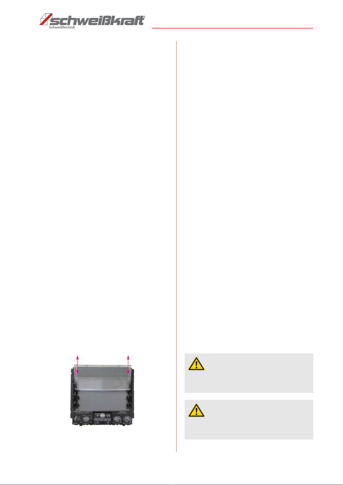
7.4 Setting the shade control
The shade ranges (from DIN4 to DIN8, or from DIN9 to
DIN13) are selected with the shade knob on the inside of
the helmet (Fig. 4).
Thanks the welding filters, the eyes and face of the wel-
der are completely protected against UV and IR radiation
during the welding work, even if the cassette does not
darken. The UV/IR protection is always up to DIN 16, so
the user is always protected against UV/IR radiation du-
ring welding.
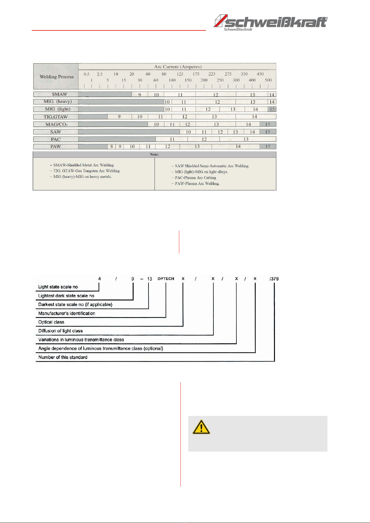
Before welding, set the shading level according to the
welding method and welding current in accordance with
the colour table (Fig. 8).
If the darkening is too strong or too slow, adjust the knob
slightly until the weld spot can be seen.
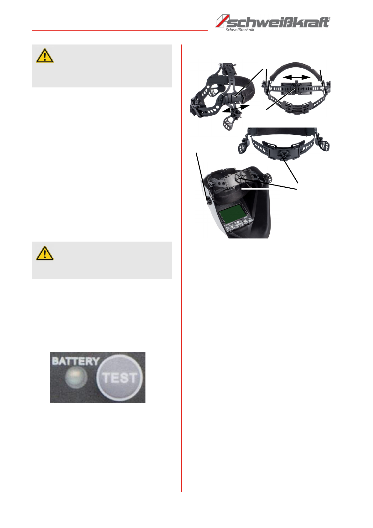
7.5 Power supply, test button
The power supply for the welding helmet is provided by a
battery.
By pressing the Test button, the charge level of the lit-
hium battery and the function of the filter can be chec-
ked.
Fig. 5: Battery test
During normal operation of the filter, after pressing the
Test button, the battery indicator lights up red and the fil-
ter darkens.
If the battery indicator does not lightening or light is very
weak, the battery must be replaced (battery type
CR2450, lithium battery).
If the battery indicator lights up and the filter does not
darken, the filter is defective and must be replaced.
7.6 Headband adjustment options
Fig. 6: Headband adjustment
1. Upper headband W (Fig. 6) - Adjustment in the direc-
tion of the arrow further or narrower to adjust the hel-
met to a suitable position.
2. Side bands Z - Adjustment option symmetrically
further or narrower in the direction of the arrow on
both sides to adjust the distance of the user's eyes to
the filter lens. To adjust, loosen the knobs on both si-
des of the helmet, move the helmet symmetrically to
the appropriate position and retighten the knobs.
3. Rear headband Y - Adjustment with knob further or
narrower to adjust the fit of the helmet looser or fir-
mer..
4. Tilt angle X - 4 adjustment options to adjust the height
of the user's eyes to the filter lens and the angle of the
helmet to the user's face. To adjust, loosen the knobs
on the outside of the helmet, move the helmet to the
appropriate position and retighten the knobs.
Due to the adjustment of the headband results in a maxi-
mum comfort.
This model is equipped with a folding mechanism (up and
down). When the welder turns the helmet towards the top of
the head, the headband mechanism makes the helmet's cen-
tre of gravity a little lower and coincides with the centre of
gravity of the welder's head.
The design of the welding helmet provides for less fatigue on
the head and neck of the welder, and thus for a more comfor-
table feeling while working.
If the headgear has been unevenly adjusted, and the di-
stance from the eyes to the filter lens is uneven, reset the
headgear to reduce the distance to the filter.
ATTENTION!
Before starting welding, it is important that the opera-
ting mode switch is set to a protection level for wel-
ding again.
ATTENTION!
If the welding helmet is used for a long time with the
wrong shading level, the eyes may be injured!