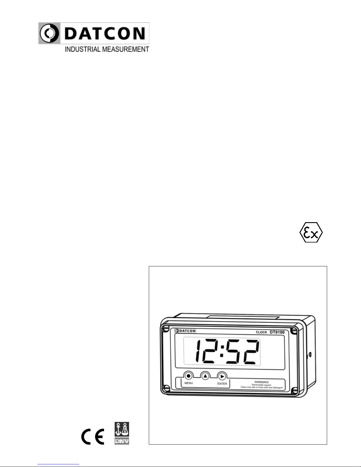
Datcon DT9100 B User manual

DT9100 B
Intrinsically Safe Digital Clock
Operating Instructions

DT9100 B
2 20140130-V0
Contents
1. About this document .....................................................4
1.1. Function ................................................................................... 4
1.2. Target group............................................................................. 4
1.3. Symbolism used....................................................................... 4
2. For your safety ...............................................................5
2.1. Authorised personnel ............................................................... 5
2.2. Appropriate use........................................................................ 5
2.3. Warning about misuse ............................................................. 5
2.4. General safety instructions....................................................... 5
2.5. CE conformity........................................................................... 5
2.6. Safety information for Ex areas................................................ 6
2.7. Environmental instructions ....................................................... 6
3. Product description .......................................................7
3.1. Delivery configuration............................................................... 7
3.2. Principle of operation ............................................................... 8
3.3. Adjustment ............................................................................... 9
3.4. Storage and transport .............................................................. 9
4. Mounting.......................................................................10
4.1. General instructions ............................................................... 10
4.2. Main dimensions of the instrument ........................................ 11
4.3. Mounting as a wall-instrument ............................................... 12
4.4. Mounting as a panel-instrument............................................. 15
5. Connecting ...................................................................17
5.1. Preparing the connection ....................................................... 17
5.2. Connecting the synchronising input ....................................... 18
5.3. Connecting the digital outputs................................................ 19
5.4. Connecting the battery pack .................................................. 20
5.5. Replace the battery pack ....................................................... 21
6. Display and manual controls ......................................23
6.1. The first start-up ..................................................................... 23
6.2. Characters and mnemonics appearing on the display ........... 24
6.3. Manual controls...................................................................... 26

DT9100 B
20140130-V0 3
7. Setting-up .....................................................................27
7.1. Typing the code (password) in ............................................... 27
7.2. The menu ............................................................................... 29
7.3. Time set (01. menu item) ....................................................... 30
7.4. Fast time set (02. menu item) ................................................ 32
7.5. User code (03. menu item)..................................................... 33
7.6. Synchronisation mode (04. menu item) ................................. 35
7.7. Synchronisation time (05. menu item).................................... 36
7.8. Synchronisation gate time (06. menu item)............................ 37
7.9. Digital output 1 (07. menu item) ............................................. 38
7.10. Digital output 2 (08. menu item) ........................................... 39
7.11. Changing the supervisor code (09. menu item) ................... 40
7.12. Tests (10. menu item) .......................................................... 42
8. Fault rectification .........................................................44
8.1. Fault finding............................................................................ 44
8.2. Repairing................................................................................ 44
9. Dismounting .................................................................44
9.1. Dismounting procedure .......................................................... 44
9.2. Disposal ................................................................................. 44
10. Appendix.....................................................................45
10.1. Technical specifications ....................................................... 45
10.2. Application example ............................................................. 47
10.3. Error messages.................................................................... 48
10.4. Messages of critical errors ................................................... 49
10.5. Description of the menu items.............................................. 50
10.6. Messages and error messages during setting up ................ 53
10.7. Time set (example) .............................................................. 54
10.8. ATEX Certification................................................................ 56

DT9100 B
4 20140130-V0
1. About this document
1.1. Function
This operating instructions manual has all the information
you need for quick set-up and safe operation of DT9100 B.
Please read this manual before you start setup.
1.2. Target group
This operating instructions manual is directed to trained
personnel. The contents of this manual should be made
available to these personnel and put into practice by them.
1.3. Symbolism used
Information, tip, note
This symbol indicates helpful additional information.
Caution, warning, danger
This symbol informs you of a dangerous situation that could
occur. Ignoring this cautionary note can impair the person
and/or the instrument.
Ex applications
This symbol indicates special instructions for Ex
applications.
•
List
The dot set in front indicates a list with no implied sequence.
→
Action
This arrow indicates a single action.
1
Sequence
Numbers set in front indicate successive steps in a
procedure.

DT9100 B
20140130-V0 5
2. For your safety
2.1. Authorised personnel
All operations described in this operating instructions
manual must be carried out only by trained and authorised
specialist personnel. For safety and warranty reasons, any
internal work on the instruments must be carried out only by
DATCON personnel.
2.2. Appropriate use
The DT9100 B is a battery-powered intrinsically safe digital
clock. Detailed information on the application range of the
DT9100 B is available in chapter „Product description”.
2.3. Warning about misuse
Inappropriate or incorrect use of the instrument can give rise
to application-specific hazards, or demage to system
components through incorrect mounting or adjustment.
2.4. General safety instructions
The DT9100 B is a high-tech instrument requiring the strict
observance of standard regulations and guidelines. The
user must take note of the safety instructions in this
operating instructions manual, the country-specific
installation standard as well as all prevailing safety
regulations and accident prevention rules.
2.5. CE conformity
The DT9100 B is in conformity with the provisions of the
following standards:
MSZ EN 61326:2000 (EMC)
MSZ EN 60079-0:2007 (ATEX)
MSZ EN 60079-11:2007 (ATEX)
MSZ EN 60079-14:2003 (ATEX)

DT9100 B
6 20140130-V0
2.6. Safety information for Ex areas
Please note the Ex-specific safety information for installation
and operation in Ex areas. These safety instructions are
part of the operating instructions manual and come with the
Ex-approved instruments.
2.7. Environmental instructions
Protection of the environment is one of our most important
duties.
Please take note of the instructions written in the following
chapters:
•Chapter 3.4. Storage and transport
•Chapter 9.2. Disposal

DT9100 B
20140130-V0 7
3. Product description
3.1. Delivery configuration
Delivered items The scope of delivery encompasses:
•DT9100 B digital clock
•DT4V5BAT power supply
•2 pcs. of srew clamps (only panel mounting version)
•2 pcs. Pg 11 cable entries
• instrument sealing (only panel mounting version)
•documentation:
this oparating instructions manual
certification
warranty
The instrument is built from the following main parts:
Main parts
1. instrument case
2. front panel with 3 mambrane push buttons

DT9100 B
8 20140130-V0
3.2. Principle of operation
Area of application DT9100 B is an intrinsically safe digital clock enable
accurate time to be displayed in even the most hazardous
plant areas: Zone 1, 2 or in the safe area.
Synchronising function allows the clock to be synchronised
with a master clock. Connecting synchronising terminals
together will stop the clock. When the terminals are
disconnected the clock will re-start from a new time selected
in the programme menu. This may be the nearest minute or
the nearest hour of the original display or a preset time may
be entered during programming.
The DT9100 B has two isolated digital outputs, which can
be used for alarm signaling or for synchronising other
clocks.
The clock is powered by a replaceable intrinsically safe
battery pack.
DT9100 B is housed in a moulded polycarbonate case
hauseproof to IP65 for installation in the field or on the
control panel.
Operating principle
The clock incorporate a high accuracy temperature
compensated time base, which is processed by a
microcontroller. The microcontroller produces the real time,
in 24 hour HH:MM format, drives the large 4 digit 25,4 mm
height LCD display, process the front panel keypad, the
synchronising inputs, and drives the digital outputs. The
settings and the actual time are stored in a memory which
stores it’s content for cca. 1 hour for bridging the battery
exchange time.
Power supply The DT9100 B is powered by the built in DT4V5BAT type
intrinsically safe replaceable battery pack, which will
operate the clock for at least two years.
The battery replacement can be accomplish even in the
hasardous area.

DT9100 B
20140130-V0 9
3.3. Adjustment
The DT9100 B can be adjusted through the 3 front panel
membrane keypad. The instrument doesn’t need any
internal adjustment.
All settings are stored in a battery back-up RAM.
At first installation you have to set the time and other
working parameters what you need.
At battery replacement the settings are kept for min. 1 hour
3.4. Storage and transport
This instrument should be stored and transport in places
whose climatic conditions are in accordance with Chapter
10.1. Technical specifications, as described under the
title: Environmental conditions.
The packaging of DT9100 B consist of enviroment-friendly,
recyclable cardboard is used to protect the instrument
against the impacts of normal stresses occurring during
transportation. The corrugated cardboard box is made from
environment-friendly, recyclable paper. The inner protective
material is polyfoam and nylon, which should be disposed of
via specialised recycling companies.

DT9100 B
10 20140130-V0
4. Mounting
4.1. General instructions
Use the enclosed seal when mounting DT9100 B on panel
to assure IP 65 protection between the instrument and the
panel from the front side (only panel mounting version).
Electrostatic hazard! Clean only a moist cloth and
detergent.
Mounting positions
Select a mounting position you can easily read the display
reach for mounting and connecting the instrument and that
minimises the hazard of water, dust or dump getting into the
instrument.
Mounting cable entries
The insrument is equipped with one PG11 cable entry and
two additional hole equipped with sealing plugs. Two PG11
cable entry is accessory. If required more than one cable
entry (see chapter 5.) put out the sealing plug turning it in
anticlockwise direction. To put in the cable entry use the
sealing turn it in clockwise direction. Tighten the screws so
much that ensures the desired sealing. Use only appropriet
tools.

DT9100 B
20140130-V0 11
4.2. Main dimensions of the instrument
Wall mounted instrument
Panel instrument

DT9100 B
12 20140130-V0
4.3. Mounting as a wall-instrument
Removing the front
cover
In order to remove the front cover, first remove the four
fixing screws as shown in the drawing. A screwdriver of
appropriate head-size only should be used. Using
screwdrivers with inappropriate head-size may cause a
damage in the screws’ heads or in the instrument front
panel.
Remove the screws by turning them in anticlockwise
direction as shown in the drawing Step (1). The screws are
secured against falling out. After this you can simply take
away the front cover from the housing (2) and you can open
it by turning it downwards (3). Plastic ties are used to fasten
the front cover to the housing, preventing it from falling.

DT9100 B
20140130-V0 13
Preparatory steps There are four through-holes, shown by arrows in the
following drawing, for the fastening of the housing. The
diameters of the holes are made for M3 screws.
Holes for mounting
1. Mark the places of the holes in accordance with the
drawing.
2. Make the holes for mounting ready.
3. Remove any burrs from the ready-made holes.
Please observe the safety rules throughout the operation.

DT9100 B
14 20140130-V0
Mounting the instrument
Four M3 threaded screws are needed for mounting the
instrument (these are not accessories). The type of the
screws depends on the wall-material, while the dimensions
depend on the wall-thickness. The use of cross recessed
pan head screws is recommended to make the mounting
easier. The minimum screw-length should be the wall-
thickness + 10 mm.
During mounting, please observe all safety rules, and use
only appropriate tools.
Secure the screws against getting loose. For this purpose
you may use spring lock or serrated lock washers.
Depending on the material of the wall, and in order to
ensure the most practicable mounting method, it is not
mandatory, of course, to use the above-described threaded
joints. Depending on the situation, special screw types for
wood or for metal sheets can also be used, or the joint can
be riveted too.
Mounting the front cover
back to its place
1. Check if there are alien materials left in the housing, like
small tools, wire or metal pieces, plastic chips, etc. If there
are, remove them.
2. Put back the front cover of the instrument, taking care
that the sealing should get to its place. There should be no
gap, nor cables caught between the housing and the front
cover.
3. Tighten the front cover.
Turn the screws in clockwise direction. Tighten the screws
so much that ensures the desired sealing.

DT9100 B
20140130-V0 15
4.4. Mounting as a panel-instrument
Preparatory steps
1. Cut-out the panel according to the figure shows below.
The cut-out needs spetial tools, it must be carried out by
trained specialist personnel.
Cut-out dimensions

DT9100 B
16 20140130-V0
Mounting by the
screw clamps
2. Put on the enclosed seal onto the instrument case from
the rear side and fit it to the instrument holding frame
(Figure step 2).
3. Put the instrument into the prepared cut-out until it
possible and check the fitting of the seal between case and
mounting surface.
4. Put on the enclosed screw clamps onto the sides of the
instrument case (Figure step 4.1, 4.2).
Fix the instrument by turning the srews in clockwise
direction (Figure step 4.3).
Pay attention not to let pointed, sharp metal parts cause
accidents.

DT9100 B
20140130-V0 17
5. Connecting
5.1. Preparing the connection
Select and prepare
connection cable
How to use the push in
direct connectors
Always observe the following safety instructions:
• When you are going to install instruments in hazardous
area or install instruments which are connecting to
instruments are working in hazardous area you should take
note of the appropriate regulations, conformity and type
approval certificates of the DT9100 B and the other
instruments (e.g. isolator, Zener barrier). The connection
must be carried out by trained and authorized personnel
only!
Take note of the corresponding installation regulations for
Ex applications. In particular, make sure that no potential
equalization currents flow over the cable screen. Ground
only one side the cable screen.
• Use only a screwdriver with appropriate head
• Do not touch to each other the wire ends of the battery
pack
Take note the suitability of the connecting cable
(wire cross-section, insulation, cable screen, etc.).
The wire cross-section should be 0.25–1.5 mm2.
You may use either solid conductor or flexible conductor.
In case of using flexible conductor use crimped wire end.
1. Remove approx. 30 mm of cable mantle, strip
approx. 8 mm insulation.
2. Remove the instrument front cover (see chapter 4.3.).
3. Loosen compression nut of the cable entry.
4. Insert the cable into the instrument through the cable
entry.
1. Push the cable-end until it possible into the terminal
assembly.
2. By pushing the wire in, the self-closing connection is
being established. Check it by pulling it outwards slightly.
(3. When you disassemble the cable, push down the white
button by a screwdriver, and pull the cable-end out.)
There is no need to use great force for pushing the cable in,
neither for removal. The button can be pushed down easily.
Please do not exercise forces higher than necessary, as it
may cause damages to the terminal assembly.

DT9100 B
18 20140130-V0
5.2. Connecting the synchronising input
A DT9100 B synchronising input is a digital input for driving
it either with a contact or with a solid state switch. You may
connect an instrument to the input which output is in
comformity with the following input paremeters:
Uo < 30 V, Io < 200 mA, Po < 0,75 W.
The following figure shows the connection:
Wiring plan, connecting
the synchrinising input
(see also “Application
example”)
Be careful the polarity of
the cables
1. Push the cable-end until it possible into the terminal
assembly. By pushing the wire in, the self-closing
connection is being established.
2. Check it by pulling it outwards slightly.

DT9100 B
20140130-V0 19
5.3. Connecting the digital outputs
A DT9100 B digital output is an output for direct driving an
other clock synchronising input or a NAMUR input.
You may connect an instrument to the output which input is
in comformity with the following output paremeters:
Uo < 10 V, Io < 200 mA, Po < 0,5 W.
The following figure shows the connection:
Wiring plan, connecting
the digital outputs
(see also “Application
example”)
Be careful the polarity of
the cables.
1. Push the cable-end until it possible into the terminal
assembly. By pushing the wire in, the self-closing
connection is being established.
2. Check it by pulling it outwards slightly.

DT9100 B
20 20140130-V0
5.4. Connecting the battery pack
The DT9100 B is powered by the built in DT4V5BAT type
intrinsically safe replaceable battery pack, which is not
connected to the clock when shipping. Before using the
battery pack should connect to the clock.
The battery connection or replacement can be accomplish
even in the hasardous area.
Do not use other battery type!
The following figure shows the connection:
Wiring plan, connecting
the battery pack
Be careful the polarity of
the cables
1. Push the cable-end until it possible into the terminal
assembly. By pushing the wire in, the self-closing
connection is being established.
2. Check it by pulling it outwards slightly.
Checking the
connections
Check if the cables are connected properly (have you
connected all the cables, have you connected to the right
place, do not the cable-ends touch each other).
Other manuals for DT9100 B
1
Table of contents
Other Datcon Clock manuals