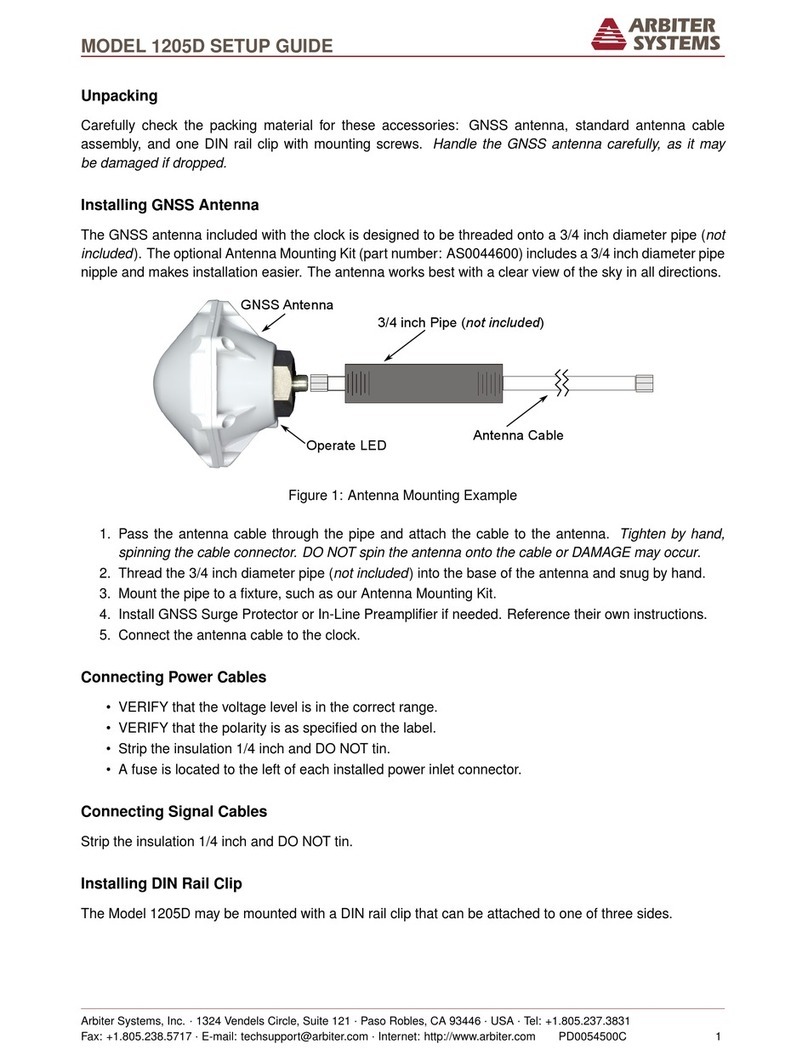
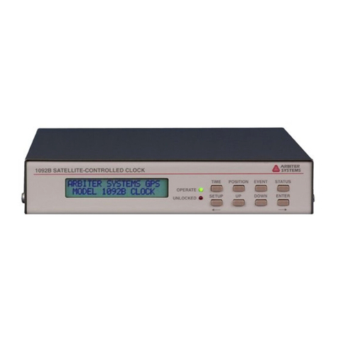
Arbiter Systems 1205B User manual

2

3
Description
This manual is issued for reference only, at the convenience of Arbiter Systems. Reasonable effort
was made to verify that all contents were accurate as of the time of publication. Check with Arbiter
Systems at the address below for any revisions made since the original date of publication.
Contact Information
Arbiter Systems, Inc.
1324 Vendels Circle, Suite 121
Paso Robles, CA 93446
USA
(805) 237-3831
www.arbiter.com
techsuppor[email protected]
What This Manual Covers
This manual describes the configuration and operation of the Model 1205B/C and the Model
1206B/C series of GNSS Synchronized Clocks. This version of the manual is written for clocks
having a firmware date that was available at the time of this publication. Any changes made in
subsequent revisions, which affect operation or specifications, will be noted with either a revised
version of the manual or a product bulletin. Todisplay the overall clock firmware version, press the
SYSTEM key (see Section 4.6.1) or use the web interface as illustrated in Section 5.3.28.
Firmware Versions & Updates
Firmware updates are available by download from the Arbiter Systems website from
www.arbiter.com. For service, contact the factory. Electronic versions of this manual are available
from the Arbiter website.

4
LIMITED WARRANTY
Arbiter Systems makes no warranty,expressed or implied, on anyproduct manufactured or sold
by Arbiter Systems except for the following limited warranty against defects in materials and
workmanship on products manufactured by Arbiter Systems.
Products manufactured by Arbiter Systems are guaranteed against defective materials and
workmanship under normal use and service from the date of delivery for a period of five (5) years.
The responsibility of Arbiter Systems under this warranty is limited to repair or replacement, at
Arbiter Systems’ option, of any product found to be defective. Arbiter Systems shall have no liability
under this warranty unless it receives written notice of any claimed defect.
For warranty service or repair, products must be returned to a service facility designated by Arbiter
Systems. Buyer shall prepay all shipping charges, duties, and taxes to send the product to Arbiter
Systems, and Buyer shall prepay shipping charges, duties, and taxes to return the product to Buyer.
THE WARRANTY SET FORTH HEREIN CONSTITUTES THE ONLY WARRANTY OBLIGA-
TIONS OF ARBITER SYSTEMS, EXPRESSED OR IMPLIED, STATUTORY, BY OPERATION OF
LAW, OR OTHERWISE. ARBITER SYSTEMS DISCLAIMS ANY WARRANTY OF MER-
CHANTABILITY OR FITNESS FOR A PARTICULAR PURPOSE, AND BUYER EXPRESSLY
WAIVES ALL OTHER WARRANTIES.
This limited warranty does not extend to any product, which has been subject to
1.
Improper use or application, abuse, or operation beyond its rated capacity, or
contrary to the instructions in the operation and maintenance manuals (if any);
2.
Accident;
3.
Repair or maintenance performed byBuyer,except in accordance with the operation
and maintenance manuals, if any,and any special instructions of Arbiter Systems;
4.
Modification without the prior written authorization of Arbiter Systems (whether by the
substitution of non-approved parts or otherwise). The remedies provided herein are
Buyer’s sole and exclusive remedies. In no event shall Arbiter Systems be liable for
direct, indirect, incidental, or consequential damages (including loss of profits), whether
based on contract, tort, or other legal theory.
FOR THE FASTEST POSSIBLE SERVICE, PLEASE PROCEED AS FOLLOWS:
1.
Notify Arbiter Systems, Inc., specifying the instrument model number and serial
number and giving full details of the difficulty. Service data or instrument-return
authorization will be provided upon receipt of this information.
2.
If instrument return is authorized, forward prepaid to the manufacturer. If it is
determined that the instrument is not covered by this warranty, an estimate will be
made before the repair work begins, if requested.

5
Model 1205B/C
Model 1206B/C
GNSS Synchronized Clock
Operation Manual
Chapter 1
Getting Started
Chapter 2
Front and Rear Panels
Chapter 3
Antennas & Cables
Chapter 4
Startup and Operation
Chapter 5
Web Interface
Chapter 6
SSH Console Interface
Chapter 7
SNMP Support
Chapter 8
NTP/PTP Server
Chapter 9
Main Input/Output (I/O) Module
Chapter 10
Optional Inputs & Outputs
Chapter 11
Functional Description & Specifications
Appendix A
Using a Surge Arrestor
Appendix B
CE Mark Certification
Appendix C
Creating a Self-Signed Certificate
Appendix D
Creating a Custom Serial Broadcast
Index
CopyrightArbiter Systems Incorporated December2022.
All rights reserved. International copyright secured.
Reorder Number: AS0100300
Printed Document: PD0051500 Rev. C

6
Table of Contents
Chapter 1 Getting Started.................................................................................................................................. 14
1.1 Overview.................................................................................................................................................... 14
1.2 Security and Performance Advantages....................................................................................................... 14
1.3 Standard Features...................................................................................................................................... 14
1.4 Standard Accessories ................................................................................................................................ 15
1.4.1 Handling Precautions .......................................................................................................................... 15
1.4.2 Unpacking and Locating Accessories................................................................................................... 15
1.4.3 Removing Rackmount Ears.................................................................................................................. 16
Chapter 2 Front and Rear Panels ...................................................................................................................... 17
2.1 Overview.................................................................................................................................................... 17
2.2 Front Panel Controls and Indicators........................................................................................................... 18
2.2.1 Command KeyDefinitions.................................................................................................................... 18
2.2.2 LED Status Indicators........................................................................................................................... 19
2.2.3 LCD Display........................................................................................................................................ 19
2.2.4 Large LED Display: Model 1205C & Model 1206C............................................................................ 19
2.2.5 USB..................................................................................................................................................... 19
2.3 Rear Panel Information............................................................................................................................... 19
2.3.1 Power Inlet.......................................................................................................................................... 20
2.4 Antenna Input............................................................................................................................................. 21
2.5 Main I/O Connector Block Functions........................................................................................................... 21
2.5.1
Specifications for Main Connector Functions
............................................................................................ 22
2.5.2 Event Input.......................................................................................................................................... 22
2.5.3 RS-232 and RS-485 Communication Ports.......................................................................................... 22
2.5.4 SPDT Relay Contacts.......................................................................................................................... 23
2.6 Optional Inputs and Outputs....................................................................................................................... 23
2.6.1 Option Module Selection...................................................................................................................... 23
2.7 Network Connections ................................................................................................................................. 24
Chapter 3 Antennas and Cables........................................................................................................................ 25
3.1 Mounting the Antenna and Antenna Cable............................................................................................... 25
3.1.1 GNSS Antenna Location...................................................................................................................... 25
3.1.2 Mounting the Antenna.......................................................................................................................... 25
3.1.3
Optional
Antenna
Mounting Kit, P/N AS0044600
................................................................................... 26
3.2 Verifying Antenna and Cable Operation...................................................................................................... 27
3.2.1 Checking the Antenna Status............................................................................................................... 27
3.3 GNSS Surge Arrester, P/N AS0094500 ...................................................................................................... 28
3.3.1 Using the GNSS Surge Arrester.......................................................................................................... 28
3.4 Technical Details of GNSS Antennas and Cables ....................................................................................... 28
3.4.1 Length and Loss Considerations.......................................................................................................... 28
3.4.2 Physical Protection .............................................................................................................................. 30
3.4.3 Adjacent Signals.................................................................................................................................. 30
3.4.4 Antenna Power.................................................................................................................................... 30
3.4.5
Connection to Antenna
................................................................................................................. 30
3.4.6 Connection to Clock............................................................................................................................. 30
3.4.7 User-Supplied Antenna Cables............................................................................................................ 30
Chapter 4 Startup and Operation....................................................................................................................... 31
4.1 InitialStartupSequence............................................................................................................................... 31
4.1.1 Display Indication at Startup ................................................................................................................ 31
4.1.2 Clock Time, Startup Mode ................................................................................................................... 31

7
4.2 Operating Modes........................................................................................................................................32
4.2.1 Learn and Normal Modes.....................................................................................................................32
4.2.2 Normal Mode Operation and Re-entry..................................................................................................32
4.2.3 Faults and Alarms ................................................................................................................................32
4.3 Time/Date Key Displays..............................................................................................................................33
4.3.1 Time and Date Display, UTC...............................................................................................................33
4.3.2 Time of Year Display, UTC...................................................................................................................33
4.3.3 Time and Date Display, Local Time.......................................................................................................33
4.3.4 Time of Year Display, Local Time..........................................................................................................33
4.3.5 Daylight Saving Time/Summer Time (DST)..........................................................................................33
4.4 Antenna Key Displays.................................................................................................................................33
4.4.1 GNSS Tracking....................................................................................................................................34
4.4.2 GNSS Signal-to-Noise Ratio.................................................................................................................34
4.4.3 GNSS Setting ......................................................................................................................................34
4.4.4 Antenna Status....................................................................................................................................34
4.4.5 Position Display Modes.........................................................................................................................34
4.4.6 Longitude Display.................................................................................................................................34
4.4.7 Latitude Display....................................................................................................................................35
4.4.8 Elevation Display..................................................................................................................................35
4.5 Timing Key Displays....................................................................................................................................35
4.5.1 Clock Status ........................................................................................................................................35
4.5.2 Time Quality ........................................................................................................................................35
4.5.3 Holdover Estimated Uncertainty............................................................................................................36
4.5.4 Spoofing Status ...................................................................................................................................36
4.5.5 Event/Deviation....................................................................................................................................36
4.5.6
Event Display
...................................................................................................................................37
4.5.7 Deviation Display..................................................................................................................................37
4.6 System Key Displays...................................................................................................................................37
4.6.1 Serial Number and Firmware Version...................................................................................................37
4.6.2 Power Supply.......................................................................................................................................37
4.6.3 EEPROM Errors...................................................................................................................................37
4.6.4 Fault Indications...................................................................................................................................38
4.6.5 Alarm Indications..................................................................................................................................39
4.6.6 Network Status ....................................................................................................................................40
4.6.7 NTP/PTP Status..................................................................................................................................40
4.6.8 Analog Input ........................................................................................................................................40
4.6.9 HD Output Current................................................................................................................................40
Chapter 5 User Interface (UI)..............................................................................................................................41
5.1 Administration.............................................................................................................................................41
5.1.1 Configure Directly ................................................................................................................................41
5.1.2 Logging in to the User Interface Directly.............................................................................................41
5.1.3 The IP Address.....................................................................................................................................42
5.1.4 Important Configuration Change Notes.................................................................................................42
5.2 Security.......................................................................................................................................................42
5.3 User Interface.............................................................................................................................................43
5.3.1 User Interface Startup Page .................................................................................................................43
5.3.2 Time/Date Settings ..............................................................................................................................44
5.3.3 User Interface Configuration.................................................................................................................45
5.3.4 Learn/Normal Modes............................................................................................................................45
5.3.5 Configure Password.............................................................................................................................46
5.3.6 Firmware Updates................................................................................................................................46
5.3.7
Reboot System
.....................................................................................................................................47
5.3.8 Configure Front PanelElements ............................................................................................................47
5.3.9 GNSS Information................................................................................................................................48
5.3.10 Antenna Information...........................................................................................................................49
5.3.11 Spoofing Information..........................................................................................................................49
5.3.12 General Clock Status..........................................................................................................................51
8
5.3.13 Configure Standard Relay.................................................................................................................. 52
5.3.14 Network Status.................................................................................................................................. 53
5.3.15 Network Configuration........................................................................................................................ 54
5.3.16 Analog Input over IP........................................................................................................................... 55
5.3.17 Serial Port Communication Settings................................................................................................... 56
5.3.18 Programmable Pulse Output Settings................................................................................................. 57
5.3.19 Open Drain, High Voltage Switching .................................................................................................. 58
5.3.20 Modulated IRIG-B.............................................................................................................................. 59
5.3.21 Optional Outputs –Slots A, B and C................................................................................................ 60
5.3.22 Event Inputs and System Frequency.................................................................................................. 61
5.3.23 Fault Status and Configuration........................................................................................................... 62
5.3.24 Configure PTPProtocols.................................................................................................................... 63
5.3.25 View PTP Status................................................................................................................................ 64
5.3.26 Configure NTP Protocols.................................................................................................................... 65
5.3.27 NTP/PTP Uncertainty Measurements Plot.......................................................................................... 66
5.3.28 Support –Contact Page and Firmware Versions............................................................................... 67
5.3.29 Support –Update Log........................................................................................................................ 68
5.3.30 Logout ............................................................................................................................................... 68
Chapter 6 SSH Console Interface...................................................................................................................... 69
6.1 Using the SSH Console Interface............................................................................................................... 69
6.1.1 Useful Keys for SSH Console Navigation........................................................................................... 70
6.2 SSH Console Menus .................................................................................................................................. 70
6.2.1 Network Status Page............................................................................................................................ 70
6.2.2 Network Configuration Page................................................................................................................. 71
6.2.3 Administration –Configure................................................................................................................... 71
6.2.4 Administration –Password................................................................................................................... 72
6.2.5 Administration –Firmware Update....................................................................................................... 72
6.2.6 Administration –Reboot....................................................................................................................... 73
6.2.7 Support –Contact................................................................................................................................ 73
6.2.8 Support –Version................................................................................................................................. 74
6.2.9 Support –Update Log.......................................................................................................................... 74
6.2.10 Other SSH Console Features............................................................................................................. 74
Chapter 7 SNMP Support.................................................................................................................................. 75
7.1 SNMP Version Information.......................................................................................................................... 75
7.1.1
SNMP v3. Security Enhancement
.............................................................................................. 75
7.2 Management Information Base (MIB) Table
......................................................................................... 75
7.3 SNMP Service ........................................................................................................................................... 75
7.4 SNMP Traps, orNotifications....................................................................................................................... 75
7.4.1 Enabling SNMP Service and Configuring SNMP Traps....................................................................... 76
7.4.2 SNMP Configuration Reference............................................................................................................ 76
7.5 MIB Table................................................................................................................................................... 76
Chapter 8
NTP/PTP Server
............................................................................................................................... 77
8.1 General Description ................................................................................................................................... 77
8.1.1 Network Time Protocol (NTP) Server ................................................................................................... 77
8.1.2 Precision Time Protocol (PTP) Server.................................................................................................. 77
8.1.3 Configuration Protocols........................................................................................................................ 77
8.1.4 NTP/PTP Server Setup........................................................................................................................ 77
8.1.5 NTP Status Display Indications............................................................................................................ 78
8.1.6 Specifications....................................................................................................................................... 80
Chapter 9 Main Input/Output (I/O) Module......................................................................................................... 81
9.1 Main I/O TimingFunctions........................................................................................................................... 81
9.2 Six High DriveOutputs................................................................................................................................ 81
9.2.1 IRIG-B Description............................................................................................................................... 81

9
9.2.2 1 Pulse-Per-Second (1 PPS)..............................................................................................................83
9.2.3 Programmable Pulse (PROG PULSE)..................................................................................................83
9.2.4 DCF77 Time Signal..............................................................................................................................84
9.3 Multi-Function Relay Contacts.....................................................................................................................85
9.4 Analog Timing Output –Modulated IRIG-B...............................................................................................85
9.5 RS-232C/485 Ports ....................................................................................................................................85
9.5.1 Selecting and Starting a Broadcast......................................................................................................85
9.5.2 Serial Broadcast Messages ..................................................................................................................85
9.6 Event Input .................................................................................................................................................92
9.6.1 Event or 1-PPS Deviation Setup...........................................................................................................92
9.6.2 Event Timing –Latency.........................................................................................................................92
9.6.3 Deviation Measurement .......................................................................................................................92
9.6.4
Deviation Measurement Principle
............................................................................................................92
9.6.5 Connecting Input Signals......................................................................................................................92
9.6.6 Accessing Data....................................................................................................................................93
9.6.7 Broadcasting Event Data.......................................................................................................................93
9.6.8 Status of Event or Deviation.................................................................................................................93
9.6.9 Clearing Event Records ........................................................................................................................93
9.7 Analog Input...............................................................................................................................................93
9.8 Switching High Voltage Signals...................................................................................................................93
9.8.1 Example 1: Open Drain Pull Down.......................................................................................................93
9.8.2 Example 2: Open Drain with Voltage Source in Series..........................................................................94
9.9 Main I/O Block Connector Description........................................................................................................95
9.10 Connecting Outputs..................................................................................................................................96
9.10.1 Wiring to Screw Terminals..................................................................................................................96
9.10.2 How FarCan I Run IRIG-B Cabling? ..................................................................................................96
9.10.3 Synchronizing Multiple IED’s...............................................................................................................97
9.10.4 Connecting Unmodulated IRIG-B........................................................................................................97
9.10.5 Connecting Modulated IRIG-B ............................................................................................................97
9.10.6 Wire Losses.......................................................................................................................................98
9.10.7 Voltage Matching for Modulated IRIG-B..............................................................................................98
9.10.8 Cable Delays .....................................................................................................................................99
Chapter 10 Optional Inputs and Outputs.........................................................................................................100
10.1 Programmable Pulse Outputs..................................................................................................................100
10.1.1 5 V Logic..........................................................................................................................................100
10.1.2 24 V Logic........................................................................................................................................100
10.2 High Speed ClockOutputs.......................................................................................................................100
10.3 Dual SPDT Relays..................................................................................................................................101
10.4 Second GNSS Receiver..........................................................................................................................101
Chapter 11 Functional Description&Technical Specifications..........................................................................102
11.1 Functional Description.............................................................................................................................102
11.1.1 Front Panel Interface.........................................................................................................................102
11.1.2 Power Supply...................................................................................................................................102
11.1.3 GNSS Receiver, Antenna and Cabling.............................................................................................102
11.1.4 Processing.......................................................................................................................................102
11.1.5 Clock Management...........................................................................................................................103
11.1.6 Network............................................................................................................................................103
11.1.7 Main I/O Block..................................................................................................................................103
11.1.8 Optional I/O......................................................................................................................................104
11.2 Receiver Characteristics.........................................................................................................................105
11.2.1 Input Signal Type & Frequency.........................................................................................................105
11.2.2 Timing Accuracy ..............................................................................................................................105
11.2.3 Holdover Oscillator...........................................................................................................................105

10
11.2.4 Position Accuracy............................................................................................................................ 105
11.2.5 Satellite Tracking ............................................................................................................................. 105
11.2.6 Acquisition....................................................................................................................................... 105
11.3 I/O Configuration.................................................................................................................................... 106
11.3.1 I/O Connectors................................................................................................................................ 106
11.3.2 Standard Output Signals .................................................................................................................. 106
11.3.3 Input Functions................................................................................................................................ 106
11.3.4 Event Input Timing and 1 PPS Deviation.......................................................................................... 106
11.3.5 SPDT Relay Specifications............................................................................................................... 106
11.4 Network Timing...................................................................................................................................... 106
11.4.1 Accuracy.......................................................................................................................................... 106
11.4.2 Interface –Operator......................................................................................................................... 107
11.4.3 Interface .......................................................................................................................................... 107
11.4.4 Options............................................................................................................................................ 108
11.5 Clock Interface....................................................................................................................................... 108
11.5.1 Operator Interface........................................................................................................................... 108
11.5.2 Setup Functions .............................................................................................................................. 108
11.5.3 Displays........................................................................................................................................... 108
11.5.4 LCD Display Functions ..................................................................................................................... 108
11.5.5 Annunciators –LEDs........................................................................................................................ 109
11.5.6 Serial Port....................................................................................................................................... 109
11.6 Antenna System..................................................................................................................................... 109
11.6.1 Antenna Cable................................................................................................................................. 109
11.7 Physical Specifications........................................................................................................................... 109
11.7.1 Dimensions...................................................................................................................................... 109
11.7.2 Weight............................................................................................................................................. 109
11.7.3 Power Requirements........................................................................................................................ 109
11.7.4 Power Connector............................................................................................................................. 109
11.7.5 Ground Block (lug)........................................................................................................................... 110
11.7.6 Electromagnetic Interference........................................................................................................... 110
11.7.7 Temperature andHumidity............................................................................................................... 110
Appendix A
Using a Surge Arrester
.............................................................................................................. 111
A.1. Description.............................................................................................................................................. 111
A.2. Installation............................................................................................................................................... 111
A.2.1 Mounting Location............................................................................................................................. 111
A.2.2 Ground Connection........................................................................................................................... 111
A.2.3 Antenna and Clock Connections........................................................................................................ 111
A.2.4 Weather Sealing the Connections...................................................................................................... 112
A.2.5 Suggested Mounting......................................................................................................................... 112
A.3. Specifications.......................................................................................................................................... 113
A.3.1 Physical Dimensions......................................................................................................................... 113
A.3.2 Electrical Characteristics.................................................................................................................... 113
Appendix B CE Mark Certification................................................................................................................... 114
B.1.1 Introduction ....................................................................................................................................... 114
Appendix C
Creating a Self-Signed Certificate
............................................................................................ 116
C.1. HTTPS/SSL Certificate ......................................................................................................................... 116
C.1.1 Step 1 - Generate a Private Key........................................................................................................ 116
C.1.2 Step 2 - Generate a Certificate Signing Request (CSR) .................................................................. 116
C.1.3 Step 3A - Purchase a Certificate...................................................................................................... 117
C.1.4 Step 3B - Generate a Self-Signed Certificate.................................................................................. 117
C.1.5 Step 4 - Create the PEM File.......................................................................................................... 118
Appendix D Creating A Custom Broadcast..................................................................................................... 119

11
D.1. Introduction .............................................................................................................................................119
D.2. Installing a Custom String........................................................................................................................119
D.3. Constructing a Custom String..................................................................................................................119
D.3.1
Custom Broadcast Character Set
..............................................................................................120
D.4.
True/False Condition
.........................................................................................................................121
D.5.
Ordinal Condition
.................................................................................................................................121
D.5.1
Using Ordinals and Conditionals
................................................................................................121
D.6. String Setup Examples and Tutorial.........................................................................................................122
D.6.1
ASCII Standard
..............................................................................................................................123
D.6.2
Vorne Simplified
.............................................................................................................................123
D.6.3
Status
..............................................................................................................................................123
D.6.4
Extended ASCII (DTSS MSG)
....................................................................................................123
D.6.5
ASCII + Quality
............................................................................................................................123
D.6.6
ASCII + Year
................................................................................................................................124
D.7.
Common ASCII Characters
...............................................................................................................124

12
List of Figures
Figure 1-1 Packaging of Accessories........................................................................................................15
Figure 1-2 Rack-Mount Ear Locations.......................................................................................................16
Figure 2-1 Model 1205B/C Front Panel View............................................................................................17
Figure 2-2 Model 1206B/C Front Panel View............................................................................................17
Figure 2-3 Keypad and Annunciator LEDs................................................................................................18
Figure 2-4 Model 1205B/C Rear Panel View ..........................................................................................20
Figure 2-5 Model 1206B/C Rear Panel View.............................................................................................20
Figure 2-6 Universal Power Supply Inlet Connector..................................................................................20
Figure 2-7 Low DC Power Supply Inlet Connector....................................................................................20
Figure 2-8 Rear Panel Antenna Inlet Connector........................................................................................21
Figure 2-9 Main I/O Connector Block and Label........................................................................................21
Figure 2-10 Main I/O Connector Block and Label......................................................................................21
Figure 2-11 Main I/O Connector Plug Numbering......................................................................................21
Figure 2-12 Optional Mixed I/O Connectors -- Type F, BNC, Fiber ST & Terminals...................................23
Figure 2-13 Network Connections –RJ-45 Copper Ports..........................................................................24
Figure 2-14 Network Connections –Type LC Fiber Ports..........................................................................24
Figure 2-15 Network Connections –Copper RJ-45 and Type LC Fiber Ports............................................24
Figure 3-1 Antenna Assembly for Mounting..............................................................................................25
Figure 3-2 Antenna Mounting Bracket.......................................................................................................26
Figure 3-4 Antenna Mounting with AS0044600.........................................................................................27
Figure 3-5 GNSS Surge Arrester..............................................................................................................28
Figure 5-1 Login to the UI.........................................................................................................................41
Figure 5-2 Partial View of Initial Log In Page.............................................................................................42
Figure 5-3 User Interface Startup Page ....................................................................................................43
Figure 5-4 Time Settings..........................................................................................................................44
Figure 5-5 Configuring the User Interface.................................................................................................45
Figure 5-6 Configuring the Learn/Normal Modes.......................................................................................45
Figure 5-7 Configure System Password....................................................................................................46
Figure 5-8 Upload a Firmware Update......................................................................................................46
Figure 5-9 Rebooting the System .............................................................................................................47
Figure 5-10 Configuring the Front Panel Elements....................................................................................47
Figure 5-11 GNSS System Information.....................................................................................................48
Figure 5-12 Antenna Information..............................................................................................................49
Figure 5-13 Spoofing Information..............................................................................................................50
Figure 5-14 General Clock Status.............................................................................................................51
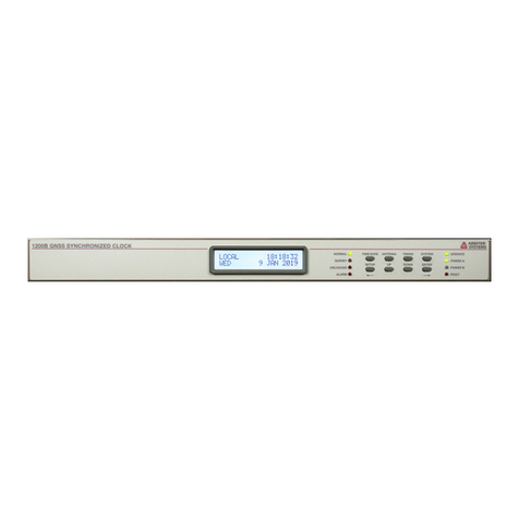
Figure 5-15 Standard Relay Configuration Menu ......................................................................................52
Figure 5-16 Network Status Page.............................................................................................................53
Figure 5-17 Ethernet Port Configuration Page ..........................................................................................54
Figure 5-18 Analog Input over IP Settings Page........................................................................................55
Figure 5-19 Serial Communications Port Settings Page............................................................................56
Figure 5-20 Programmable Pulse Settings Page.......................................................................................57
Figure 5-21 Open Drain Setup Menu........................................................................................................58
Figure 5-22 Modulated IRIG-B Setup Menu..............................................................................................59
Figure 5-23 Optional Programmable Pulse Output....................................................................................60
Figure 5-24 Auxiliary Programmable Pulse Select Menu...........................................................................60
Figure 5-25 Input Page Information ..........................................................................................................61
Figure 5-26 Viewing the Fault Status and Configuration............................................................................62
Figure 5-27 Configuring PTP Operation....................................................................................................63
Figure 5-28 PTP Status Page...................................................................................................................64
Figure 5-29 View and Configure NTP Operation.......................................................................................65
Figure 5-30 NTP/PTP Uncertainty Measurements ....................................................................................66
Figure 5-31 Contact Support Page ...........................................................................................................67
Figure 5-32 Version Support.....................................................................................................................67
Figure 5-33 Update Log Support ..............................................................................................................68
Figure 6-1 SSH Console Interface –Startup Screen.................................................................................69
Figure 6-2 Network Status Page Using SSH.............................................................................................70
Figure 6-3 Network Configure Page Using SSH........................................................................................71
Figure 6-4 Admin Configure Page Using SSH...........................................................................................71
Figure 6-5 Configure Password Using SSH..............................................................................................72
Figure 6-6 Update Firmware Using SSH...................................................................................................72

13
Figure 6-7 Reboot the System Using SSH................................................................................................ 73
Figure 6-8 Arbiter Contact Information Using SSH.................................................................................... 73
Figure 6-9 Firmware Update Log Page Using SSH................................................................................... 74
Figure 9-1 IRIG-B Waveforms.................................................................................................................. 82
Figure 9-2 DCF77 Timing Diagram –see Marker Details.......................................................................... 84
Figure 9-3 300-Volt FET with Pull-Down Resistor..................................................................................... 94
Figure 9-4 300-Volt FET with Voltage Source in Series............................................................................ 94
Figure 9-5 Main I/O Block Connector Diagram......................................................................................... 95
Figure 9-6 Main I/O Connector Function Label......................................................................................... 95
Figure 9-7 Main I/O Block Connect........................................................................................................... 95
Figure 10-1 Optional Mixed I/O Connectors............................................................................................ 100
Figure 11-1 Optional Mixed I/O Connectors (BNC & Fiber Optic, ST) ..................................................... 104
List of Tables
Table 2-1 Main Input/Output Functions and Connections.......................................................................... 22
Table 3-1 Antenna Mounting Kit Parts List................................................................................................ 26
Table 3-2 GNSS Cable Data and Accessory Information.......................................................................... 29
Table 4-1 List of Faults and Alarms.......................................................................................................... 32
Table 8-1 NTP/PTP Server LED Indications............................................................................................. 79
Table 9-1 IRIG-B Time Code Types Available.......................................................................................... 81
Table 9-2 Programmable Pulse Modes and Features............................................................................... 83
Table 9-3 DCF77 Marker Details.............................................................................................................. 84
Table 9-4 Vorne Out-of-Range Time Deviation Values............................................................................. 88
Table 9-5 Status Indications of Time Base Processor............................................................................... 88
Table 9-6 Fault Indications and Definitions............................................................................................... 89
Table 9-7 Holdover Oscillator and GNSS Fault/Status.............................................................................. 89
Table 9-8 Main I/O Block Functions and Connections............................................................................... 96

14
Chapter 1 Getting Started
1.1Overview
This manual describes the Model 1205B/C and Model 1206B/C, which are new GNSS
1
synchronized
clocks and use EPS
TM
technology. Consult this document for all necessary information for
configuring and operating these two models. The 1205B and 1206B do not have a large LED
time/date display, and the 1205C and 1206C have a second large LED time/date display.
1.2Security and Performance Advantages
Each Model 1205B/C and Model 1206B/C provides the utmost in timing stability, protection from
communication attacks and false GNSS signals. A new series of synchronized secure clocks by
Arbiter Systems, the Model 1205B/C offers two levels of ultra-stable, crystal holdover oscillator.
With either oscillator available to stabilize clock timing, the Model 1205B/C provides a high level of
timing stability in the presence of a false GNSS signal, or from losing the GNSS reception. Model
1206B/C with a rubidium oscillator provides the highest level of holdover stability.
Using “EPS” technology, for Enhanced Performance and Security, three components used provide
for secure clock operation include: (1) encryption protection for secure connections, (2) GNSS anti-
spoof shielding and (3) intelligent holdover capability. Additionally, clocks can synchronize to
multiple satellite receiver systems.
1.3Standard Features
With six standard outputs to provide unmodulated IRIG-B, 1 PPS and Programmable Pulse, each
clock has substantial drive capability to supply timing to multiple loads. Each clock can use two
current Global Network Satellite System (GNSS) receivers, which include US GPS, Russian
GLONASS, Chinese Beidou, and European Galileo.
Available options include redundant power supplies, optional outputs supporting several connector
types, several standard timing signals and a second, backup GNSS receiver.
Dedicated terminals on the rear-panel, main connector are configured for event capture. Event
timing has 100 nanosecond resolution, and the clock sequentially records up to fifty events
internally.
Each model includes exceptional accuracy and stability across the board, due to ultra-stable
holdover oscillator with guaranteed holdover capability of less than 1 ms/day. The Model 1206B/C
has a rubidium oscillator with the ultimate in holdover stability of less than 1 µs/day, but otherwise
has the same features as the Model 1205B/C.
1
GNSS stands for Global Navigation Satellite System, and includes the US GPS, Russian GLONASS, European
Galileo and Chinese Beidou systems.

15
1.4Standard Accessories
These are the included components and accessories shipped with the clock.
•
1205B/C or 1206B/C GNSS Synchronized Clock
•
Choice of internal power supply(s)
•
Antenna cable assembly: 50 feet of RG-6 cable with type F connectors
•
Universal GNSS antenna
•
Two rack-mount ears with hardware, mounted
•
Quick start guide
A full instrument manual is available for download from www.arbiter.com. A printed manual is
available to order.
1.4.1 Handling Precautions
Mechanical Shock:
Use care when handling the GNSSantenna asit may bedamaged if
dropped. Store the antenna in a safe place untilitsfinal installation.
Static Discharge:
These clocks use static-sensitive components and should be guarded against
static discharges. These components are protected. However, they are exposed when the cover is
removed.
CAUTION:
Connect only the antenna cable coming from the antenna into the rear-panel antenna
input connector. This connector leads to the GNSS receiver, which may be damaged by high
voltage or a static discharge. All Model 1200 series clocks have an internal surge arrestor to help
protect against nearby lightning strikes. However, the optional, external surge arrestor provides
additional protection. Formore surge arrestor information, see Section 3.3
1.4.2 Unpacking and Locating Accessories
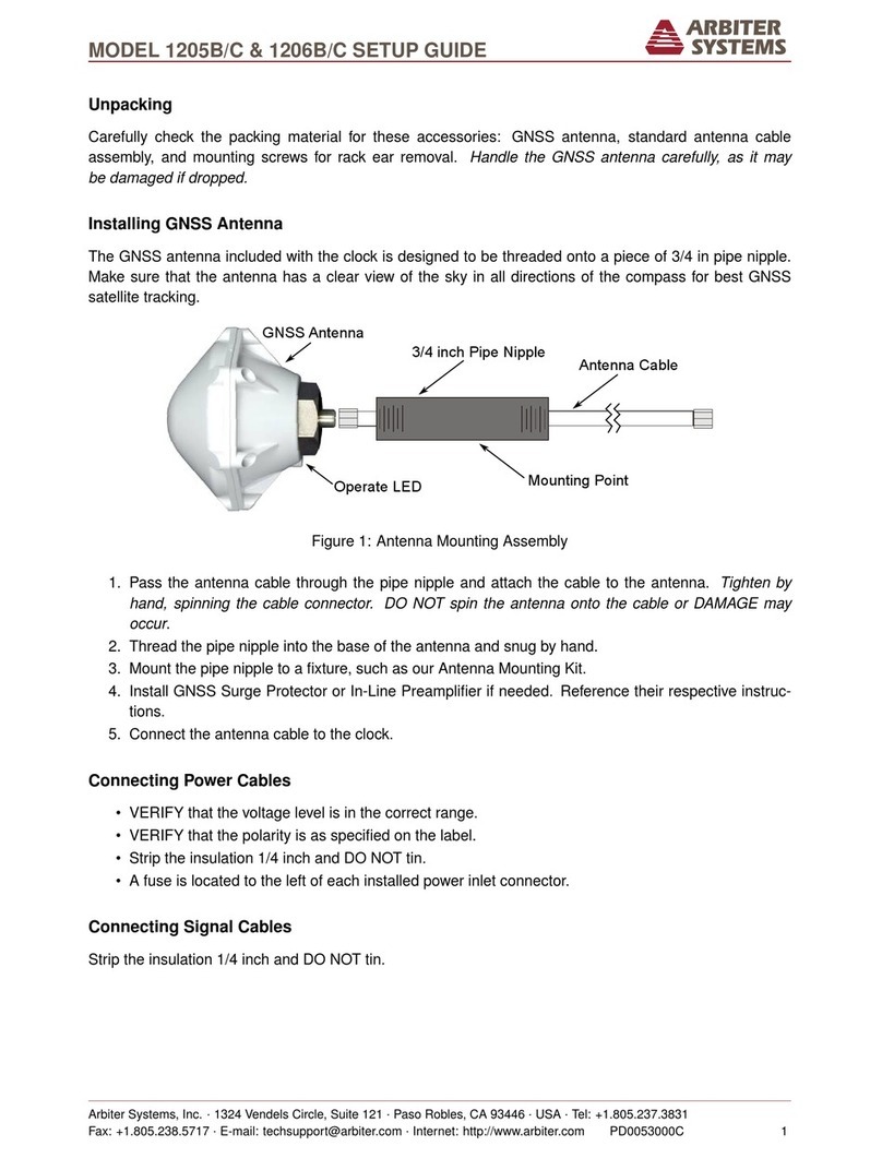
For shipping, the clock and included accessories are packaged in a carton with the clock held down
with a piece of plastic wrap with accessories stored below it. See Figure 1-1.
2.
Carefully grip points A and B and pull up. As the clock packaging expands outward, the
plastic wrap loosens so you can remove the clock.
3.
Some accessories (i.e., antenna, antenna cable and quick setup guide) are in
separate compartments. Two rack-mount ears are pre-installed.
4.
Handle the GNSS antenna carefully, as it may be damaged if dropped.
Figure 1-1 Packaging of Accessories

16
1.4.3 Removing Rackmount Ears
Each clock comes with pre-installed rack-mount ears suitable for mounting in a 19-inch rack. The
rack-mount ears may be removed if not needed.
Each rack-mount ear has two (2) M5x10mm flat head screws attaching it to the clock. The clock is
shipped with a bag labeled “AS0105000 Cover Screws” that contains four (4) M5x10mm pan-head
screws.
1.
Use a TorxT25 driver or large slot screwdriver to remove the two screws from each
rack-mount ear, freeing the rack-mount ear.
2.
Use a Torx T25 driver or slotted screwdriver to replace the removed screws with the
included M5x10 mm pan-head screws. NOTE: It is not recommended to reuse the
flat-head screws without the rack-mount ears.
Figure 1-2 Rack-Mount Ear Locations

17
Chapter 2 Front and Rear Panels
2.1Overview
This chapter identifies the connectors, controls, and displays found on the front and rear panels.
Figures 2.1 and 2.2 illustrate the front panels of the 1205B, 1205C, 1206B and 1206C clocks. “C”
clocks have a large LED display on the left side of the front panel. Models 1206B and 1206C have
air vents at the lower right of the front panel.
Figure 2-2 Model 1206B/C Front Panel View
Figure 2-1 Model 1205B/C Front Panel View

18
2.2Front Panel Controls and Indicators
All clocks have eight annunciator LED’s, a two-line by twenty-character LCD and eight-button
keypad; the Model 1205C and 1206C add a six-character, LED time/date display for greater
visibility. Most keys are informational only, except for the front-panel backlight control. The SETUP
key allows users to view the clock configuration if permitted under security settings.
Definitions for the annunciator LEDs and front panel keys are found below. Each of four upper keys
are defined to provide specific clock information, such as time and date, geographical position and
instrument status. The lower keys provide increased access within the individual menus.
2.2.1 Command Key Definitions
Figure 2.3 illustrates the keypad and annunciator LEDs, showing the placement and basic functions.
The details below provide additional description for each of these keys.
TIME/DATE: Press the TIME/DATE key to set the display(s) to the desired display mode. There
are four time/date display modes available, which are individually displayed by repeatedly
pressing the TIME/DATE key. Changing the front panel time display mode does not affect time
and date information broadcast from rear-panel timing outputs.
ANTENNA: Press the ANTENNA key to view the antenna status. Antenna status includes
antenna voltageandcurrent,GNSSsatellitetrackinginformation,signal-to-noiseratios,
longitude, latitude, and elevation of the antenna according to the most recent position fix.
TIMING: Press the TIMING key to view the clock status, time quality (time deviation and
sigma), holdover estimated uncertainty, and event/deviation values. Press the UP or DOWN
keys in the EVENT/DEVIATION menu to scroll through event records and display up to 50
recorded events. In the 1 PPS deviation mode, the display updates the 1 PPS deviation
data each second.
SYSTEM: Press the system key to view the clock serial number and firmware version, power
supply voltage(s), EEPROM status, faults, alarms, network status, NTP/PTP, analog input and
option board information.
SETUP: Press SETUP to view the clock configuration if security setting allows. Menus include:
COM1 settings, COM2 settings, local time offset, out of lock setting, relay configuration, back
light mode, (antenna) cable delay, I/O Block output configuration, event mode, option board
information.
UP: Used in conjunction with other menus for selection to scroll upward through the available
menu choices. Also assists in navigating through main menus in normal order.
DOWN: Used in conjunction with other menus for selection, or to scroll downward through
available menu choices.
DOWN
also assists in navigating through main menus in reverse order.
ENTER: Press
ENTER
to advance to a submenu of the current menu, if available. Forexample, in
the HD Output Current menu, press ENTER to open the submenu and press the UP/DOWN
keys to review the six high drive output current screens.
Figure 2-3 Keypad and Annunciator LEDs

19
2.2.2 LED Status Indicators
Figure 2.3 also illustrates the eight LED’s that provide information about the operational status of
the instrument. For normal operation, with the clock locked and accurate, the OPERATE LED and
POWER A and/or POWER B LED should be lit. While the clock is collecting position and timing
information the LEARN LED may be off and the NORMAL LED may be off. The following definitions
apply to these indicators:
LEARN: Illuminates orange when clock is finding its position and stabilizing: approximately 24 hrs.
GNSS anti-spoofing is not active.
NORMAL: Illuminates green when the clock has finished the learn mode. GNSS anti-spoofing is
active.
UNLOCKED: Illuminates red when the clock has never synchronized or has lost synchronization with
GNSS.
ALARM: Illuminates red when alarms are active.
OPERATE: Illuminates green when the clock is operating.
POWER A: Illuminates green when power supply A is providing power.
POWER B: Illuminates green when power supply B is providing power.
FAULT: Illuminates red when one or more fault conditions are active.
2.2.3 LCD Display
Each model has an LED backlit liquid crystal display (LCD), which provides a 20-characterby 2-line
readout. The readout displays instrument status, time and date, and instrument configuration.
2.2.4 Large LED Display: Model 1205C & Model 1206C
Models 1205C and 1206C add a six-character, 20-millimeter (0.8 inch) LED time and date display.
The LED display can indicate the time, in hours minutes and seconds, in local or UTC time zones.
Pressing the
TIME/DATE
key will also display the date format as MM/DD/YY or DD.MM.YY.
Configure date format from front panel or through the web interface.
2.2.5 USB
Each clock has a Micro-USB B male connector on the front panel. This port connects to a PC as a
serial port and allows for secure shell communication. The menu structure is the same as the
secure web interface connection. Defaults: 115200,8,N,1. See Chapter 6.
2.3Rear Panel Information
This section contains information to assist you in identifying where to connect inlet power, the
GNSS antenna cable, and all input and output connections on these clocks. Figure 2-4 and Figure
2-5 illustrate the rear panels of the Model 1205B/C and Model 1206B/C. Listed below are the
connectors grouped according to general clock functions, from left to right.
•
Three Ethernet ports –RJ45 connectors or Type LC Fiber Optic
•
32-pin multifunction I/O connector
•
Antenna input connector, antenna status LED, ground lug
•
Three optional I/O connector slots
•
Main power inlet –Power A; optional (redundant) power inlet –Power B

20
Figure 2-4
Model 1205B/C Rear Panel View
Figure 2-5 Model 1206B/C Rear Panel View
2.3.1 Power Inlet
Two different power supplies are available: Low voltage DC ONLY and Universal High Voltage
(AC/DC). Carefully examine the paperwork you received to make sure you have correctly identified
the inlet connections and voltages.
2.3.1.1 Universal Power Inlet
The universal power inlet allows high voltage ac and dc inputs. This includes a terminal power strip
with Surge Withstand Protect Circuitry (SWC), and inlet supply range of 85 Vacto 264 Vac, 47 Hz to
440 Hz for the Model 1205B/C and 47 Hz to 63 Hz for the Model 1206B/C. The dc range for both
products is 110 Vdc to 370 Vdc,
<
100 W typical.
2.3.1.2 Low DC Power Inlet
Terminal Power Strip with Surge Withstand Protect Circuitry (SWC), and inlet supply with a
range of 22 Vdc to 67 Vdc, DC ONLY.
Figure 2-6 Universal Power Supply Inlet Connector
Figure 2-7 Low DC Power Supply Inlet Connector
This manual suits for next models
3
Table of contents
Other Arbiter Systems Clock manuals

Arbiter Systems
Arbiter Systems 120A User manual

Arbiter Systems
Arbiter Systems 1095A User manual

Arbiter Systems
Arbiter Systems 1088A User manual

Arbiter Systems
Arbiter Systems 1205B User manual

Arbiter Systems
Arbiter Systems 1092A User manual

Arbiter Systems
Arbiter Systems 1205B User manual

Arbiter Systems
Arbiter Systems 1094B Installation manual

Arbiter Systems
Arbiter Systems 1200B User manual

Arbiter Systems
Arbiter Systems 1200B User manual

Arbiter Systems
Arbiter Systems 1095A User manual