Datcon DT13 Series User manual

DOC. N°:. DT1361-1393-62 Eng
Manufacturer: DATCON Ipari Elektronikai Kft.
H-1148 Budapest, Fogarasi út 5. 27. ép.
Phone:+36-1-460-1000, Fax.: 460-1001
DT13xx
Intrinsically Safe NAMUR / Contact
Isolators
User Manual
for the types
DT1361, DT1362, DT1363, DT1364, DT1371,
DT1372, DT1373, DT1381, DT1382, DT1384, DT1393
Revision 4
14.10.2021

2

3
Contents
1. Function and Scope of Application.....................................................................................................4
. ...........................................................................................................................................................4
2. Accessories of the device...................................................................................................................4
. ...........................................................................................................................................................4
3. Technical specifications .....................................................................................................................4
. ...........................................................................................................................................................4
4. Information for placing the order ........................................................................................................6
. ...........................................................................................................................................................6
4.1. Type selection range:................................................................................................................................6
4.2. Inputs with 0,5 mA current ........................................................................................................................7
. ...........................................................................................................................................................7
5. Operating principle .............................................................................................................................7
. ...........................................................................................................................................................7
6. Preliminary Instructions ......................................................................................................................8
. ...........................................................................................................................................................8
7. Putting the device into operation; Operating Instructions...................................................................8
. ...........................................................................................................................................................8
7.1. Safety measures .......................................................................................................................................8
7.2. Addition to the contacts installed in the explosive area ............................................................................9
7.3. Connecting the device...............................................................................................................................9
7.4. Putting the device into operation; Preliminary settings ...........................................................................12
. .........................................................................................................................................................13
8. Design ..............................................................................................................................................13
. .........................................................................................................................................................13
9. Maintenance, repair..........................................................................................................................13
. .........................................................................................................................................................13
10. Appendix ........................................................................................................................................14
. .........................................................................................................................................................14
10.1. ATEX Certification.................................................................................................................................14

4
1. Function and Scope of Application
.
The contact- and proximity-detector isolator family belongs to the group of associated apparatus in terms of
intrinsical safety. These devices are classified as II (1)G Ex ia GaIIC/IIB (-20 C ≤Ta ≤50 C) and
II (1)D Ex ia DaIIIC (-20 C ≤Ta ≤50 C) device.
The members of this device-family detect the logical status (near-remote, or open-closed) of the proximity
sensors („NAMUR”), or of the contacts working in explosive area, through a connection cable of practically any
length.
The devices are made in 1-, 2-, and 4-channel versions.
The output of the isolators is either a semi-conductor, or a relay of switching-contact or closing-contact type. In
the case of semi-conductor output the maximum signal transmission frequency is 5 kHz, which makes it suitable
for an application as a fast interface.
The high-capacity contact of the devices with relay output (loadability: 5 A and 250 Veff) is suitable for directly
controlling the parts of automatic systems.
With the DIL switches mounted inside the device it is possible to check if the detector cables are short or
broken. If such failure is found, the output is set automatically to open (broken) status. The logical status of the
output may be switched to Direct or to Reverse connection with the output.
The supply voltage range of the contact- and proximity-detector isolators is 19-29 V, allowing the usage of non-
stabilized power supply units too.
2. Accessories of the device
.
User Manual
CE Declaration of Conformity
Quality certificate
3. Technical specifications
.
Safety parameters:
Marking of intrinsical safety: II (1)G Ex ia GaIIC/IIB
II (1)D Ex ia DaIIIC
(-20 C ≤Ta ≤50 C)
Uo: 8.61V
Io: 11.6mA
Um: 250 VAC
Ci IIC / IIB: 2 F / 20 F
Li IIC / IIB: 100 mH / 200 mH
Input parameters:
Input signal: In accordance with the standard
MSZ EN 60947-5-6 (NAMUR), and
it can be operated also as a contact switch.
Idle voltage: 8.2 V 5%
Short-circuit current: 8.2 mA 6%
Input resistance: 1000
Levels defining the logical status of the input:
switch on > 2.1 mA
switch off < 1.2 mA
Detection of cable break: < 0.15 mA
Detection of cable short: > 6.0mA

5
Output parameters:
Devices with relay output
Loadability of relay contacts: 250 VAC, 5 A or 30 VDC, 5 A
Relay contact types: closing or switch-over (morse)
Maximum switching frequency: 12 Hz
Devices with electronic output .
Operating mode of the switched output: passive
(works with external supply voltage)
Max. voltage in OFF status: 30 VDC
Max. leakage current: 10 A
Max.current in ON status: 40 mA
Max. residual voltage (at 8 mA): < 1.8 V
(at 40 mA): < 2.5 V
Max. operating frequency: 5 kHz
General parameters:
Power supply: 19-29 VDC
Operating temperature range: -20 C - +50 C
Indicators (supply voltage) green LED
(output ON): yellow LED
(fault of the line to the detector):red LED
Shock protection: extra-low voltage (SELV)
Applied standards: MSZ EN IEC 60079-0:2018 (ATEX)
MSZ EN 60079-11:2012 (ATEX)
MSZ EN IEC 61326-1:2021 (EMC)
MSZ EN 55011:2016 (EMC)
MSZ EN 55011:2016/A1:2017 (EMC)
MSZ EN 55011:2016/A2:2021 (EMC)
MSZ EN IEC 63000:2019 (RoHS 2)
DIN19234 (NAMUR)
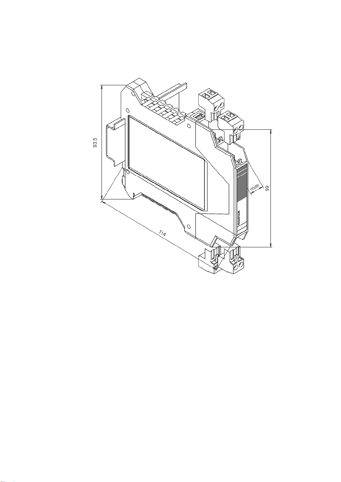
Box dimensions: 114 x 99 mm
(the width varies with the types)
(TS-35 is mountable on busbars)
Ambient conditions for storing:
Temperature: -40 C – +70 C
Relative air humidity: max. 80%, non-condensing

6
4. Information for placing the order
.
4.1. Type selection range:
Type
designation No. of
channels Output type Fault signal
output
Power
consumption
(W)
Box width
(mm)
DT1361 1 Relay switching contact - 0.6 17.5
DT1363 1 Relay closing contact 1 opening
contact 1.0 17.5
DT1371 1 Relay closing contact - 0.6 12.5
DT1381 1 Electronic passive - 0.6 12.5
DT1362 2 Relay switching contact - 1.0 22.5
DT1372 2 Relay closing contact - 1.0 17.5
DT1373 N 2 Relay closing contact * - 1.0 12.5
DT1373 P 2 Relay closing contact * - 1.0 12.5
DT1382 2 Electronic passive - 1.0 17.5
DT1393 N 2 Electronic passive * - 1.0 12.5
DT1393 P 2 Electronic passive * - 1.0 12.5
DT1364 4
Relay closing contact - 2.0 22.5
DT1384 N 4 Electronic passive - 1.6 22.5
DT1384 P 4 Electronic passive - 1.6 22.5
For each channel, one of the output pins with either 0 V or +24 V supply voltage
One of the output pins are commoned in each 2-2 channels
One of the output pins are commoned in each 2-2 channels or the negative or positive points
7
4.2. Inputs with 0,5 mA current
Inputs with 0.5 mA current are available optionally to satisfy specific customer needs.
Input parameters:
Short-circuit current: < 0.5 mA 6%
Input resistance: 18 k
.
5. Operating principle
.
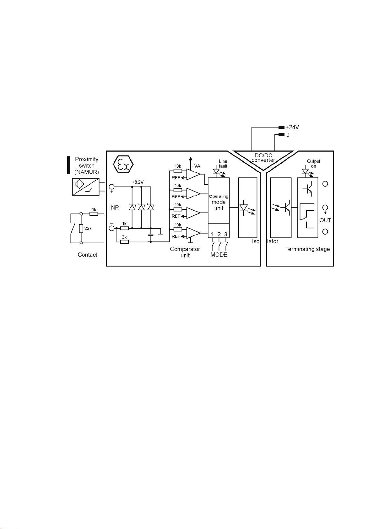
The operation of the device is shown in the block diagram of Figure 1.
Figure 1. The theoretical build-up of the device
The comparator unit detects the current flowing over the 1 kresistor connected serially with the +8.2 V voltage
generator. The threshold values in accordance with the NAMUR standard are as follows:
Direct switch position: > 2.1 mA
Reverse switch position: < 1.2 mA
Sensor line broken: < 0.15 mA
Sensor line short: > 6.0 mA
The following settings can be realized with the operating mode switch mounted inside the device (triple DIL-
switch):
S1, Direct – Reverse
S2, Detecting if the line is broken
S3, Detecting if the line is short
The function of detecting if the line is broken or short is applicable only when a NAMUR input detector is used!
In the case of operation with contact switch, the network in accordance with Figure 2 must be used for
establishing the connection to the contact switch ( S2 and S3 in ON position ).

8
Figure 2. Switch-positions of the device
The switching unit forwards the output signal of the comparators, depending on the setting of the operation
mode switch, to the isolator stage. In the case of relay-type output stage, it is the pulling coil of the relay, while
in the case of electronic output, it is the diode of an optical coupler.
The isolated output is either the contact of the relay or, in the case of electronic output stage, it is a PNP open
collector transistor, which gets its supply voltage from an external power supply unit.
A yellow LED indicates the ON status of the outputs. In the case of a line fault (broken or short) the red LED
gives light, and the output will be switched off.
The power supply for the two-stage (logical) intrinsically safe isolator is ensured by the DC/DC converter using
the 24 VDC, whose supply voltage may vary in a wide voltage range: 19-29 V. The supply voltage input is
protected against overvoltage.
6. Preliminary Instructions
.
The contact- and proximity-detector isolators and the User Manual are delivered in a packing that provide
appropriate protection. Special instructions for unpacking are not necessary.
Study the User Manual attentively before you put the device into operation, paying special attention to the
prescriptions ensuring an intrinsically safe operation, and to the safety measures.
7. Putting the device into operation; Operating Instructions.
.
7.1. Safety measures
In order to ensure the security of property and the safety of health and life of people, the following rules must be
met:
— Only properly qualified persons may put the device into operation.
— For making the connection of the screw-fixed type terminals, a cable with at least 0.5-2.5 mm2cross section
area must be used, whose insulation in radial direction is at least 0.2 mm
— The detector, or the contact, installed in the explosive area must be used concerning the cable that connects
the input of the isolators, it must be taken into consideration that intrinsical safety is ensured in that case only,
9
when the serial inductance and capacitance of the whole input circuit is not more than the values defined by the
Technical Specifications.
7.2. Addition to the contacts installed in the explosive area
If we want to apply a detection of the lines, the resistors necessary for the checking of the broken or short status
must be mounted to the switching contacts, and the DIL-switches mounted in the printed wiring within the device
must be set to the appropriate position.
7.3. Connecting the device
The various types should be connected in accordance with the following instructions:
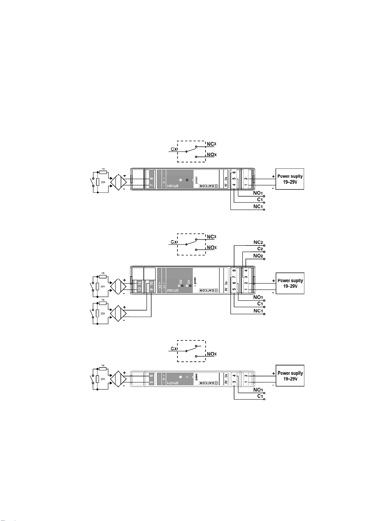
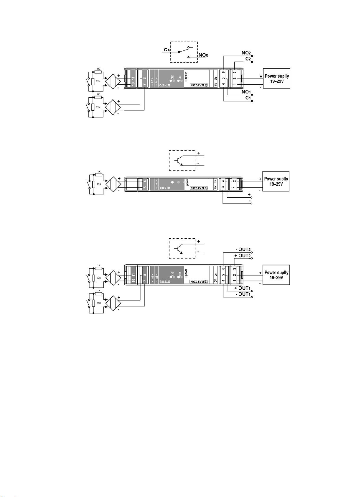
The types DT1361, DT1362, DT1371, DT1372, DT1381, and DT1382 have closing- and switching contacts, with
one or two channels. When these types are connected, the instructions under Clause 7.1 and Clause 7.2 must
be observed.
Connecting the output relay
Figure 3a. Connection of DT1361
Connecting the output relays
Figure 3b. Connection of DT1362
Connecting the output relays
Figure 3c. Connection of DT1371
10
Connecting the output relays
Figure 3d. Connection of DT1372
Connecting the output semi-conductor
Figure 3e. Connection of DT1381
Connecting the output semi-conductors
Figure 3f. Connection of DT1382
11
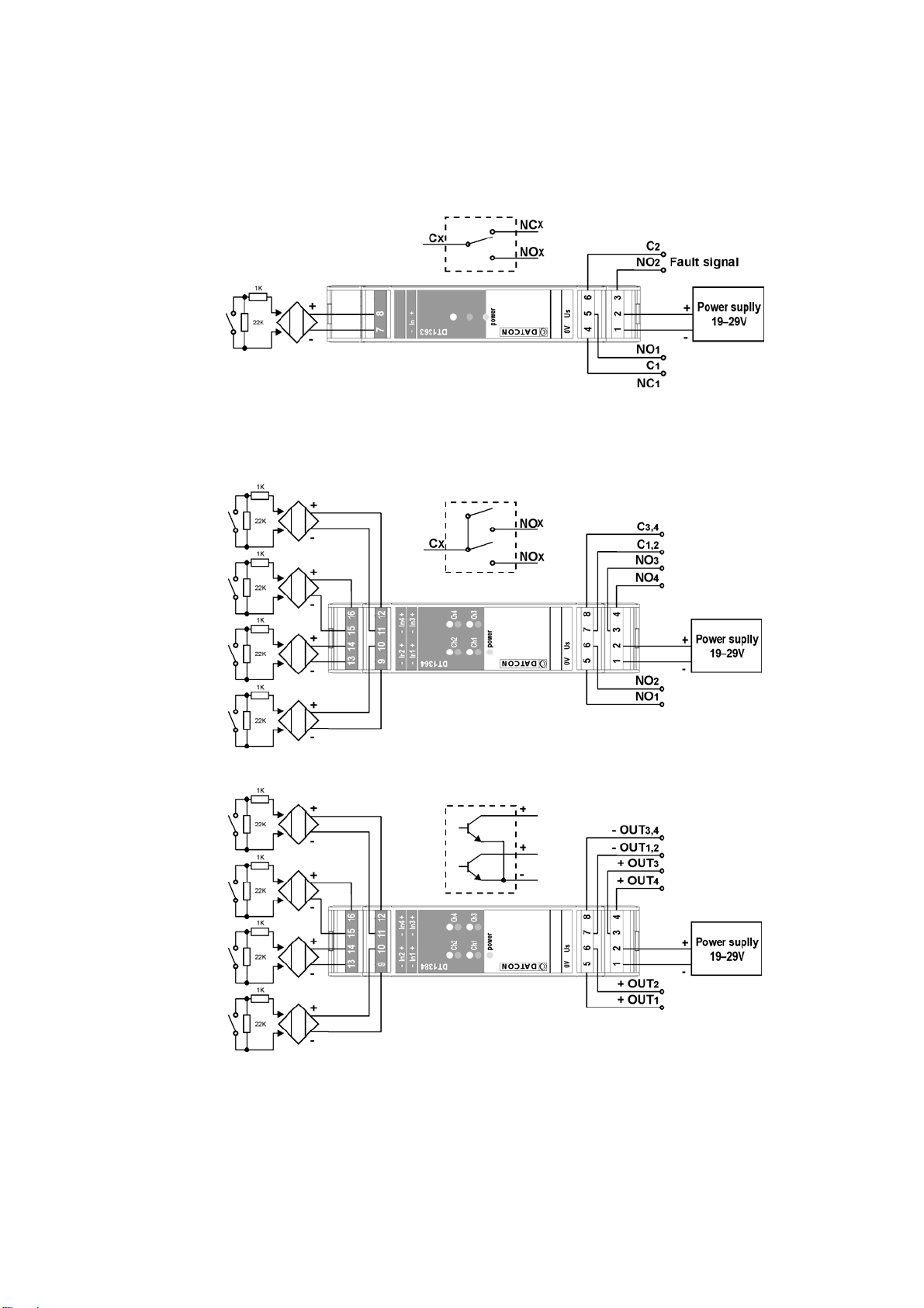
The type DT1363 is a single-channel device with closing contact, and with and additional fault-signal control
channel. At the output of the fault signal, a relay is found (whose type is identical with the one at the output of
the device). In the case of faultless operation its contact is in closed position. If some fault occurs (broken or
short line, no power supply), the fault signal relay will open the closing contact.
In order to ensure the proper operation of the fault signal relay, the fault signal detector switch, found inside the
device (S2 and S3) must be kept in ON status.
Connecting the output relays
Figure 3g. Connection of DT1363
The four-channel devices DT1364 and DT1384 include four independent channels. One of the terminations of
the outputs is commoned in each 2-2 channels.
Connecting the output relays
Figure 3h. Connection of DT1364
Connecting the output semi-conductors
Figure 3i. Connection of DT1384
12
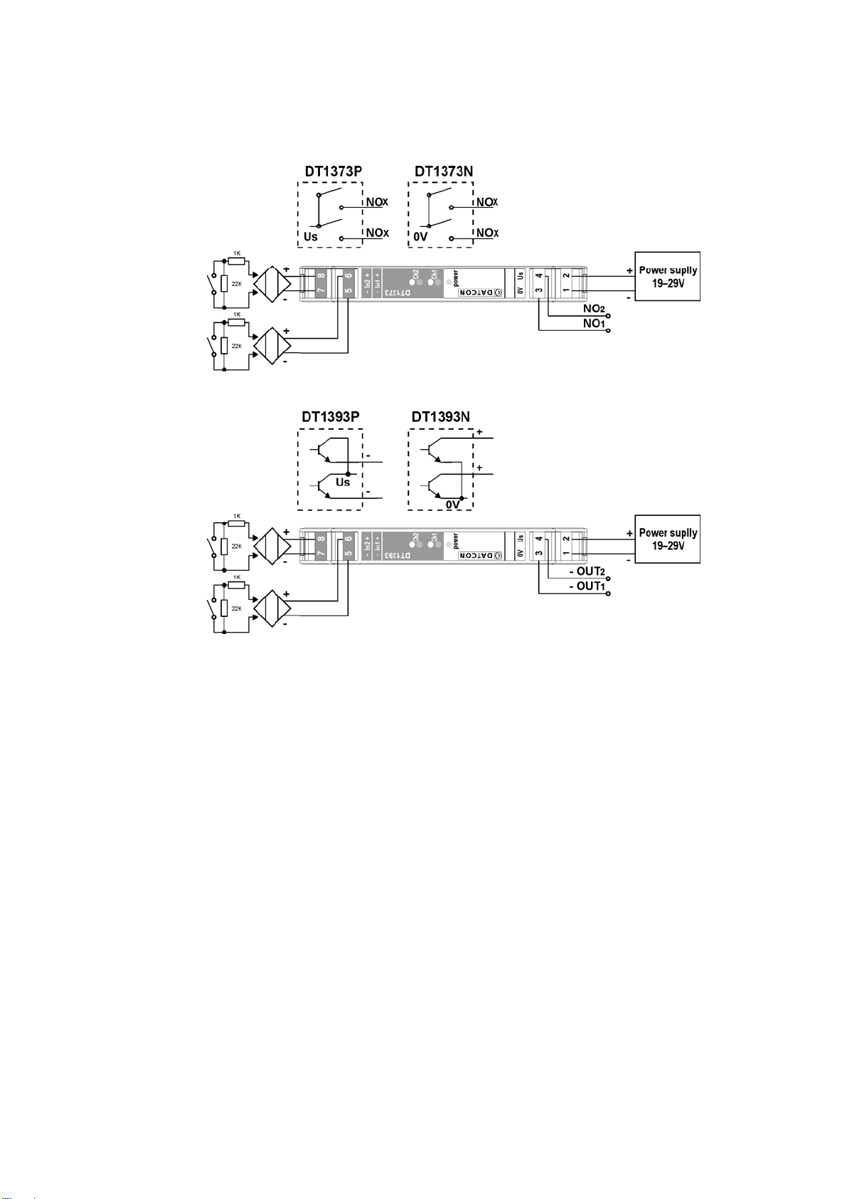
The types DT1373 and DT1393 are two-channel devices with relay closing contact or with semi-conductor
outputs. One of the terminals of the outputs are commoned with each-other and with one of the power supply
terminals (0 V or +24 V). In the lack of needs to the contrary, the devices as delivered by the Manufacturer are
commoned with the 0 V.
Connecting the output relays
Figure 3j. Connection of DT1373
Connecting the output semi-conductors
Figure 3k. Connection of DT1393
The types DT1381, DT1382, DT1384 and DT1393 have semi-conductor outputs, and passive operation (open-
collector output). By ensuring the right polarity, an external power supply unit should be connected to the output
through a resistor. The maximum voltage and current values of the external power supply unit are defined by
the Technical Specifications.
7.4. Putting the device into operation; Preliminary settings
After the MODE S1, S2, and S3 switches have been set previously (see Clause 5 and Figure 2), the
device should be put onto the busbar, and the connectors should be connected with the cables in
accordance with the above description.
13
.
8. Design
.
The isolators are built in a polyamide 6.6 box, that can be pushed on TS-35 type busbars, and ensure IP 20
protection. In terms of dimensions, only the width of the boxes vary, and it is shown under the point „Type
selection”. The drawing of the device’s housing (box) is presented by Figure 4.
Figure 4. Mounting of the device
9. Maintenance, repair
.
The isolators do not require maintenance.
Faulty units must be sent to the Manufacturer DATCON Kft for repair.

14
10. Appendix
.
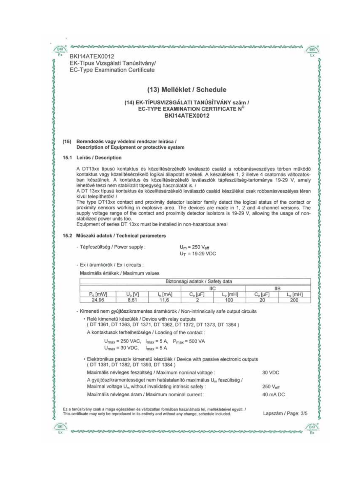
10.1. ATEX Certification

15
16

17
18

19

20
This manual suits for next models
11
Table of contents
Other Datcon Industrial Equipment manuals
 User manual")
 User manual")

Popular Industrial Equipment manuals by other brands


Habasit
Habasit Rossi IFIT Series operating instructions

MK
MK ZRF-P 2012 Technical documentation

Siemens
Siemens APACS+ Installation and service instruction

Energy Recovery
Energy Recovery PX G1300 Installation and operation manual

Saferoad
Saferoad MEGARAIL INSTRUCTION, INSTALLATION, MAINTENANCE AND REPAIR MANUAL

Spirax Sarco
Spirax Sarco CA44 Installation and maintenance instructions