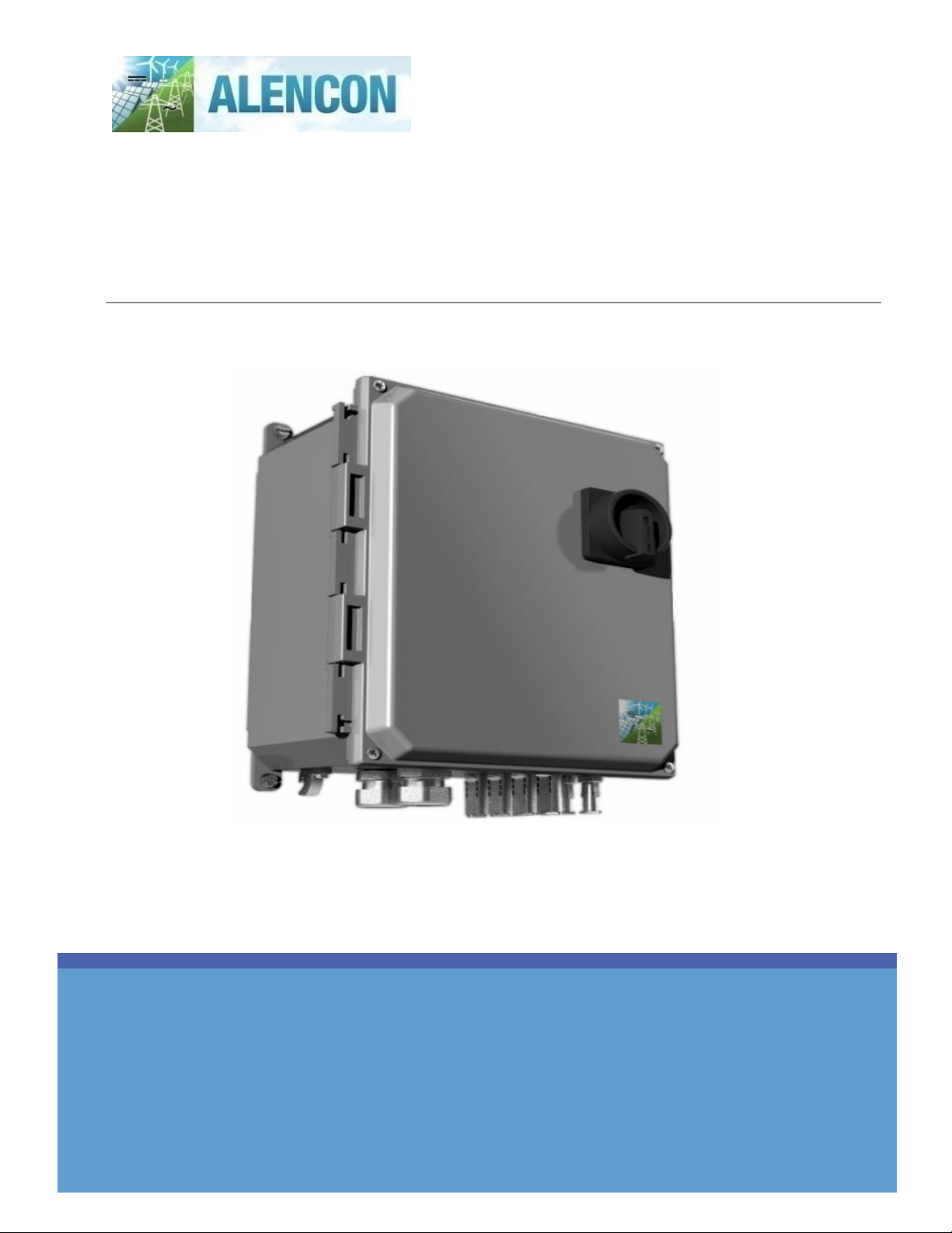
Alencon SPOT: Installation,
Operation, and Maintenance Manual
2 | P a g e
Contents
Disclaimer............................................................................................................................................ 1
1 Table of Figures................................................................................................................................. 3
2General Information..........................................................................................................................4
2.1 Purpose.......................................................................................................................................4
2.2 Product Warranty .......................................................................................................................4
2.3 Warnings, Cautions and Notes .................................................................................................... 5
2.4 Packing List.................................................................................................................................6
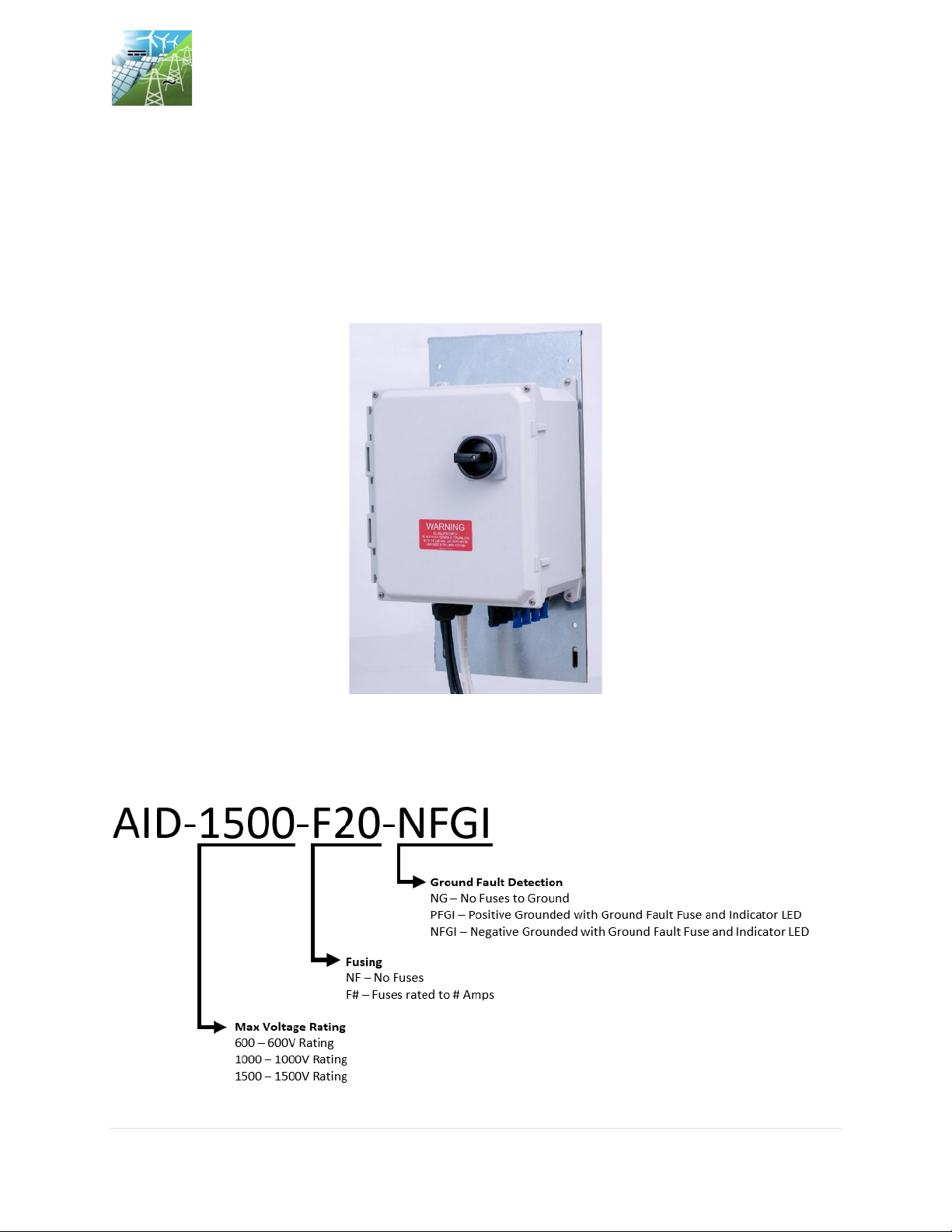
2.5 Ordering Information..................................................................................................................6
2.6 Technical Specifications.............................................................................................................. 7
3 Important Safety Instructions............................................................................................................8
4 Introduction ......................................................................................................................................9
4.1 Product Overview........................................................................................................................9
4.2 Disconnect Switch Operation......................................................................................................9
4.3 Fusing ....................................................................................................................................... 10
4.4 AID Enclosure ........................................................................................................................... 10
4.5 Grounding/Ground Fault Indication........................................................................................... 10
5 Installation ...................................................................................................................................... 11
5.1 Mounting Procedure –Separate Mounting Bracket................................................................... 11
5.2 Mounting Procedure –SPOT/BOSS Side Mounted ................................................................... 12
5.3 Connecting to Input and Output................................................................................................ 14
6 Servicing and Maintenance ............................................................................................................. 15
6.1 Opening and Closing AID for Service......................................................................................... 15
6.1.1 To Open the AID: ............................................................................................................... 15
6.1.2 To Close the AID: ............................................................................................................... 15
6.2 General Maintenance................................................................................................................ 16
6.2.1 Fuse Replacement: ............................................................................................................ 16
6.2.1 Additional Maintenance:.................................................................................................... 16
Appendix A - Safety Precautions.........................................................................................................17
A.1 Degree of Danger Symbols........................................................................................................17
A.2 Electrical hazards.......................................................................................................................17
A.2.1 Electric shock from live voltage..........................................................................................17
A.2.2 Electric shock caused by ground fault ............................................................................... 18
A.2.3 Electric shock due to damaged equipment........................................................................ 18