Datcon DT1102 (PS) User manual
DT1102 (PS)
Switch Configurable I/O Galvanic Isolator
Operating Instructions

DT1102 (PS)
220220202-V0
Contents
1. About this document..............................................................4
1.1. Function...............................................................................................4
1.2. Target group........................................................................................4
1.3. Symbolism used ..................................................................................4
2. For your safety........................................................................5
2.1. Authorized personnel...........................................................................5
2.2. Appropriate use ...................................................................................5
2.3. Warning about misuse.........................................................................5
2.4. General safety instructions ..................................................................5
2.5. CE conformity......................................................................................5
2.6. Environmental instructions...................................................................5
3. Product description................................................................6
3.1. Delivery configuration ..........................................................................6
3.2. Type designation .................................................................................6
3.3. Operating principle ..............................................................................7
3.4. Indicators, configuration switches ........................................................8
3.5. Input/output signal selection ................................................................9
3.6. Storage and transport........................................................................ 10
4. Mounting ...............................................................................11
4.1. General instructions........................................................................... 11
4.2. Main dimensions of the instrument .................................................... 11
4.3. Mounting procedure........................................................................... 12
5. Connecting............................................................................13
5.1. Preparing the connection................................................................... 13
5.2. Connecting active output current source to the input ......................... 14
5.3. Connecting 4-20 mA two wire (passive) transmitter to the input ........ 15
5.4. Connecting voltage source to the input.............................................. 16
5.5. Connecting current output to the signal processing unit .................... 17
5.6. Connecting voltage output to the signal processing unit .................... 18
5.7. Connecting instrument to the power supply ....................................... 19

DT1102 (PS)
20220202-V0 3
6. First „power on”, front panel indicators.............................20
6.1. First „power on” ................................................................................. 20
6.2. Front panel Indicators........................................................................ 20
7. Fault rectification..................................................................21
7.1. Fault finding....................................................................................... 21
7.2. Repearing.......................................................................................... 21
8. Dismounting..........................................................................22
8.1. Dismounting procedure...................................................................... 22
8.2. Disposal............................................................................................. 22
9. Appendix...............................................................................23
9.1. Technical specification ...................................................................... 23
9.2. Application example .......................................................................... 25
DT1102 (PS)
420220202-V0
start 1. About this document
1.1. Function
This operating instructions manual has all the information you need for
quick set-up and safe operation of DT1102 (PS)
Please read this manual before you start setup.
1.2. Target group
This operating instructions manual is directed to trained personnel.
The contents of this manual should be made available to these
personnel and put into practice by them.
1.3. Symbolism used
Information, tip, note
This symbol indicates helpful additional information.
Caution, warning, danger
This symbol informs you of a dangerous situation that could occur.
Ignoring this cautionary note can impair the person and/or the
instrument or it’s environ.
•List
The dot set in front indicates a list with no implied sequence.
→Action
This arrow indicates a single action.
1 Sequence
Numbers set in front indicate successive steps in a procedure.
DT1102 (PS)
20220202-V0 5
2. For your safety
2.1. Authorized personnel
All operations described in this operating instructions manual must be
carried out only by trained and authorized specialist personnel.
For safety and warranty reasons, any internal work on the instruments
must be carried out only by DATCON personnel.
2.2. Appropriate use
The DT1102 (PS) is an instrument for industrial use. Detailed
information on the application range is available in chapter 3. Product
description.
2.3. Warning about misuse
Inappropriate or incorrect use of the instrument can give rise to
application-specific hazards, or damage to system components
through incorrect installing or adjustment.
2.4. General safety instructions
Using the DT1102 (PS) requiring the strict observance of standards,
regulations and guidelines.
The user must take note of the safety instructions in this operating
instructions manual, the country-specific installation standards as well
as all prevailing safety regulations and accident prevention rules.
2.5. CE conformity
The DT1102 (PS) is in conformity with the provisions of the following
standards:
EN IEC 61326-1 (EMC)
EN 61010-1 (Safety)
EN 61558-1 (Safety)
2.6. Environmental instructions
Protection of the environment is one of our most important duties.
Please take note of the instructions written in the following chapters:
•Chapter 3.6. Storage and transport
•Chapter 8.2. Disposal

DT1102 (PS)
620220202-V0
3. Product description
3.1. Delivery configuration
Delivered items The scope of delivery encompasses:
•DT1102 (PS)
•tool for switch setting
(in case of shipping more instrument only one tool is enclosed)
•documentation:
this operating instructions manual
certification
warranty
3.2. Type designation
DT1102 24 VDC power supply
DT1102 PS 230 V AC/DC power supply

DT1102 (PS)
20220202-V0 7
3.3. Operating principle
Area of application The DT1102 (PS) Switch Configurable I/O Galvanic Isolator
provide signal transmission and conversion between transmitters and
signal processing units.
The instruments feature complete 3-way isolation: the input, the
output and the power supply are isolated from each other.
The instrument has two inputs:
1. 0(4)-20 mADC current or*
2. 0(2)-10 VDC voltage*
and two outputs:
1. 0(4)-20 mADC current or*
2. 0(2)-10 VDC voltage.
* only one input and one output are active together
The input/output ranges are switch selectable.
The DT1102 (PS) - providing a 20 VDC, 20 mA supply on the input –
for supplying 4-20 mA passive transmitters.
The front panel LED indicators provide information about the
operating status of the device. (power on state, error states)
Principle of operation
The input current flows through the measuring resistor or the input
voltage divides through the attenuator. This voltage drop is led to a
24 bit A/D converter. The digital output signal of the A/D converter is
processed by a microcontroller.
The microcontroller produces a pulse width modulated (PWM) output
signal. The pulse width is proportional to the processed, measuring
value. The output pulse is galvanic isolated by an optocoupler. After
filtering the pulse is converted into analogue current or voltage signal.
The input/output ranges are switch configurable.
The internal power supplies are generated by an isolated dual output
DC/DC converter, using planar transformer technology.
Power supply The instrument has two different power supply version:
DT1102:
Power supply: 24 VDC ±10%
DT1102 PS:
Power supply: 230 V AC/DC ±10%

DT1102 (PS)
820220202-V0
3.4. Indicators, configuration switches
The following figure shows the indicators and the configuration
switches on the DT1102 (PS) front panel.
(1) configuration switches for selection input/output ranges
(2) red „error” indicator shows the error states
(3) green „on” indicator shows the power on state
DT1102 (PS)
20220202-V0 9
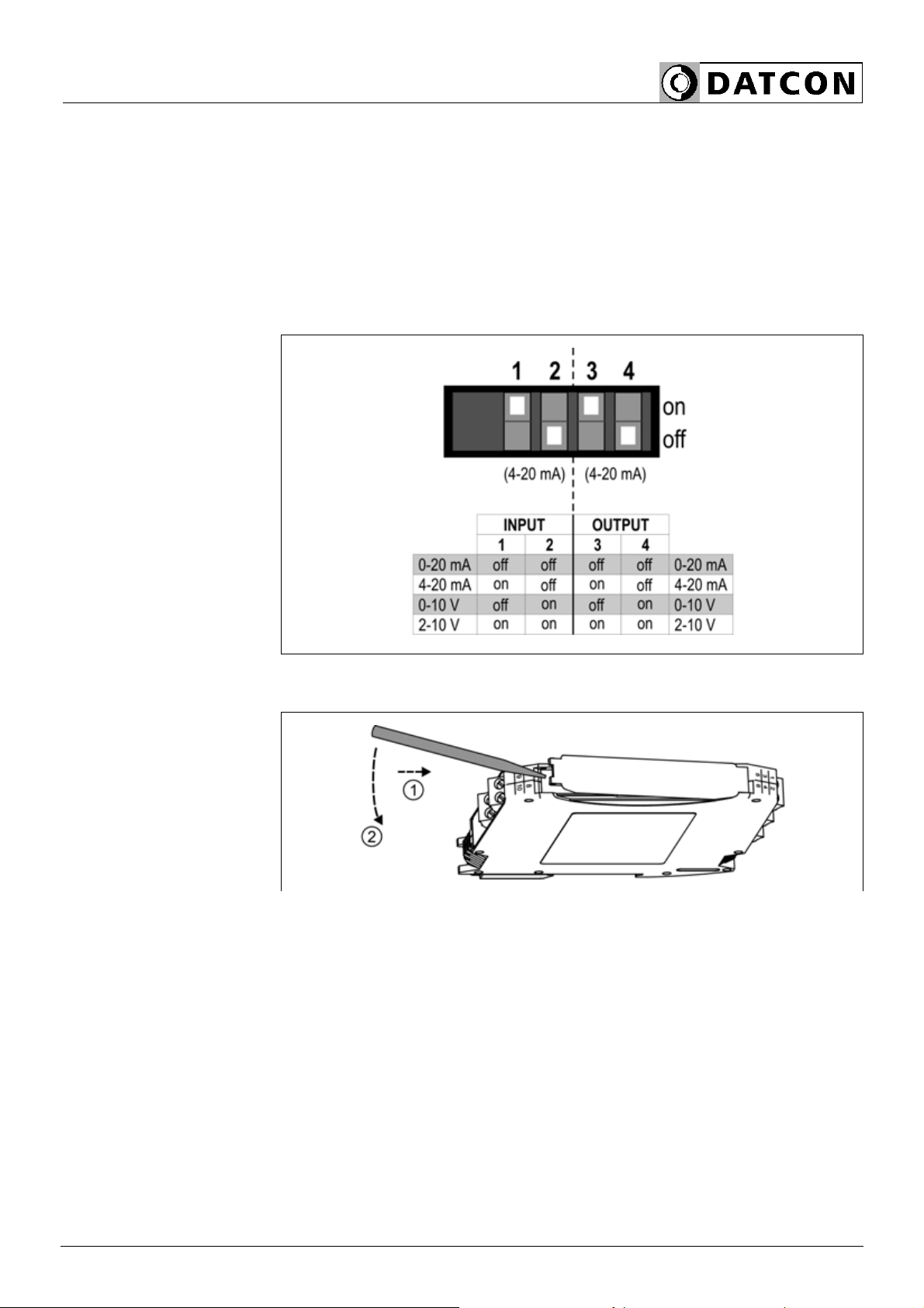
3.5. Input/output signal selection
Four different input/output signal range can be selected with the front
panel switches:
0-20 mA, 4-20 mA, 0-10 V, 2-10 V
Default setting: 0-20 mA input, 0-20 mA output
(all switches are in „off” state).
The following figure shows the input/output signal range selection
table:
The following figure shows steps of setting:
1. Take the instrument in hand according to the figure
2. Open the front panel cover with the enclosed tool according to the
figure
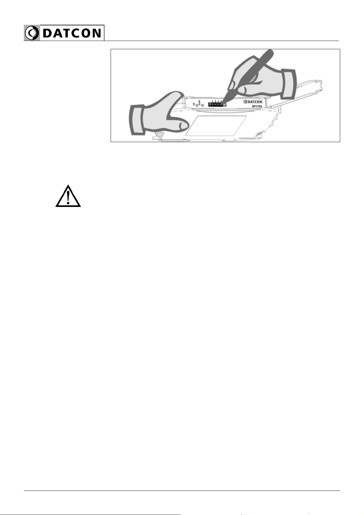
DT1102 (PS)
10 20220202-V0
3. Set the configuration switches according to the signal range
selection table
4. Close the front panel cover
Do not use other tool than the enclosed one because you may cause
injury either to switches or to front panel!
3.6. Storage and transport
This instrument should be stored and transport in places whose
climatic conditions are in accordance with chapter 9.1. Technical
specification, as described under the title: Environmental conditions.
The packaging of DT1102 (PS) consist of environment-friendly,
recyclable cardboard is used to protect the instrument against the
impacts of normal stresses occurring during transportation.
The corrugated cardboard box is made from environment-friendly,
recyclable paper. The inner protective material is nylon, which should
be disposed of via specialized recycling companies.
DT1102 (PS)
20220202-V0 11
4. Mounting
4.1. General instructions
The instrument should be installed in a cabinet with sufficient IP
protection, where the operating conditions are in accordance with
chapter 9.1. Technical specification, as described under the title:
Operating conditions.
Mounting position The DT1102 (PS) is built in a plastic housing, for mounting on TS-35
rail. Suggested mounting position: vertical (horizontal rail position).
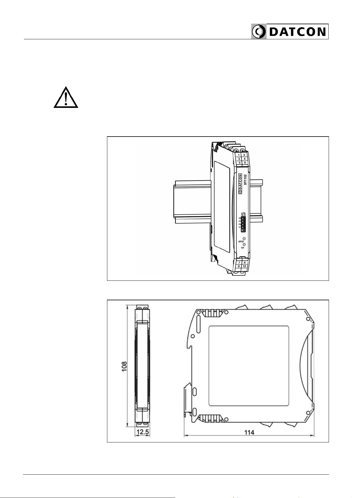
4.2. Main dimensions of the instrument
DT1102 (PS)
12 20220202-V0
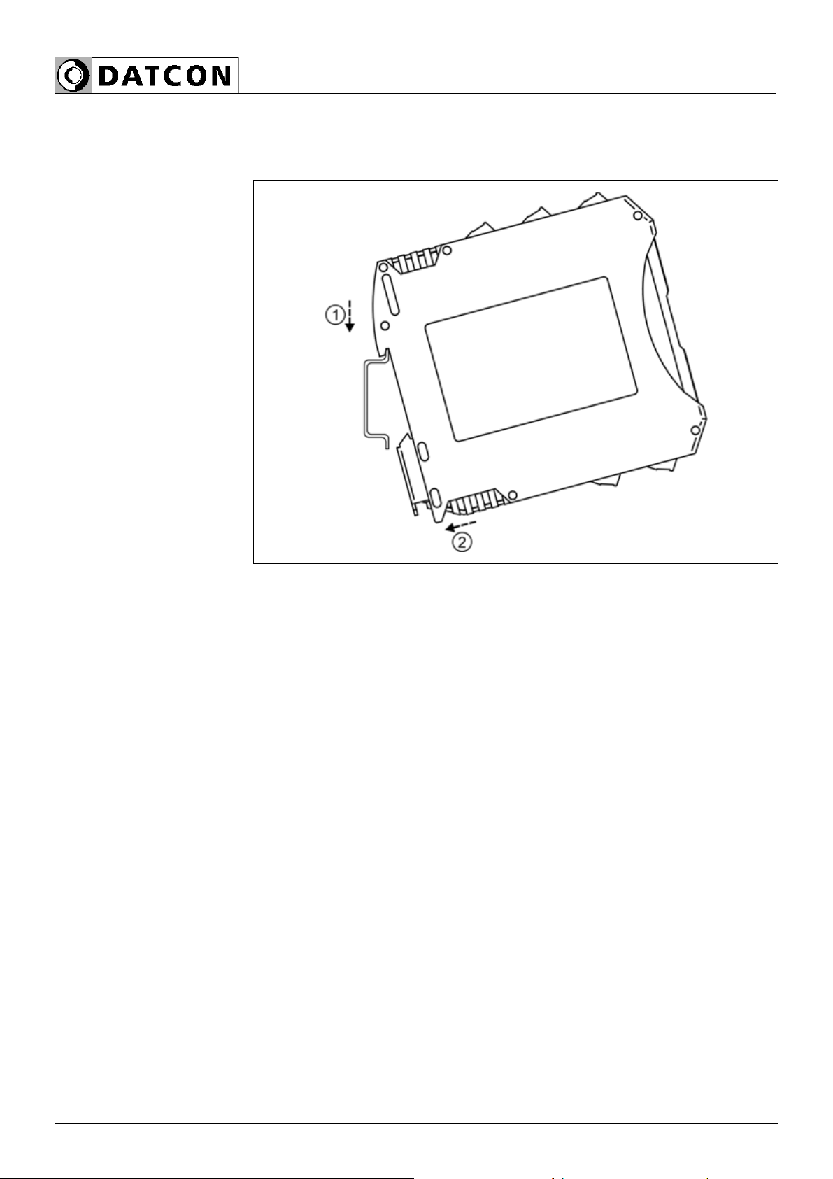
4.3. Mounting procedure
The following figure shows the mounting procedures (fixing on the
rail):
Mounting on the rail
The mounting doesn’t need any tool.
1. Tilt the instrument according to the figure; put the instrument’s
mounting hole onto the upper edge of the rail (figure step 1.).
2. Push the instrument’s bottom onto the bottom edge of the rail
(figure step 2.), you will hear the fixing assembly closing.
3. Check the hold of the fixing by moving the instrument firmly.

DT1102 (PS)
20220202-V0 13
5. Connecting
5.1. Preparing the connection
Select connection
cable
Preparing cables
Always observe the following safety instructions:
•The connection must be carried out by trained and authorized
personnel only!
•Connect or disconnect only in the complete absence of line voltage
•You should take note the data concerning on the overcurrent
protection in installation.
•Use only a screwdriver with appropriate head
Take note the suitability of the connecting cable
(wire cross-section, insulation, screening, etc.).
You may use either solid conductor or flexible conductor.
In case of using flexible conductor use crimped wire end.
The instrument can be connected with standard two-wire cable
without screen.
If electromagnetic interference is expected which is above the test
values of the correspondent standard for industrial areas (e.g. high
power frequency drives are working in the area) screened cable
should be used. Ground the cable shield on the cabinet side.
Always lead the signal cables on a separate path from the control and
power cables!
Prepare the cable for the connection. Strip approx. 8 mm insulation.
In case of using flexible conductor use crimped wire end.

DT1102 (PS)
14 20220202-V0
5.2. Connecting active output current source to the input
The following figure shows connecting active output current source to
the input:
Wiring plan, connecting
active output current
source
(see also “Application
example”)
Be careful the polarity of
the cables
1. Loosen terminal screws.
2. Insert the wire ends into the open terminals according to the wiring
plan.
3. Screw the terminal in.
4. Check the hold of the wires in terminals by pulling on
them firmly.
Terminal (8) and (10) are out of use!
Checking the
connections
Check if the cables are connected properly (have you connected all
the cables, have you connected to the right place, do not the cable-
ends touch each other).
DT1102 (PS)
20220202-V0 15
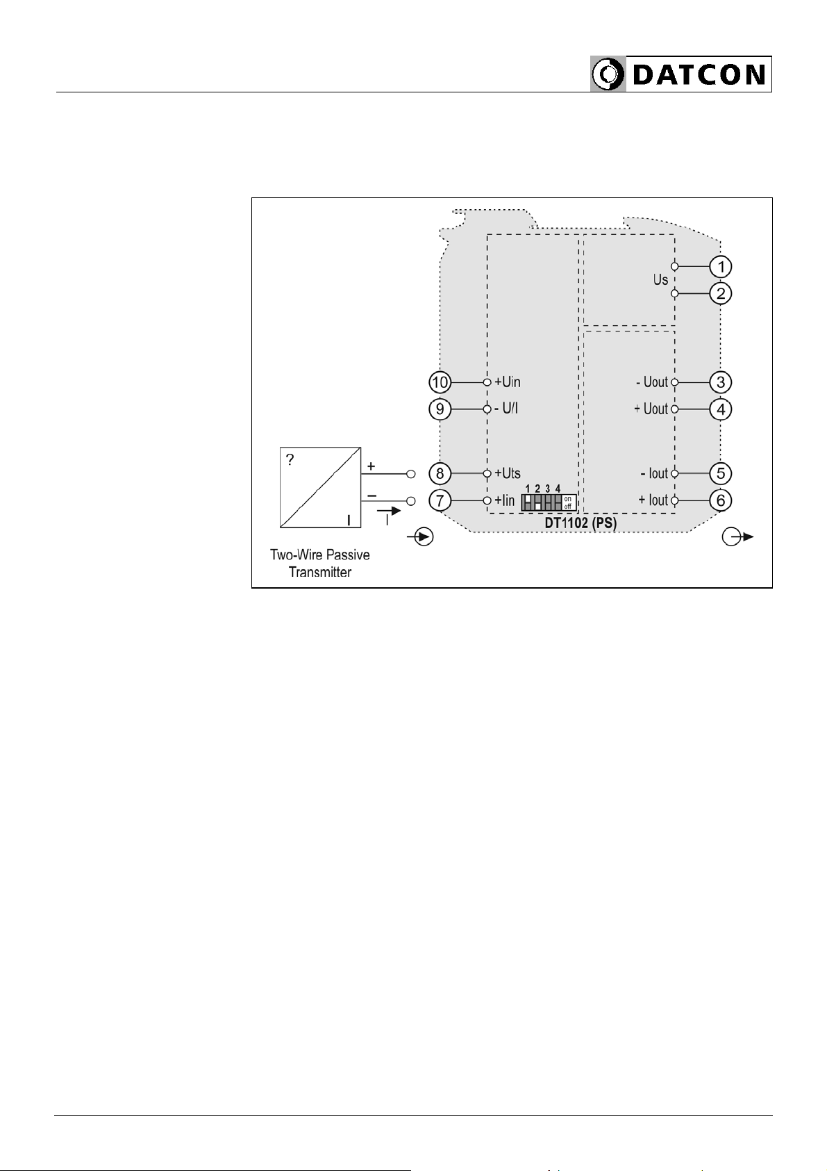
5.3. Connecting 4-20 mA two wire (passive) transmitter to the
input
The following figure shows connecting 4-20 mA two wire (passive)
transmitter to the input:
Wiring plan, connecting
4-20 mA two wire
transmitter (see also
“Application example”)
Be careful the polarity of
the cables
1. Loosen terminal screws.
2. Insert the wire ends into the open terminals according to the wiring
plan.
3. Screw the terminal in.
4. Check the hold of the wires in terminals by pulling on
them firmly.
Terminal (9) and (10) are out of use!
Checking the
connections
Check if the cables are connected properly (have you connected all
the cables, have you connected to the right place, do not the cable-
ends touch each other).
DT1102 (PS)
16 20220202-V0
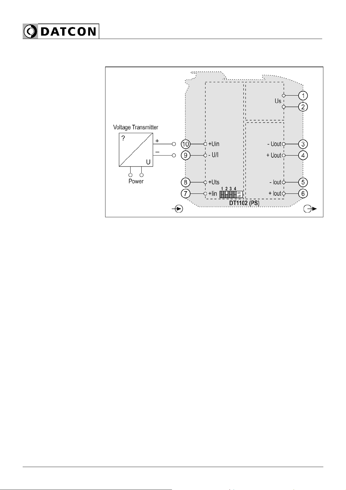
5.4. Connecting voltage source to the input
The following figure shows connecting voltage source to the input:
Wiring plan, connecting
voltage source
(see also “Application
example”)
Be careful the polarity of
the cables
1. Loosen terminal screws.
2. Insert the wire ends into the open terminals according to the wiring
plan.
3. Screw the terminal in.
4. Check the hold of the wires in terminals by pulling on
them firmly.
Terminal (8) and (7) are out of use!
Checking the
connections
Check if the cables are connected properly (have you connected all
the cables, have you connected to the right place, do not the cable-
ends touch each other).
DT1102 (PS)
20220202-V0 17
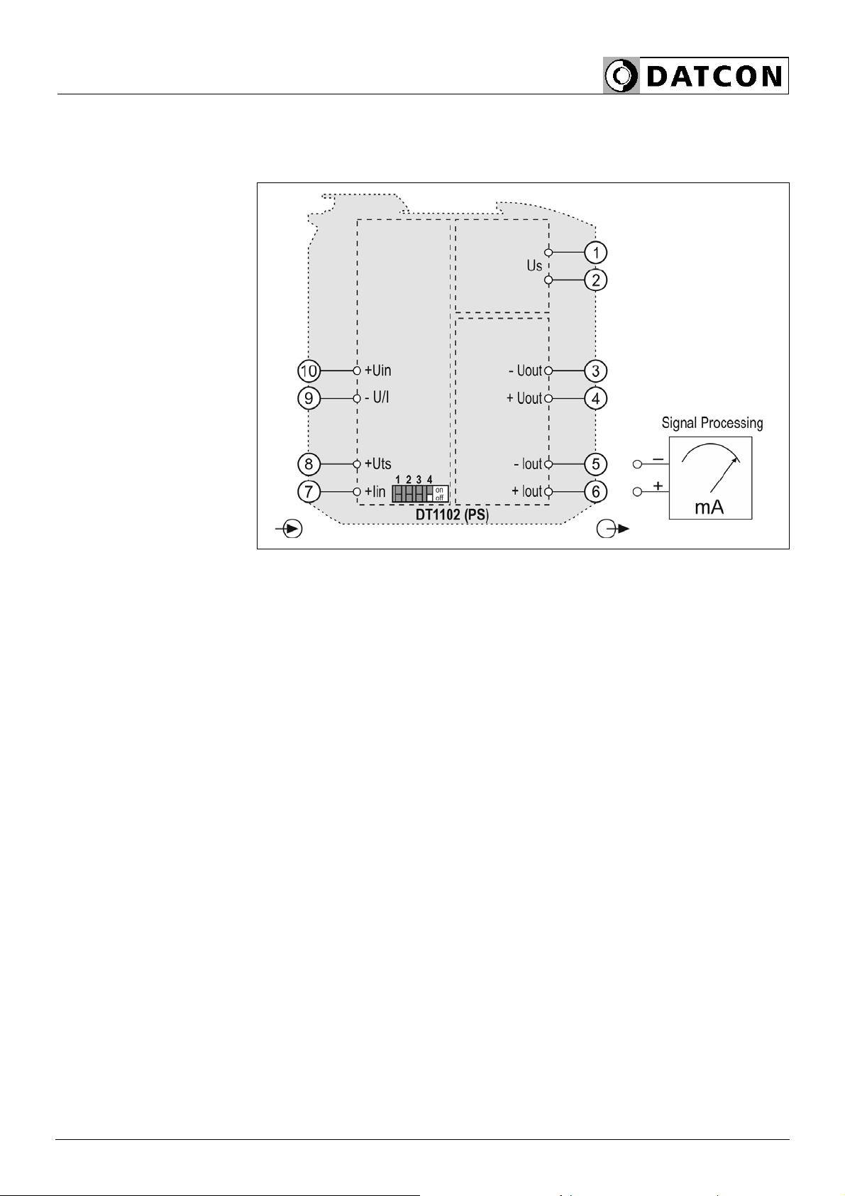
5.5. Connecting current output to the signal processing unit
The following figure shows connecting current output to the signal
processing unit:
Wiring plan, connecting
current output
(see also “Application
example”)
Be careful the polarity of
the cables
1. Loosen terminal screws.
2. Insert the wire ends into the open terminals according to the wiring
plan.
3. Screw the terminal in.
4. Check the hold of the wires in terminals by pulling on
them firmly.
Terminal (3) and (4) are out of use!
Checking the
connections
Check if the cables are connected properly (have you connected all
the cables, have you connected to the right place, do not the cable-
ends touch each other).
DT1102 (PS)
18 20220202-V0
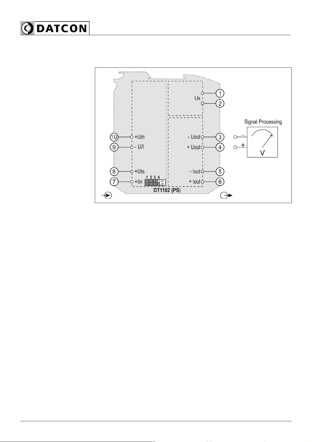
5.6. Connecting voltage output to the signal processing unit
The following figure shows connecting current output to the signal
processing unit:
Wiring plan, connecting
voltage output
(see also “Application
example”)
Be careful the polarity of
the cables
1. Loosen terminal screws.
2. Insert the wire ends into the open terminals according to the wiring
plan.
3. Screw the terminal in.
4. Check the hold of the wires in terminals by pulling on
them firmly.
Terminal (5) and (6) are out of use!
Checking the
connections
Check if the cables are connected properly (have you connected all
the cables, have you connected to the right place, do not the cable-
ends touch each other).
DT1102 (PS)
20220202-V0 19
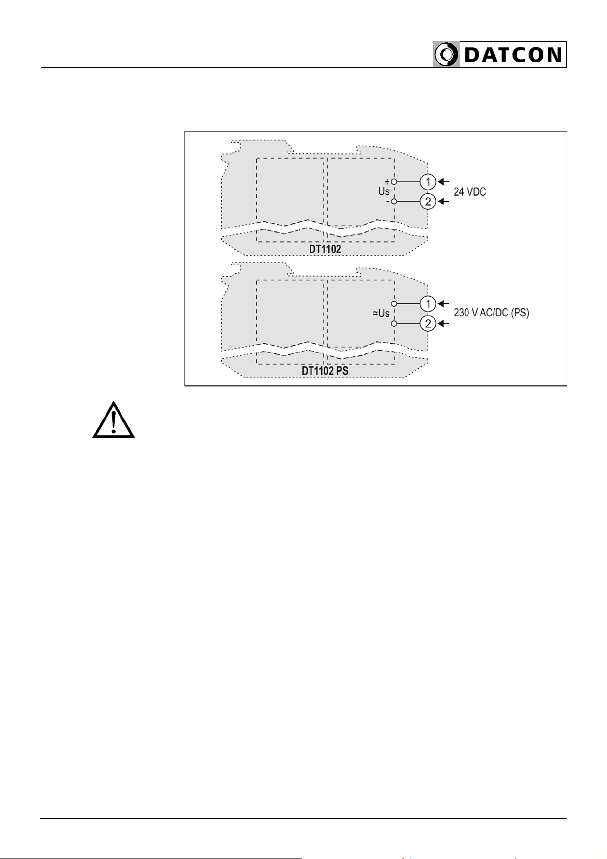
5.7. Connecting instrument to the power supply
The following figure shows connecting the instrument to the power
supply:
Wiring plan, connecting
the power supply
(see also “Application
example”)
The polarity of the cables
is indifferent
1. Before connecting check that the supply voltage correspond with
the supply voltage written on the data label. When the instrument type
designation ends with „PS” then the power supply terminal coloured
black.
2. Connect only in the complete absence of line voltage
3. Loosen terminal screws.
4. Insert the wire ends into the open terminals according to the wiring
plan.
5. Screw the terminal in.
6. Check the hold of the wires in terminals by pulling on
them firmly.
Checking the
connections
Check if the cables are connected properly (have you connected all
the cables, have you connected to the right place, do not the cable-
ends touch each other).

DT1102 (PS)
20 20220202-V0
6. First „power on”, front panel indicators
6.1. First „power on”
After you have completed the connections, put the instrument under
supply voltage. If the connection is correct green “on” indicator lights,
red “error” indicator dark and you can measure the expected current
or voltage on the output.
Warning! Insufficient setting or connection may cause improper
working of the instrument or in certain situation may cause impairment
of the instrument!
6.2. Front panel Indicators
•In normal (working) mode:
Green „on” indicator lights, red „error” indicator dark.
•Under configuration (switch setting):
Green „on” indicator goes out 1, 2, 3, 4 times according to the number
of the switch which state was changed.
•In error state:
Green „on” indicator lights, red „error” indicator flashes periodically
according to the error type:
1 flash/sec + break: the instrument is defective
4 flash/sec + break: input out of range
5 flash/sec + break: output out of range
Table of contents
Other Datcon Industrial Equipment manuals
 User manual")


Popular Industrial Equipment manuals by other brands


TLV
TLV PowerTrap GP5C instruction manual

Eaton
Eaton Cutler-Hammer ATC-300 Instruction booklet

Parker
Parker Gemini GV6K Series Hardware installation guide

M.J. MALLIS GROUP
M.J. MALLIS GROUP SIAT SM 11-SP Instruction manual and spare parts list

ABB
ABB HT562672 Operation manual

ABB
ABB HT569761 Operation manual


