Datcon DT1300 Series User manual

DT1300 xx xx xx
Intrinsically Safe Isolator / Power Supplies
Operating Instructions

DT1300 xx xx xx
2 20171220-V0
Contents
1. About this document .....................................................4
1.1. Function ................................................................................... 4
1.2. Target group............................................................................. 4
1.3. Symbolism used....................................................................... 4
2. For your safety ...............................................................5
2.1. Authorized personnel ............................................................... 5
2.2. Appropriate use........................................................................ 5
2.3. Warning about misuse ............................................................. 5
2.4. General safety instructions....................................................... 5
2.5. EU conformity........................................................................... 5
2.6. Safety information for Ex areas................................................ 6
2.7. Environmental instructions ....................................................... 6
3. Product description .......................................................7
3.1. Delivery configuration............................................................... 7
3.2. Type designation...................................................................... 7
3.3. Principle of operation ............................................................... 7
3.4. Adjustment ............................................................................... 8
3.5. Indicator ................................................................................... 8
3.6. Storage and transport .............................................................. 9
4. Mounting.......................................................................10
4.1. General instructions ............................................................... 10
4.2. Main dimensions of the instrument ........................................ 10
4.3. Mounting procedure ............................................................... 11
5. Connecting ...................................................................12
5.1. Preparing the connection ....................................................... 12
5.2. Connecting the transmitter ..................................................... 13
5.3. Connecting the signal processing unit and the power supply 14
6. Fault rectification .........................................................15
6.1. Fault finding............................................................................ 15
6.2. Repairing................................................................................ 15

DT1300 xx xx xx
20171220-V0 3
7. Dismounting .................................................................16
7.1. Dismounting procedure .......................................................... 16
7.2. Disposal ................................................................................. 17
8. Appendix.......................................................................18
8.1. Technical specification ........................................................... 18
8.2. Application example ............................................................... 20
8.3. ATEX Certification.................................................................. 21
DT1300 xx xx xx
4 20171220-V0
1. About this document
1.1. Function
This operating instructions manual has all the information
you need for quick set-up and safe operation of
DT1300 xx xx xx.
Please read this manual before you start setup.
1.2. Target group
This operating instructions manual is directed to trained
personnel. The contents of this manual should be made
available to these personnel and put into practice by them.
1.3. Symbolism used
Information, tip, note
This symbol indicates helpful additional information.
Caution, warning, danger
This symbol informs you of a dangerous situation that could
occur. Ignoring this cautionary note can impair the person
and/or the instrument.
Ex applications
This symbol indicates special instructions for Ex
applications.
•
List
The dot set in front indicates a list with no implied
sequence.
→
Action
This arrow indicates a single action.
1
Sequence
Numbers set in front indicate successive steps in a
procedure.

DT1300 xx xx xx
20171220-V0 5
2. For your safety
2.1. Authorized personnel
All operations described in this operating instructions
manual must be carried out only by trained and authorized
specialist personnel. For safety and warranty reasons, any
internal work on the instruments must be carried out only
by DATCON personnel.
2.2. Appropriate use
The DT1300 xx xx xx is an intrinsically safe isolator / power
supply product family. Detailed information on the
application range is available in chapter 3. Product
description.
2.3. Warning about misuse
Inappropriate or incorrect use of the instrument can give
rise to application-specific hazards, or damage to system
components through incorrect mounting or adjustment.
2.4. General safety instructions
The DT1300 xx xx xx is a high-tech instrument requiring
the strict observance of standard regulations and
guidelines.
The user must take note of the safety instructions in this
operating instructions manual, the country-specific
installation standards as well as all prevailing safety
regulations and accident prevention rules.
2.5. EU conformity
The DT1300 xx xx xx is in conformity with the provisions of
the following standards:
MSZ EN 60079-0:2013 (ATEX)
MSZ EN 60079-0:2013/A11:2014 (ATEX)
MSZ EN 60079-11:2012 (ATEX)
MSZ EN 61326-1:2013 (EMC)
MSZ EN 55011:2016 (EMC)
MSZ EN 55011:2016/A1:2017 (EMC)
MSZ EN 61010-1:2011 (LVD)
MSZ EN 50581:2011 (RoHS 2)

DT1300 xx xx xx
6 20171220-V0
2.6. Safety information for Ex areas
Please note the Ex-specific safety information for
installation and operation in Ex areas.
These safety instructions are part of Operating instructions,
and follows from regulations witch concerns the Ex
conformed devices.
2.7. Environmental instructions
Protection of the environment is one of our most important
duties.
Please take note of the instructions written in the following
chapters:
•Chapter 3.6. Storage and transport
•Chapter 7.2. Disposal
DT1300 xx xx xx
20171220-V0 7
3. Product description
3.1. Delivery configuration
Delivered items The scope of delivery encompasses:
•DT1300 xx xx xx
•documentation:
this operating instructions manual
certification
warranty
EU declaration of conformity
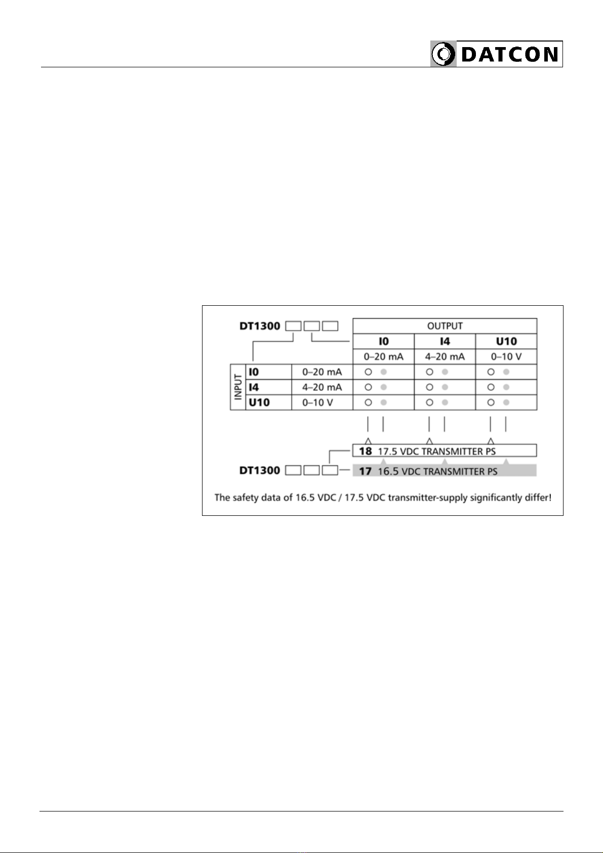
3.2. Type designation
3.3. Principle of operation
Area of application The DT1300 xx xx xx Intrinsically Safe Isolator / Power
Supplies provide signal transmission between transmitters
operate in zone 0, zone 1 potentially explosive area and
the signal processing unit operates in the safe area.
The instruments isolate the input, the output and the power
supply.
The intrinsically safe input signal may be:
0-20 mA, 4-20 mA, 0-10 V,
the output signal also may be:
0-20 mA, 4-20 mA, 0-10 V.
The isolators available with two different transmitter
supplies (17 VDC or 18 VDC nominally). The safety data
these two types differ considerably from each other, thus
they can be flexibly matched to the various transmitters.

DT1300 xx xx xx
8 20171220-V0
Operating principle
The instruments are powered from a 19-29 VDC supply
through a dual output high frequency DC-DC converter.
One output supplies power for the input (Ex) side and
supplies power for the transmitter connected to the input,
the other supplies power for the output (safe) side. The DC
isolation and intrinsically-safe segregation are provided by
high isolation optocoupler. The DC signal transmission
based on a high precision pulse modulation-demodulation
principle.
Power supply The instrument works from a 19-29 VDC supply voltage.
The power consumption is 2.2 W.
3.4. Adjustment
The DT1300 xx xx xx doesn’t need any adjustment.
After connected to the power supply it is ready to work.
3.5. Indicator
The following figure shows the indicator on the instruments
front:
1. “power” green indicator, indicates the power on state of
the instrument.

DT1300 xx xx xx
20171220-V0 9
3.6. Storage and transport
This instrument should be stored and transport in places
whose climatic conditions are in accordance with chapter
8.1. Technical specification, as described under the title:
Environmental conditions.
The packaging of DT1300 xx xx xx consist of environment-
friendly, recyclable cardboard is used to protect the
instrument against the impacts of normal stresses
occurring during transportation. The corragulated
cardboard box is made from environment-friendly,
recyclable paper. The inner protective material is polyfoam
and nylon, which should be disposed of via specialized
recycling companies.
DT1300 xx xx xx
10 20171220-V0
4. Mounting
4.1. General instructions
The instrument should be installing in the safe area in a
cabinet with sufficient IP protection, where the operating
conditions are in accordance with chapter 8.1. Technical
specification, as described under the title: Operating
conditions.
Mounting position
The instruments are designed in housing for mounting on
TS-35 rail.
The instruments should be mounted in vertical position
(horizontal rail position).
There are spacers both sides of the housing to keep 5 mm
distance between the instruments for the sufficient cooling.
Horizontal mounting may cause overheating and damage
of the instrument.
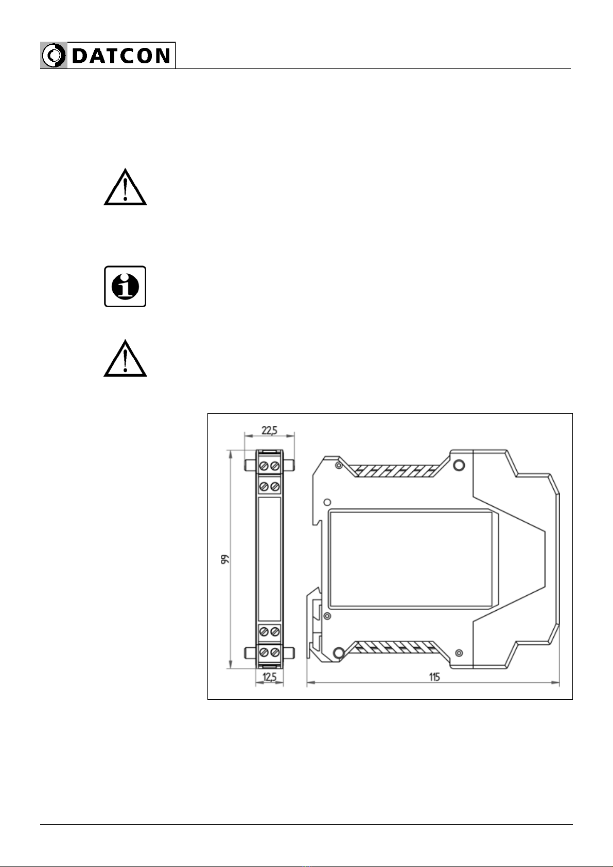
4.2. Main dimensions of the instrument

DT1300 xx xx xx
20171220-V0 11
4.3. Mounting procedure
The following figure shows the mounting procedures (fixing
on the rail):
Mounting on the rail
The mounting doesn’t need any tool.
1. Tilt the instrument according to the figure; put the
instrument’s mounting hole onto the upper edge of the rail
(figure step 1.).
2. Push the instrument’s bottom onto the bottom edge of
the rail (figure step 2.), you will hear the fixing assembly
closing.
3. Check the hold of the fixing by moving the instrument
firmly.
DT1300 xx xx xx
12 20171220-V0
5. Connecting
5.1. Preparing the connection
Select and prepare
connection cable
Always observe the following safety instructions:
• When you are going to install instruments in hazardous
area or install instruments which are connecting to
instruments are working in hazardous area you should take
note of the appropriate regulations, conformity and type
approval certificates of the DT1300 xx xx xx and other
instrument (e.g. transmitter). The connection must be
carried out by trained and authorized personnel only!
• Connect only in the complete absence of supply voltage
• Use only a screwdriver with appropriate head
Take note the suitability of the connecting cable
(wire cross-section, insulation, etc.).
The wire cross-section should be 0.25-1.5 mm2.
You may use either solid conductor or flexible conductor.
In case of using flexible conductor use crimped wire end.
Take note of the corresponding installation regulations for
Ex applications (MSZ EN 60079-25). In particular, make
sure that no potential equalization currents flow over the
cable screen. Ground only one side the cable screen (it’s
recommended the transmitter side). If necessary of
grounding on both sides (for suppress very high level, high
fequency interference signals) this can be achieved by use
separate potential equalization or by use of a blocking
capacitor (e.g. ceramic capacitor 1 nF, 1500 V) or. The low
frequency potential equalization currents are thus
suppressed, but the protective effect against high
frequency interference signals remains.

DT1300 xx xx xx
20171220-V0 13
5.2. Connecting the transmitter
The following figure shows the wiring plan, connecting the
transmitter:
Wiring plan, connecting
the transmitter
(see also “Application
example”)
Be careful the polarity of
the cables
1. Loosen terminal screws.
2. Insert the wire ends into the open terminals according to
the wiring plan.
3. Screw the terminal in.
4. Check the hold of the wires in terminals by pulling on
them firmly.
Checking the
connections
Check if the cables are connected properly (have you
connected all the cables, have you connected to the right
place, do not the cable-ends touch each other).

DT1300 xx xx xx
14 20171220-V0
5.3. Connecting the signal processing unit and the
power supply
The following figure shows the wiring plan, connecting the
signal processing unit and the power supply:
Wiring plan, connecting
the signal processing
unit and the power
supply
(see also “Application
example”)
Be careful the polarity of
the cables
1. Loosen terminal screws.
2. Insert the wire ends into the open terminals according to
the wiring plan.
3. Screw the terminal in.
4. Check the hold of the wires in terminals by pulling on
them firmly.
Checking the
connections
Check if the cables are connected properly (have you
connected all the cables, have you connected to the right
place, do not the cable-ends touch each other).
The connection is finished.
5.4. Put the instrument under supply voltage
Put the instrument
under supply voltage
After you have completed the connections, put the
instrument under supply voltage. If the connection is
correct the green indicator give light and you can measure
output current or voltage according to the measured value
of the transmitter.

DT1300 xx xx xx
20171220-V0 15
6. Fault rectification
6.1. Fault finding
The fault finding must be carried out by trained and
authorized personnel only!
Use only an Ex certificated measuring instrument when
measuring on the input (Ex) side.
•The green indicator is dark →check the power supply.
If the supply voltage is OK, the instrument is defective.
•There is no output signal →check the input signal.
If the input signal is OK, the instrument is defective.
•There is no input signal →check the transmitter supply.
If the transmitter supply is OK, the transmitter is defective.
When the result of fault finding is that the DT1300 xx xx xx
is defective call the manufacturer service department.
6.2. Repairing
There is no user repairable part inside the instrument.
In accordance with Chapter 2.1. Authorized personnel:
For safety and warranty reasons, any internal work on
the instrument must be carried out by DATCON
personnel.

DT1300 xx xx xx
16 20171220-V0
7. Dismounting
7.1. Dismounting procedure
The following figure shows the dismounting procedures:
Dismounting from the
rail
The dismounting procedure needs a screwdriver for slotted
screws.
Pull out all the terminals:
1. Put the screwdriver into the slot between the terminal
and the housing (figure step 1.).
2. Lift (lower terminals) or push down (upper terminal) the
screwdriver handle as far as the terminals will be free
(figure step 2.).
Dismount the instrument:
3. Put the screwdriver end into the fixing assembly’s hole
(figure step 3.).
4. Lift the screwdriver handle until it possible to open the
fixing assembly (figure step 4.).
5. Keeping the screwdriver in this position lift the
instrument bottom from the bottom edge of the rail (figure
step 5.).

DT1300 xx xx xx
20171220-V0 17
6.Lift the whole instrument (you may put out the
screwdriver) (figure step 6.), as far as the instrument will be
free.
(If necessary - after lose screws of terminals - pull the wire
out from connector block, then put in connector blocks
back to onto the instrument. There are coding pins on
connector blocks which prevent interchange of connector
blocks.)
7.2. Disposal
According with the concerning EU directive, the
manufacturer undertakes the disposal of the instrument
that are manufactured by it and intended to be destroyed.
Please deliver it in contamination-free condition to the site
of the Manufacturer or to a specialized recycling company.
DT1300 xx xx xx
18 20171220-V0
8. Appendix
8.1. Technical specification
Intrinsic safety data
Certification: BKI 14 ATEX 0013, BKI 14 ATEX 0013/1
Marking: II (1)G [Ex ia Ga] IIC / IIB (-20 °C ≤Ta ≤+50 °C
II (1)D [Ex ia Da] IIIC (-20 °C ≤Ta ≤+50 °C)
Safety data: DT1300 xx xx 17
IIC IIB
UoIoPoCo Lo Co Lo
Limit outputs safety data: 21 V 160 mA 850 mW 165 nF 1 mH 1 μF5 mH
Um: 250 Veff
Safety data: DT1300 xx xx 18
IIC IIB
UoIoPoCo Lo Co Lo
Limit outputs safety data: 26 V 95 mA 620 mW 88 nF 3 mH 680 nF 6 mH
Um: 250 Veff
Input parameters:
Input signal: DC current or DC voltage
Ranges: 0-20 mA (DT1300 I0 xx xx) or
4-20 mA (DT1300 I4 xx xx) or
0-10 V (DT1300 U10 xx xx)
Input resistance (current input): ~68 ohm
Input resistance (voltage input): ~1 Mohm
Overdriving ability: 5 %
Output parameters:
Output signal: DC current or DC voltage
Ranges: 0-20 mA (DT1300.xx I0 xx) or
4-20 mA (DT1300 xx I4 xx) or
0-10 V (DT1300 xx U10 xx)
Burden (current output): 800 ohm (max.) at 17.5 V transducer supply
600 ohm (max.) at 16.5 V transducer supply
Burden (voltage output): 500 ohm
Error of the output signal: 0.05% (max.) at Ta = 22 °C
Nonlinearity: 0.01% (max.)
Temperature-dependency: 50 ppm / °C (max.)
Supply-voltage dependency: practically zero
Response time: 10 ms (10-90%)

DT1300 xx xx xx
20171220-V0 19
Transmitter power supply:
Transmitter supply voltage, DT1300 xx xx 17: 16.5 VDC (at 20 mA load)
Transmitter supply voltage, DT1300 xx xx 18: 17.5 VDC (at 20 mA load)
Galvanic isolation:
Operating isolation voltage: 250 Veff (between the input, the output,
and the supply voltage terminals)
Test voltage: 2500 VDC (1 min.) (between the input and
the output terminals; between the input and
the power supply terminals)
Power supply:
Supply voltage: 19-29 VDC
Consumption: 2.2 W
Ambient conditions:
Operating temperature range: -20 °C ≤Ta ≤+50 °C
Relative air humidity: 90% (max., non-condensing)
Place of installation: safe area, cabinet
Installation: with 5 mm space, vertical position
Electromagnetic compatibility (EMC):
accordance with the standard MSZ EN 61326-1:2013
Immunity: Industrial area
Noise emission: Group 1, Class B
Data in general:
Housing: TS-35 rail mounting housing
material: polyamide PA6.6
Connection: plug-in screw terminal
Connecting cable: 1.5 mm2(max.)
Dimensions: 12.5 x 99 x 115 mm (width x height x depth)
Weigh: 0.15 kg
Protection: IP 20
The Manufacturer maintains the right to change technical data.

DT1300 xx xx xx
20 20171220-V0
8.2. Application example
Table of contents
Other Datcon Power Supply manuals


Popular Power Supply manuals by other brands

Lacme
Lacme UBI 10 000 / V100 user guide

MSI
MSI MPG A1000G PCIE5 user guide

Vimar
Vimar ELVOX 6941 Installer's guide

Simpex Electronic
Simpex Electronic MEAN WELL EDR Series installation manual

BEL
BEL LDC240 Seriesl LDC240-12 installation instructions

ITW
ITW Simco-Ion Chargemaster Pinner Superbar Installation and operating instructions


