Datcon DT1361 User manual
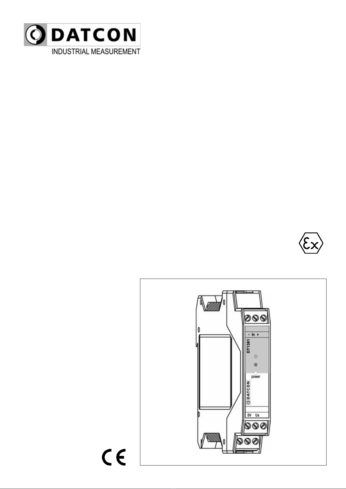
DT1361
Intrinsically Safe NAMUR / Contact Isolators
Operating Instructions

DT1361
2 20171206-V0
Contents
1. About this document.....................................................4
1.1. Function ................................................................................... 4
1.2. Target group............................................................................. 4
1.3. Symbolism used....................................................................... 4
2. For your safety...............................................................5
2.1. Authorized personnel ............................................................... 5
2.2. Appropriate use........................................................................ 5
2.3. Warning about misuse ............................................................. 5
2.4. General safety instructions....................................................... 5
2.5. EU conformity........................................................................... 5
2.6. Safety information for Ex areas................................................ 6
2.7. Environmental instructions....................................................... 6
3. Product description.......................................................7
3.1. Delivery configuration............................................................... 7
3.2. Principle of operation ............................................................... 7
3.3. Adjustment ............................................................................... 8
3.4. Indicators.................................................................................. 9
3.5. Storage and transport .............................................................. 9
4. Setting-up the operating modes.................................10
4.1. Open the instrument housing ................................................. 10
4.2. Setting up operating modes ................................................... 11
4.3. Close the instrument housing................................................. 12
5. Mounting.......................................................................13
5.1. General instructions ............................................................... 13
5.2. Main dimensions of the instrument ........................................ 13
5.3. Mounting procedure ............................................................... 14
6. Connecting ...................................................................15
6.1. Preparing the connection ....................................................... 15
6.2. Connecting the detector or the contact to the input. .............. 16
6.3. Connecting the relay contacts and the power supply............. 17
6.4. Put the instrument under supply voltage................................ 17

DT1361
20171206-V0 3
7. Fault rectification.........................................................18
7.1. Fault finding............................................................................ 18
7.2. Repairing................................................................................ 18
8. Dismounting.................................................................19
8.1. Dismounting procedure .......................................................... 19
8.2. Disposal ................................................................................. 20
9. Appendix.......................................................................21
9.1. Technical specification ........................................................... 21
9.2. Application example ............................................................... 23
9.3. ATEX Certification.................................................................. 24
DT1361
4 20171206-V0
1. About this document
1.1. Function
This operating instructions manual has all the information
you need for quick set-up and safe operation of DT1361.
Please read this manual before you start setup.
1.2. Target group
This operating instructions manual is directed to trained
personnel. The contents of this manual should be made
available to these personnel and put into practice by them.
1.3. Symbolism used
Information, tip, note
This symbol indicates helpful additional information.
Caution, warning, danger
This symbol informs you of a dangerous situation that could
occur. Ignoring this cautionary note can impair the person
and/or the instrument.
Ex applications
This symbol indicates special instructions for Ex
applications.
•List
The dot set in front indicates a list with no implied sequence.
→Action
This arrow indicates a single action.
1
Sequence
Numbers set in front indicate successive steps in a
procedure.

DT1361
20171206-V0 5
2. For your safety
2.1. Authorized personnel
All operations described in this operating instructions
manual must be carried out only by trained and authorized
specialist personnel. For safety and warranty reasons, any
internal work on the instruments must be carried out only by
DATCON personnel (except setting DIL switches).
2.2. Appropriate use
The DT1361 is a two channel intrinsically safe NAMUR /
contact isolator. Detailed information on the application
range is available in chapter 3. Product description.
2.3. Warning about misuse
Inappropriate or incorrect use of the instrument can give rise
to application-specific hazards, or damage to system
components through incorrect mounting or adjustment.
2.4. General safety instructions
The DT1361 is a high-tech instrument requiring the strict
observance of standard regulations and guidelines.
The user must take note of the safety instructions in this
operating instructions manual, the country-specific
installation standards as well as all prevailing safety
regulations and accident prevention rules.
2.5. EU conformity
The DT1361 is in conformity with the provisions of the
following standards:
MSZ EN 60079-0:2013 (ATEX)
MSZ EN 60079-0:2013/A11:2014 (ATEX)
MSZ EN 60079-11:2012 (ATEX)
MSZ EN 61326-1:2013 (EMC)
MSZ EN 55011:2016 (EMC)
MSZ EN 55011:2016/A1:2017 (EMC)
MSZ EN 61010-1:2011 (LVD)
MSZ EN 50581:2011 (RoHS 2)

DT1361
6 20171206-V0
2.6. Safety information for Ex areas
Please note the Ex-specific safety information for installation
and operation in Ex areas.
2.7. Environmental instructions
Protection of the environment is one of our most important
duties.
Please take note of the instructions written in the following
chapters:
•Chapter 3.5. Storage and transport
•Chapter 8.2. Disposal

DT1361
20171206-V0 7
3. Product description
3.1. Delivery configuration
Delivered items The scope of delivery encompasses:
•DT1361
•documentation:
this operating instructions manual
certification
warranty
3.2. Principle of operation
Area of application The DT1361 Intrinsically Safe NAMUR / Contact Isolator
is a single channel unit enable one safe area load to be
controlled by a proximity detector or a switch, located in a
potentially explosive area of zone 0 or zone 1.
The instrument galvanic isolates the input, the output and
the power supply. The safe output is a SPDT relay contact.
The DT1361 has a built-in mode-control switch for phase-
reverse control (allows an alarm condition to be signaled for
either state of the sensors), for on / off switch line
monitoring (wire short, wire open). The line fault detection
opens the output in the event of short or open-circuit lines:
intended for use primarily with proximity detectors. It can
also be used with switches made to resemble them
electrically by adding two resistors, or disabling by a switch
if not required.

DT1361
8 20171206-V0
Operating principle
The instrument is powered from a 19-29 VDC supply
through a DC-DC converter. The output supplies the input
circuit. The isolation and intrinsically-safe segregation are
provided by a high isolation relay. The input circuit provides
a 8.2 VDC supply voltage for the sensor through a 1 kohm
resistor. A multilevel comparator detects the current
consumption of the sensor (according with NAMUR
standard).
The levels are as follows:
> 2.1 mA ON (near) state
< 1.2 mA OFF (far) state
< 0.15 mA open circuit (wire broken) state
> 6 mA short circuit (wire short) state
The output relay is controlled by the comparator output in
conjunction of the states of mode switch.
Power supply The instrument works from a 19-29 VDC supply voltage.
The power consumption is 0.6 W.
3.3. Adjustment
The DT1361 operating modes can be set-up with the
internal three element DIL switch.

DT1361
20171206-V0 9
3.4. Indicators
The following figure shows the indicators on the instruments
front:
1. “power” green indicator, indicates the power-on state of
the instrument.
2. red indicator, indicates the line fault state
3. yellow indicator, indicates the output active state
3.5. Storage and transport
This instrument should be stored and transport in places
whose climatic conditions are in accordance with chapter
9.1 Technical specification, as described under the title:
Environmental conditions.
The packaging of DT1361 consist of environment-friendly,
recyclable cardboard is used to protect the instrument
against the impacts of normal stresses occurring during
transportation. The corrugated cardboard box is made from
environment-friendly, recyclable paper. The inner protective
material is polyfoam and nylon, which should be disposed of
via specialized recycling companies.

DT1361
10 20171206-V0
4. Setting-up the operating modes
The operating modes can be set-up with the internal DIL
switch (SW1). To reach the DIL switch the instrument
housing shall be open.
4.1. Open the instrument housing
The following figure shows how to open the instrument
housing:
Open the instrument
housing
Put the instrument on a clean surface prevent to get in any
alien material into the housing.
DT1361
20171206-V0 11
The opening procedure needs a screwdriver for slotted
screws
1. Push the upper opening lever of the housing with the
screwdriver end slightly (figure step 1.).
2. Draw back the upper part of the housing back cover, to
fix the opened position (figure step 2.)
3. Push the lower opening lever of the housing with the
screwdriver end slightly (figure step 3.).
4. Draw back the lower part of the back cover, to fix the
opened position (figure step 4.)
5. Draw back the cover as far as both of the DIL switches
can be seen (figure step 5.).
There is no need to use great force for pushing the opening
lever. Please do not exercise forces higher than necessary.
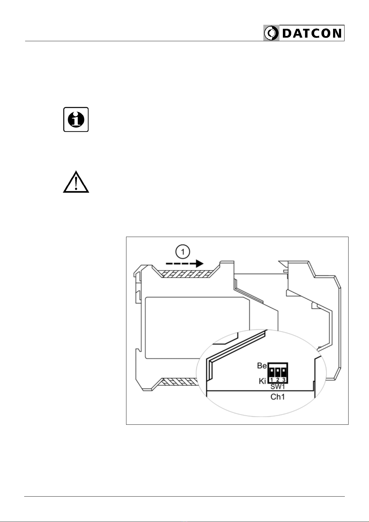
4.2. Setting up operating modes
The following figure shows the switch positions and the
operating modes:
Switch positions
Use a stylus or a pencil to change the switch positions.

DT1361
12 20171206-V0
SWx
123
input→output wire broken
detection
wire short
detection
On reverse yes yes
Operating modes
Factory default setting →Off normal no no
To use wire broken, wire short detection in a case of contact
input see 6.2. Connecting the detector or contact to the
inputs.
4.3. Close the instrument housing
Before pushing the cover back, check if any alien materials
left in the housing. If there are remove them.
The figure above shows how to close the instrument
housing.
1. Push back the cover (figure step 1.), you will hear
the fixing levers closing.
2. Check the hold of the levers by pulling away the two
sides of the housing firmly.
DT1361
20171206-V0 13
5. Mounting
5.1. General instructions
The instrument should be installed in the safe area in a
cabinet with sufficient IP protection, where the operating
conditions are in accordance with chapter 9.1 Technical
specification, as described under the title: “Operating
conditions”.
Mounting position
The instruments are designed in a housing for mounting on
TS-35 rail.
The instruments should be mounted in vertical position
(horizontal rail position).
Horizontal mounting may cause overheating and damage of
the instrument.
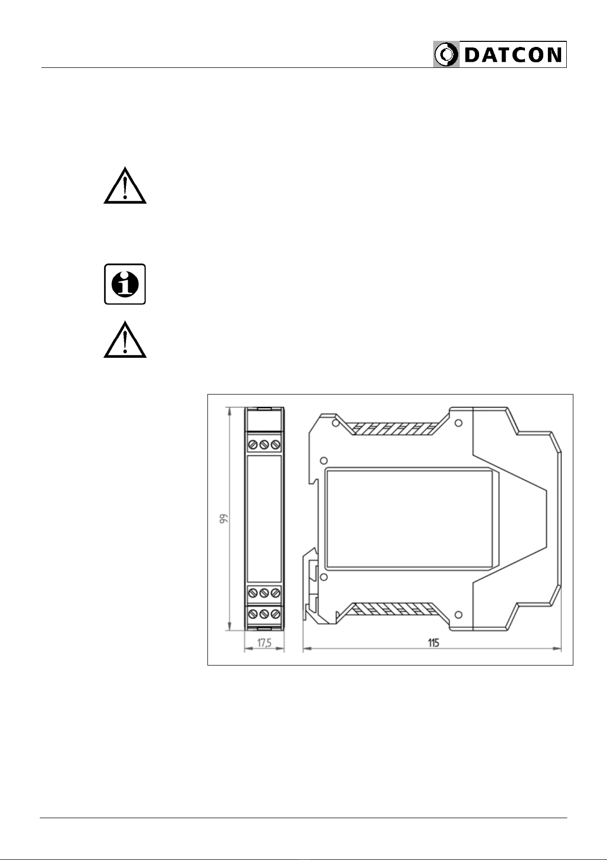
5.2. Main dimensions of the instrument

DT1361
14 20171206-V0
5.3. Mounting procedure
The following figure shows the mounting procedures (fixing
on the rail):
Mounting on the rail
The mounting doesn’t need any tools.
1. Tilt the instrument according to the figure; put the
instrument’s mounting hole onto the upper edge of the rail
(figure step 1.).
2. Push the instrument’s bottom onto the bottom edge of the
rail (figure step 2.), you will hear the fixing assembly
closing.
3. Check the hold of the fixing by moving the instrument
firmly.
DT1361
20171206-V0 15
6. Connecting
6.1. Preparing the connection
Select and prepare
connection cable
Always observe the following safety instructions:
• When you are going to install instruments in hazardous
area or install instruments which are connecting to
instruments working in hazardous area you should take
note of the appropriate regulations, conformity and type
approval certificates of the DT1361 and other connecting
instruments (e.g. detector). The connection must be carried
out by trained and authorized personnel only!
• Connect only in the complete absence of supply voltage
• Use only a screwdriver with appropriate head
Take note the suitability of the connecting cable
(wire cross-section, insulation, etc.).
The wire cross-section should be 0.25-1.5 mm2.
You may use either solid conductor or flexible conductor.
In case of using flexible conductor use crimped wire end.

DT1361
16 20171206-V0
6.2. Connecting the detector or the contact to the input.
The following figure shows the wiring plan, connecting the
detector or the contact to the input:
Wiring plan, connecting
the detectors or the
contacts to the inputs
(see also “Application
example”)
Be careful the polarity of
the cables
Checking the
connections
1. Loosen terminal screws.
2. Insert the wire ends into the open terminals according to
the wiring plan.
3. Screw the terminal in.
4. Check the hold of the wires in terminals by pulling on
them firmly.
Check if the cables are connected properly (have you
connected all the cables, have you connected to the right
place, do not the cable-ends touch each other).
DT1361
20171206-V0 17
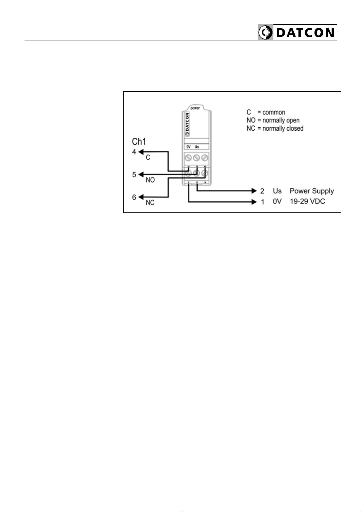
6.3. Connecting the relay contacts and the power
supply
The following figure shows the wiring plan, connecting the
relay contacts and the power supply:
Wiring plan, connecting
the relay contacts and
the power supply
(see also “Application
example”)
Checking the
connections
1. Loosen terminal screws.
2. Insert the wire ends into the open terminals according to,
the wiring plan.
3. Screw the terminal in.
4. Check the hold of the wires in terminals by pulling on
them firmly.
Check if the cables are connected properly (have you
connected all the cables, have you connected to the right
place, do not the cable-ends touch each other).
The connection is finished.
6.4. Put the instrument under supply voltage
Put the instrument
under supply voltage
After you have completed the connections, put the
instrument under supply voltage. If the connection is correct
the green indicator gives light and you can detect output
state according to the detector state.

DT1361
18 20171206-V0
7. Fault rectification
7.1. Fault finding
The fault finding must be carried out by trained and
authorized personnel only!
Use only an Ex proofed meter when measuring on the input
(EX) side.
•The green indicator is dark →check the power supply.
If the supply voltage is OK: the instrument is defective.
•The output state doesn’t change according the input state
→exchange the detector. If instrument works properly: the
detector is defective. If not: the instrument is defective.
When the result of fault finding is that the DT1361 is
defective call the manufacturer service department.
7.2. Repairing
There is no user repairable part inside the instrument.
In accordance with Point 2.1.: For safety and warranty
reasons, any internal work on the instrument must be
carried out by DATCON personnel (except setting DIL
switches).

DT1361
20171206-V0 19
8. Dismounting
8.1. Dismounting procedure
The following figure shows the dismounting procedures:
Dismounting from the
rail
The dismounting procedure needs a screwdriver for slotted
screws.
Pull out all the terminals:
1. Put the screwdriver into the slot between the terminal
and the housing (figure step 1.).
2. Lift (lower terminals) or push down (upper terminals) the
screwdriver handle as far as the terminals will be free
(figure step 2.).
Dismount the instrument:
3. Put the screwdriver end into the fixing assembly’s hole
(figure step 3.).
4. Lift the screwdriver handle until it possible to open the
fixing assembly (figure step 4.).
5. Keeping the screwdriver in this position lift the instrument
bottom from the bottom edge of the rail (figure step 5.).
6. Lift the whole instrument (you may put out the
screwdriver) (figure step 6), the instrument will be free.

DT1361
20 20171206-V0
8.2. Disposal
According with the concerning EU directive, the
manufacturer undertakes the disposal of the instrument that
are manufactured by it and intended to be destroyed.
Please deliver it in contamination-free condition to the site
of the Manufacturer or to a specialized recycling company.
Table of contents
Other Datcon Power Supply manuals


