ITW Simco-Ion Chargemaster Pinner Superbar User manual

Chargemaster Pinner Superbar 5101167 Rev. F
Chargemaster Pinner
Superbar
Arc Resistant Charging Applicator
INSTALLATION AND OPERATING INSTRUCTIONS

Chargemaster Pinner Superbar 5101167 Rev. F
TABLE OF CONTENTS
1. SAFETY WARNINGS............................................................................ 1
2. DESCRIPTION ................................................................................... 2
3. SPECIFICATIONS................................................................................ 3
4. INSTALLATION .................................................................................. 4
Determine Superbar Location...............................................................................................4
Install High Voltage Cables ..................................................................................................8
Install Optional Mounting Bracket (5051494) .....................................................................9
5. OPERATION .....................................................................................11
6. TROUBLESHOOTING ..........................................................................13
7. MAINTENANCE .................................................................................14
Cleaning Charging Bars......................................................................................................14
Replacing Ionizing Pins......................................................................................................14
Replacing HV Connectors..................................................................................................15
8. WARRANTY.....................................................................................16

1
Chargemaster Pinner Superbar 5101167 Rev. F
1. SAFETY WARNINGS
NOTE – Statements identified with a NOTE indicate precautions necessary to
avoid potential equipment failure.
CAUTION – Statements identified with a CAUTION indicate potential safety
hazards.
NOTE – This equipment must be correctly installed and maintained. Adhere to
the following notes for safe installation and operation:
1. Read instruction manual before installing or operating equipment.
2. Only qualified service personnel are to perform installation and repairs.
3. All equipment must be properly grounded, including the machine frame to which the
equipment is mounted and all metal parts in the vicinity.
CAUTION – Electrical Shock Hazard
Always disconnect power supply before connecting or disconnecting charging
equipment. Never touch a charging bar when power supply is energized.
CAUTION – Fire Hazard
Do not install or operate equipment in close proximity to any flammable solvents
or flammable materials.
NOTE – Do not install bars face-to-face closer than 3” apart. Failure to comply
with this requirement voids the warranty for this product.

2
Chargemaster Pinner Superbar 5101167 Rev. F
2. DESCRIPTION
Simco-Ion’s Pinner Superbar Charging Applicators are part of the Chargemaster
Electrostatic Generating System. The Superbars are energized with Simco-Ion
Chargemaster CH or BP series DC power supplies that provide the necessary high voltage
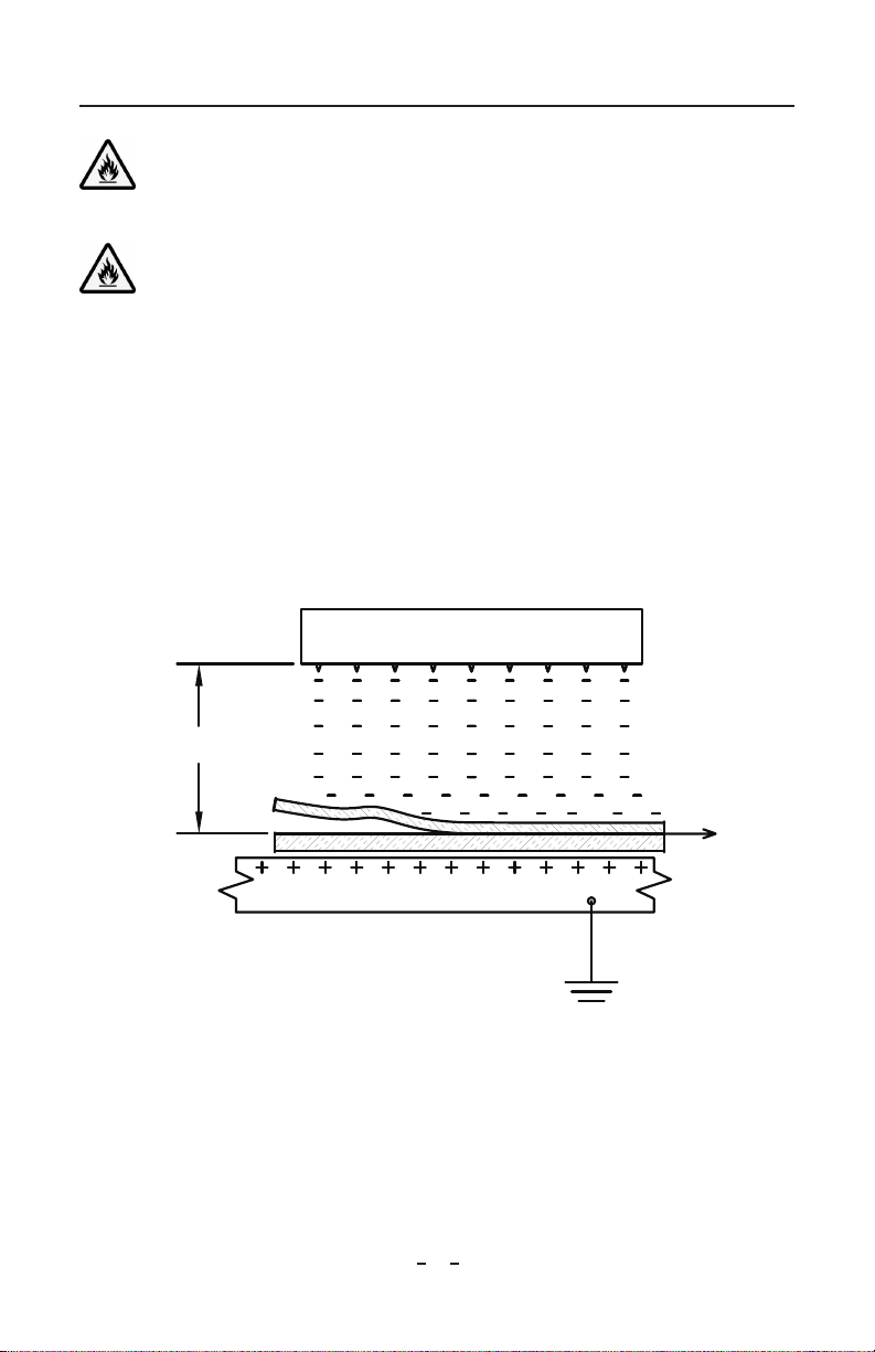
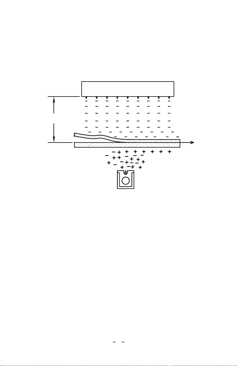
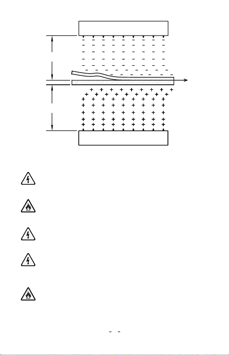
(up to 30 kV) for operation. This system is used to produce electrostatic adhesion for
temporarily bonding or pinning materials. The success of the process depends on the
insulating qualities of the material being charged, the distance to ground, distance between
bars, cleanliness, ion pin sharpness and the applied voltage. Good insulators, such as
plastic films, work particularly well with this process.
Eight rows of ionizing pins enable the Superbar to produce more ionization and afford
higher pinning action than conventional charging bars. The locations of the ionizing pins
on the charging bar are divided into two sections. Each row consists of four sets of pins.
Pin alignment for both sections is staggered to increase the effective pinning area.
Pinner Superbars are resistor-limited to provide arc-resistant operation. It is this
advancement that prevents hard arcs from occurring resulting in several improvements
when compared to traditional charging equipment:
• Increasedvoltageconsistencyandcontinuouspinningaction
• ReducedEMI/RMIthatcandisturbsensitiveelectroniccomponents
• Limitedenergyreleasethatcouldotherwisedegradesomeplasticsandother
materials causing additional damage and failures
CAUTION – Personal Injury Hazard. Pins are very sharp, be careful when
handling Superbars.
Receipt of equipment:
1. Carefully remove the equipment from its carton.
2. Inspect contents for damage that may have occurred during shipment. If any
damage has occurred, the local carrier should be notified at once. A report should be
forwarded to Simco-Ion, 2257 North Penn Road, Hatfield PA 19440, and (215) 822-
6401.
3. Empty the carton to ensure that small parts are not discarded.
Return Shipments:
Prior to returning goods, contact a Simco-Ion Customer Service Representative for a
Return Authorization Number. This number should be included on the packing list. All
correspondence should also reference the Return Authorization Number. Any item being
returned should be shipped prepaid and packed to provide adequate protection.

3
Chargemaster Pinner Superbar 5101167 Rev. F
3. SPECIFICATIONS
Ionizing Points 80 Mohm Resister limited, Spaced 5/8” between points per row,
Removable and replaceable for easy maintenance
Operating Voltage +/- 30 kV max
Operating Temperature 0-170˚F (-5 to 77˚C), 110˚F (43˚C) max ambient temperature
Operating Humidity 70% RH max, no dewing permissible
High Voltage Cable 50 kV rated irradiated polyethylene cable with fire retardant silicone
protective tubing. 10’ standard length (1/2” min bend radius)
Pin Current 375 uA (30 kV short circuit), Point to ground short, no damage, 3
second max (30 kV)
Dimensions 1 ¼” H x 6 ½” W x 14 ¼” L; effective Pinning Length: 10 ½”
Enclosure Glass filled polyester, rugged, impact resistant red color
Weight 5 ½ lb
Pinner Superbars are easy to setup, safe to use and produce superior bonding. They are
supplied with mounting hardware and are available with either straight or right angle
high voltage cable connections. The cable is enclosed within flame-resistant, flexible
silicone tubing that provides superior abrasion resistance. The ionizing pins are mounted
in sockets and can be replaced when the pins become dull.

4
Chargemaster Pinner Superbar 5101167 Rev. F
4. INSTALLATION
CAUTION – Fire Hazard
Do not install or operate equipment in close proximity to any flammable solvents
or flammable materials.
CAUTION – Fire Hazard
Do not exceed 30 kV supply voltage.
Determine Superbar Location
1. Charging Bar with Grounded Surface – In Figure 1, the charging bar faces a
production fixture that moves beneath the charging bar (alternatively the bar could
move over the fixture). After the materials to be pinned together are positioned on the
fixture, it moves beneath the charging bar. The negative ions created by the bar are
driven toward the grounded metal fixture by an electric field formed between them.
The top material blocks ion travel through the field and becomes electrostatically
charged, resulting in adhesion between the two materials and the fixture. This
arrangement emulates an interleaving application where paper or film is pinned to
metal prior to cutting and stacking.
Pinner Superbar (-)
1.5" Min.
Figure 1

5
Chargemaster Pinner Superbar 5101167 Rev. F
2. Charging Bar with Static Neutralizing Bar – In Figure 2, the charging bar faces an
insulative film while a static neutralizing bar faces an insulative sheet of material on
the opposite side (glass plastic, light particle board, etc.). As the two materials to be
pinned together pass between the bars, the negative ions created by the charging bar
charge the film, while the static neutralizing bar attempts to eliminate the apparent
charge on the sheet. This deposits a positive charge on the lower sheet. The use of
the static neutralizing bar dramatically improves the electrostatic pinning adhesion
between the two materials.
AC
Pinner Superbar (-)
1.5" Min.
Figure 2
3. Two Charging Bars – In Figure 3, one charging bar faces another of opposite
polarity in an application where decorative sheets are pinned to heavy particleboard
prior to laminating. As the materials move between the charging bars, the opposite
polarity ions created by each bar are driven toward each other by an electric field
formed between them. The decorative sheets block ion travel through the field and
become electrostatically charged. With this arrangement, the voltage differential
between the charging bars can be substantial. The sizeable voltages cause higher
levels of electrostatic adhesion. This method of charging materials is generally used
in the most difficult pinning applications. Dual polarity BP-series power supplies are
designed for applications like this.

6
Chargemaster Pinner Superbar 5101167 Rev. F
Pinner Superbar (+)
Pinner Superbar (-)
1.5" Min.
1.5" Min.
Figure 3
Mount Superbars
CAUTION – Electrical Shock Hazard
Turn power supply OFF and discharge mounting hardware before touching the
Superbar or its high voltage cable.
CAUTION – Fire Hazard
Do not install or operate equipment in close proximity to any flammable solvents
or flammable materials.
CAUTION – Electrical Shock Hazard
Only qualified service personnel are to perform installation tasks.
CAUTION – Electrical Shock Hazard
It is essential that the machine frame, and all metal parts in the vicinity, be
grounded either through well-grounded electrical conduit or by heavy copper wire
connecting the frame to a water pipe.
CAUTION – Fire Hazard
Do not exceed 30 kV supply voltage. Use Superbar with Simco CH30, BP30 or
KNH34powersupplyONLY.

7
Chargemaster Pinner Superbar 5101167 Rev. F
NOTE – Do not exceed the 5.0 mA current capacity of the power supply.
NOTE – Do not install bars face-to-face less than 3” apart.
NOTE – Do not operate bars continuously for more than twenty minutes when
equipment is not operating. A photoelectric sensor with a signal OFF delay timer
should be used to disable the power supply when no product is traveling between
the bars. Energize the bar when the photoelectric sensor senses product flow.
Position the sensor upstream of the bars and set the OFF delay timer to 3 minutes
andconnectthenormallyopencontactoftheOFFdelaytimertotheremoteON/
OFF terminal strip located on the rear of the power supply.
1. Determine the best location for the Pinner Superbar using the above applications
for guidance. For optimum performance, bars should be positioned away from all
ground references as shown in Figure 4.
1" from rear
2.5" from sides
1" from ends
1.5" from front
(3.0" if two
bars mounted
face-to-face)
Figure 4
2. Drill clearance holes in an insulating support frame (e.g., fiberglass, phenolic, delrin,
nylon,PVC)toaccommodatethebar’s1/4”mountingbolts.
3. Inserttheheadofeach5/16”nonconductiveboltintothekeyholeslotintherearof
the charging bar and secure to each mounting rod (see Figure 5).

8
Chargemaster Pinner Superbar 5101167 Rev. F
4. Secure the mounting rods to the insulating support frame using 1/4” fasteners
provided.
5. Set the height, if necessary, by cutting the end of each mounting rod (see Figure-5).
Assure that the bar is parallel to the target material surface.
6. Tighten all nuts with a wrench after verifying the position and spacing between bars
and ground references. Refer to Figures 1-4 for minimum recommended spacing.
Figure 5
Install High Voltage Cables
CAUTION – Electrical Shock Hazard
Ground all surrounding metal parts in the vicinity of the charging bar.
CAUTION – Fire Hazard
Do not install or operate equipment in close proximity to any flammable solvents
or flammable materials.
1. Route the high voltage cable for each charging bar along the machine frame or wall
to the power supply. Assure the cable is safely away from all moving parts and sharp
edges.
2. Verify that the high voltage cables are run separately from any control cables
associatedwithotherelectronicequipment.TheEMIfromhighvoltagecablesmay
interfere with the operation of sensitive electronic equipment.
3. Assure that the power supply is de-energized and turned off.

9
Chargemaster Pinner Superbar 5101167 Rev. F
CAUTION – Electrical Shock Hazard
Turn off power supply before connecting or disconnecting the high voltage cable.
4. Insert the cable (with spring loaded connector attached) into the power supply high
voltage connection. Screw in the knurled plug to secure the cable. NOTE – FINGER
TIGHTENONLY.
Install Optional Mounting Bracket (5051494)
CAUTION – Electrical Shock Hazard
Ground all surrounding metal parts in the vicinity of the charging bar.
CAUTION – Fire Hazard
Do not install or operate equipment in close proximity to any flammable solvents
or flammable materials.
1. The Optional Mounting Bracket is designed to fit the inside frame-to-frame
dimension on standard incline feed stackers. Position the assembled bracket between
the drive belt support idlers (see Figure 5A) with Super Pinner Bars set to maximum
open position (full up/down), centering the drive belts between the Super Pinner
Bars,andclampbracketinposition.Marktheframeformountinghole(2-5/16”)
requirements on each side frame.
2. Remove mounting bracket assembly and drill holes in side frames. Secure mounting
bracket using 5/16” carriage bolts provided. Reset the Super Pinner Bars to 3”
separation, being sure to keep the drive belts centered between the static bars.
3. Route the high voltage cable for each charging bar along the machine frame or wall
to the power supply. Assure the cable is safely away from all moving parts and sharp
edges.
4. Verify that the high voltage cables are run separately from any control cables
associatedwithotherelectronicequipment.TheEMIfromhighvoltagecablesmay
interfere with the operation of sensitive electronic equipment.
5. Assure that the power supply is de-energized and turned off.

10
Chargemaster Pinner Superbar 5101167 Rev. F
CAUTION – Electrical Shock Hazard
Turn off power supply before connecting or disconnecting the high voltage cable.
1. Insert the cable (with spring loaded connector attached) into the power supply high
voltage connection. Screw in the knurled plug to secure the cable. NOTE – FINGER
TIGHTENONLY.

11
Chargemaster Pinner Superbar 5101167 Rev. F
5. OPERATION
NOTE – Do not operate bars continuously for more than twenty minutes when
equipment is not operating. A photoelectric sensor with a signal OFF delay timer
should be used to disable the power supply when no product is traveling between
the bars. Energize the bar when the photoelectric sensor senses product flow.
Position the sensor upstream of the bars and set the OFF delay timer to 3 minutes
andconnectthenormallyopencontactoftheOFFdelaytimertotheremoteON/
OFF terminal strip located on the rear of the power supply.
NOTE – Do not operate bars face-to-face less than 3” apart.
CAUTION – Electrical Shock Hazard
Do not touch Charging Bar during operation.
CAUTION – Fire Hazard
Do not operate equipment in close proximity to any flammable solvents or
flammable materials.
1. Before energizing any power supply:
• Ensurethatallpowersuppliesareproperlygrounded.
• Ensurethatallchargingbarshavebeenproperlylocated,positionedandinstalled.
• Ensureallrequirementsprintedintheapplicablepowersupplyinstructionshave
been fully complied with.
2. After the above checks have been performed, simply energize each power supply to
operate the charging bars.
3. Setting Strength of Pinning:
• Decreasepowersupplyvoltagetozerobeforeorduringpower-updependingon
power supply model.
• Slowlyincreasevoltageuntilpinningactionisobserved,thenincreasesetting
10% to allow for variation in conditions.
• Ifconditionschangeandthechargingbarisoperatinginelectricalstress
condition (evident by purple glow on pins and slight sizzling noise), slowly
decrease operating voltage of the power supply.
• Ifconditionschangeandadhesionorpinningstrengthisnotadequate,slowly
increase operating voltage of the power supply.
NOTE – Do not exceed the 5.0 mA current capacity of the power supply.

12
Chargemaster Pinner Superbar 5101167 Rev. F
NOTE – Sustained operation in electrical stress will likely interfere with operation
of the charging system. Electrical stress reduces output voltage from the power
supply and suppresses the charging process. Sustained stressed operation may
also damage the bar and power supply.
Always turn the power supply OFF when the system is not in use. For safety and ease
of operation, it is recommended to connect the power supply line cord to the electrical
system of the machine in such a manner that the power supply is only energized when the
machine is in operation.

13
Chargemaster Pinner Superbar 5101167 Rev. F
6. TROUBLESHOOTING
NOTE – Only qualified service personnel are to perform troubleshooting tasks.
1. Troubleshooting electrical stress observed between Charging Bar and the target
material:
• Electricalstresscanoccurbetweenthebarandagroundreferencebeneaththe
target material. This stress typically occurs at edges of material being charged
and comes from the ion emitter points at the end of the Charging Bar. Eliminate
this stress by gradually reducing the operating voltage from the power supply.
2. Troubleshooting electrical arcing from Charging Bar to machine frame:
• Ifelectricalstressoccursbetweenthebarandframememberonwhichthebar
is mounted, the bar may be improperly mounted. Verify that all equipment has
been properly mounted and grounded.
• Ifelectricalstressoccursfromtheendofthebartothesideframeofthe
machine, slide the bar away from the side frame if possible. If it is not possible
to do this, it may be necessary to install an arc shield, please call your Simco
representative for more details.
3. Troubleshooting low pinning strength:
• Ifpinningstrengthisnotadequateandthepowersupplyisalreadyatmaximum
output voltage, moving the bar closer to the target material can increase pinning
strength. Reduce the bar-to-material distance until pinning strength is adequate.
At this new distance, it may be necessary to adjust the operating voltage of the
power supply.
NOTE – Do not exceed the 5.0 mA current capacity of the power supply.
• Lowpinningstrengthmayalsobeduetoerosionoftheemitterpoints.Sharp
points promote the best ionization of air molecules. Inspect the emitter points, if
they are visibly eroded or corroded follow these steps:
• Removecontaminationbybrushingtheemitterpinswithanonmetallicbrush.
• Ifacceptableperformanceisnotrestoredaftercleaning,thepinsofthePinner
Superbar should be replaced. Remove existing emitter pins using needle-nose
pliers and replace with new pins in each socket.
• Ifacceptableperformanceisnotrestored,contactSimco-IonCustomerServiceat
(215) 822-6401.

14
Chargemaster Pinner Superbar 5101167 Rev. F
7. MAINTENANCE
NOTE – Only qualified service personnel are to perform maintenance tasks.
CAUTION – Electrical Shock Hazard
De-energize all power supplies before performing any maintenance tasks.
Cleaning Charging Bars
1. DAILY: Dust or dirt around the emitter pins will reduce the effectiveness of
the Pinner Superbar. The bar should be cleaned daily to prevent deposits from
accumulating. Use the cleaning brush supplied with the bar and then blow off with
clean, dry compressed air to remove loose particulate.
NOTE – Never scrape emitter pins with hard or sharp objects that may damage their
points.
2. EVERYTWOWEEKS: Wipe all exterior surfaces of the bar, mounting hardware,
and insulated support frame using a clean soft cloth. If necessary, dampen the
cloth with isopropyl alcohol to remove inks, conductive contaminants, or resistant
coatings.
CAUTION – Fire Hazard
Ensure all traces of alcohol have been removed and the static bar is completely
dry before energizing the power supply.
NOTE – The alcohol must not contain additives. Never use harsh solvents such as
lacquer thinner, naphtha or acetone; they will attack the bar housing material.
NOTE – Do not pour alcohol directly onto the bars, and do not soak the bar or any
of its components in alcohol.
3. EVERY THREE MONTHS: Replace ionizing pins that have become dulled (see
Step-B below).
Replacing Ionizing Pins
NOTE – Only qualified service personnel are to perform maintenance tasks.
CAUTION – Electrical Shock Hazard
De-energize all power supplies before performing any maintenance tasks.

15
Chargemaster Pinner Superbar 5101167 Rev. F
1. A dull or eroded point of an ionization pin causes its pinning strength to decrease.
Sharp points promote the best ionization. It is recommended that ionization pins be
replaced after no more than three months of service.
2. Visually inspect ionizing pinpoints for corrosion.
3. Remove all corroded pins from their sockets using needle-nose pliers.
4. Insert new ionizing pins back into their sockets.
Replacing HV Connectors
NOTE – Only qualified service personnel are to perform maintenance tasks.
CAUTION – Electrical Shock Hazard
Turn off power supply before connecting or disconnecting the high voltage
cable.
1. Loosen the setscrew of the spring-loaded terminal using a 5/64” hex key or allen
wrench.
2. Remove the high voltage connector from the cable and replace with the correct high
voltage connector.
3. Assure that the conductor of the high voltage cable is fully inserted into the spring-
loaded terminal of the new high voltage connector by completely removing the
setscrew from the threaded hole to allow viewing of the conductor through the hole.
4. Hold the cable firmly in place when the conductor of the high voltage cable is visible
through the threaded hole.
5. Carefully tighten the setscrew onto the conductor once the holes of the spring-loaded
terminal and insulating tube are properly aligned.

16
Chargemaster Pinner Superbar 5101167 Rev. F
8. WARRANTY
SIMCO-IONwarrantsitsproductstobefreeofdefectsincomponents,workmanship,or
materials for a period of one year from date of purchase. This warranty does not apply
to any physical or electrical damage caused by misuse, abuse or negligence (such as any
modifications made to the unit or service work done by any other than SIMCO-ION
authorized technicians). Any unit with altered or removed serial number is ineligible for
warranty.
SIMCO-ION will not be liable for loss or damage due directly or indirectly to an
occurrence or use for which the product is not designed or intended. In no event shall
SIMCO-ION be liable for incidental or consequential damages except where state or
regional laws override.
This warranty extends to the original purchaser and is not transferable. No person, agent,
distributor, dealer or company is authorized to change, modify, or amend the terms of this
warranty in any manner whatsoever.
All products returned must have an “RA” (Return Authorization) number regardless of
warrantystatus.CallSIMCO-IONforanassignedRAnumber.
Information in this document is subject to change without notice and does not represent
acommitmentonthepartofSIMCO-ION.Nopartofthismanualmaybereproducedor
transmitted in any form or by any means, electronic or mechanical, including photocopying
and recording, for any purpose other than the purchaser’s personal use without written
permissionofSIMCO-ION.

17
Chargemaster Pinner Superbar 5101167 Rev. F
(This page intentionally left blank.)

Chargemaster Pinner Superbar 5101167 Rev. F
Simco-Ion
2257 North Penn Road
Hatfield, PA 19440
(215) 822-6401
(800) 203-3419
www.simco-ion.com
© 2014 Simco-Ion. Printed in the U.S.A.
Table of contents
Other ITW Power Supply manuals

ITW
ITW Simco-Ion S165S User manual

ITW
ITW SIMCO ION IQ Power BPS-C User manual

ITW
ITW Simco-ion IQ Power MPS User manual

ITW
ITW Simco-Ion D167Q User manual

ITW
ITW Orbitalum ORBIMAT 165 CA User manual

ITW
ITW Simco-Ion Chargemaster VCM30 Series User manual

ITW
ITW SIMCO ION D Series User manual

ITW
ITW Simco-Ion IQ Power HL User manual

ITW
ITW Simco-Ion Dual Phase+ User manual