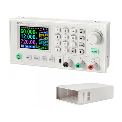
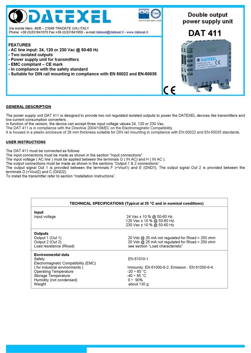
Datexel DAT 5030 IS/A User guide

INSTRUCTIONS DAT 5030 IS ATEX
INSTALLATION, MAINTENANCE and USE
ATEX
INTRODUCTION
Hereafter are reported the safet instructions for use of
DATEXEL Associated Apparatus , in compliance with the
European standard 2014/34/EU (ATEX).
Read carefull these instructions before to install or test
the following devices:
DAT 5030 IS /A
DAT 5030 IS /AH
DAT 5030 IS /B
DAT 5030 IS /BH
DESCRIPTION
The Associated Apparatus DAT 5030 IS /A, DAT 5030 IS /AH, DAT 5030 IS /B and DAT 5030 IS /BH are designed and manufactured
by DAT X L Srl, Tradate (VA) in compliance with the ssential Health and Safety Requirements defined by the Directive 2014/34/ U
(AT X), Group II, Category (1) G D.
In compliance with the Standards N 60079-0 : 2012 / A11 : 2013, N 60079-11 : 2012, N 60079-26 : 2015.
C RTIFICAT NUMB R:
CESI 04 ATEX 095
MARKING
PROT CTION MOD :
[Ex ia Ga] IIC / [Ex ia Da] IIIC
Associated Apparatus,
categor "ia", group "IIC", for installation in safe area.
AT X COD :
nr. Notified Body charged of surveillance on production (CESI)
Group II (surface installations)
Category 1 apparatus (associated apparatus)
Explosive atmosphere of gases, vapours and mists
Explosive atmosphere of dusts
0722
II
(1)
G
D
0722
Page 1 of 3
II (1) G
II (1) D

Intrinsicall safe specifications:
ELECTRICAL CHARACTERISTICS
Operative temperature:
Ta : -20 ÷ +60 °C
SAFETY INSTRUCTIONS FOR INSTALLATION, USE and MAINTENANCE
The installation and maintenance of DAT X L Associated Apparatus must be made in compliance with the Standards relative to electric
installations in hazardous areas. Before install the device, read carefully the relative instructions sheet and respect the following standards:
Hazardous areas with GAS atmosphere and Combustible Dust (not mines)
- Standard EN 60079-14 (current edition) for choice and installation of the equipments.
- Standard EN 60079-25 (current edition) for intrinsicall safe S stems.
(note: ever "t polog " of Ex i s stem must be described in a "S stem description" document ).
- Standard EN 60079-17 (current edition) for check and maintenance.
To guarantee a correct and safe operation of devices, respect the following requirements:
1) All devices connected to the output and power suppl terminals and to rela s must be subjected at a maximum voltage of
250 Vrms (Um). The power suppl voltage value must be included between 20 and 30 Vdc.
2) The devices must be installed in a SAFE AREA or in hazardous area if them have been closed in an explosion proof enclosure.
Moreover , it is necessar to connect the devices in applications that guarantee them a minimum grade of protection
IP20 for internal places, or IP54 for external places.
3) Repair of devices and substitution of protections must be executed onl b DATEXEL s.r.l.
Page 2 of 3
Um = 250 V
Uo
Io
Po
=
=
=
Terminals J-I; A-B-C-D :
Terminals 4-6:
Uo
Io
Po
Lo
Co
=
=
=
=
=
26.4 V
93 mA
615 mW
4.2 mH
75 nF
Terminals 6-5:
Ta : -20 ÷ +60 °C
Ui
Ii
Pi
Li
Ci
=
=
=
=
=
30 V
100 mA
0.75 W
~ 0 mH
12 nF
Ui
Ii
Pi
Li
Ci
=
=
=
=
=
30 V
100 mA
0.75 W
~ 0 mH
12 nF
1.2 V
46 mA
14 mW
Terminals J-I; A-B-C-D; O-P-Q-R : Um = 250 V
Uo
Io
Po
=
=
=
1.2 V
46 mA
14 mW
Terminals 4-6; 14-16:
Uo
Io
Po
Lo
Co
=
=
=
=
=
26.4 V
93 mA
615 mW
4.2 mH
75 nF
Terminals 6-5; 16-15:
Ta : -20 ÷ +60 °C
Ui
Ii
Pi
Li
Ci
=
=
=
=
=
30 V
100 mA
0.75 W
~ 0 mH
12 nF
Ui
Ii
Pi
Li
Ci
=
=
=
=
=
30 V
100 mA
0.75 W
~ 0 mH
12 nF
DAT 5030 IS /A (single channel)
DAT 5030 IS /AH (single channel + HART)
DAT 5030 IS /B (double channel)
DAT 5030 IS /BH (double channel + HART)
V
I
26.4 V
93 mA
Load characteristic
Terminals 4-6 and 14-16:
NOTE: The electrical parameters on terminals 6-5 and 16-15 are
within the limits defined in the par. 5.7 of the standard EN 60079-11
relative to "Simple Apparatus".

Datexel s.r.l. reserves its right to modify all or in part the characteristics of its products without warning at any time.
Via monte Nero, 40/B – 21049 Tradate (VA) Italy - Phone: +39 (0)331841070 Fax:+39 (0)331841950 - e-mail:[email protected] - www.datexel.it
The device DAT 5030 IS operates as a power supplier and isolated repeater of 0÷20 and 4÷20mA current loop both active and passive.
The input signal coming from an hazardous area (ZON 0,1 or 2) is isolated, converted and provided in a safe area as a voltage (up to
10V) or current (up to 20 mA) signal. The model ' DAT 5030 IS /A ' is a single channel repeater; the model 'DAT 5030 IS /B' is a double
channel repeater: it can be used also as signal doubler, connecting in series the inputs of two measure channel.
The models DAT 5030 IS /AH and DAT 5030 IS /BH are able to transfer an HART signal between input and output .
APPLICATION NOTES
All devices make a galvanic isolation between input and
output; this is necessary when the sensor has not a
right isolation to the ground.
All device are designed for mounting on DIN rail.
In a Intrinsically Safe system it is necessary to verify
that the maximum energy available in the circuit will be
lower than the ignition value of the explosive mixture.
It occurs to verify specifically that:
- The intrinsically safe equipments and the associated
apparatus must be qualified for the employ in the
hazardous zone which them have been connected
(category, type of gas, etc..).
- The values Ui, Ii and Pi of an equipment must be
respectively equal o greater than the maximum values
Uo, Io and Po of equipments which it has been
connected.
- The sum of equipments equivalent capacity (Ci) and
connecting cable capacity (Cc) must be lower than the
admitted capacity (Co) of the equipment which them
have been connected.
- The sum of equipments equivalent inductance (Li) and
connecting cable inductance (Lc) must be lower than
the admitted inductance (Lo) of the equipment which
them have been connected.
Two wires connection
Three wires connection
SI_ED.010117
Ui > Uo (Ci) + Cc < Co
Ii > Io (Li) + Lc < Lo
Pi > Po
Page 3 of 3
Intrisically Safe
equipment
(transmitter)
HAZARDOUS AREA
(ZONE 0, 1 or 2)
SAFE AREA
(ex. control room )
Co
Lo
Uo
Io
Po
DAT 5030 IS
Ci
Li
Ui
Ii
Pi Cc
Lc 4
6
Intrisically
Safe
equipment
( transmitter)
HAZARDOUS AREA
(ZONE 0, 1 or 2)
SAFE AREA
(ex. control room)
Co
Lo
Uo
Io
Po
DAT 5030 IS
Ci
Li
Ui
Ii
Pi Cc
Lc
4
6
5
Doubler signal connections
Intrisically
Safe
equipment
(transmitter)
HAZARDOUS AREA
(ZONE 0, 1 or 2)
SAFE AREA
(ex. control room)
Co
Lo
Uo
Io
Po
DAT5030 IS /B
Ci
Li
Ui
Ii
Pi
Ci
Li
(Simple App.)
15
16
4
6
Cc
Lc
This manual suits for next models
3
Other Datexel Power Supply manuals