ETC Installation Guide
Paradigm Network Station Power Supply
Corpora te He adqua rte rs nMiddleton, WI, USA |+1 608 831 4116
Globa l Offic es nLondon, UK |Rome, IT |Holzkirchen, DE |Paris, FR |Hong Kong
Dubai, UAE |Singapore |New York, NY |Orlando, FL |Los Angeles, CA |Austin, TX
We b etcconnect.com |Support support.etcconnect.com
Conta c t etcconnect.com/contactETC |© 2021 Electronic Theatre Controls, Inc.
Trademark and patent info: etcconnect.com/ip |Product information and specifications
subject to change. ETCintends this document to be provided in its entirety.
7182M2100 Rev A Released 2021-08
Overview
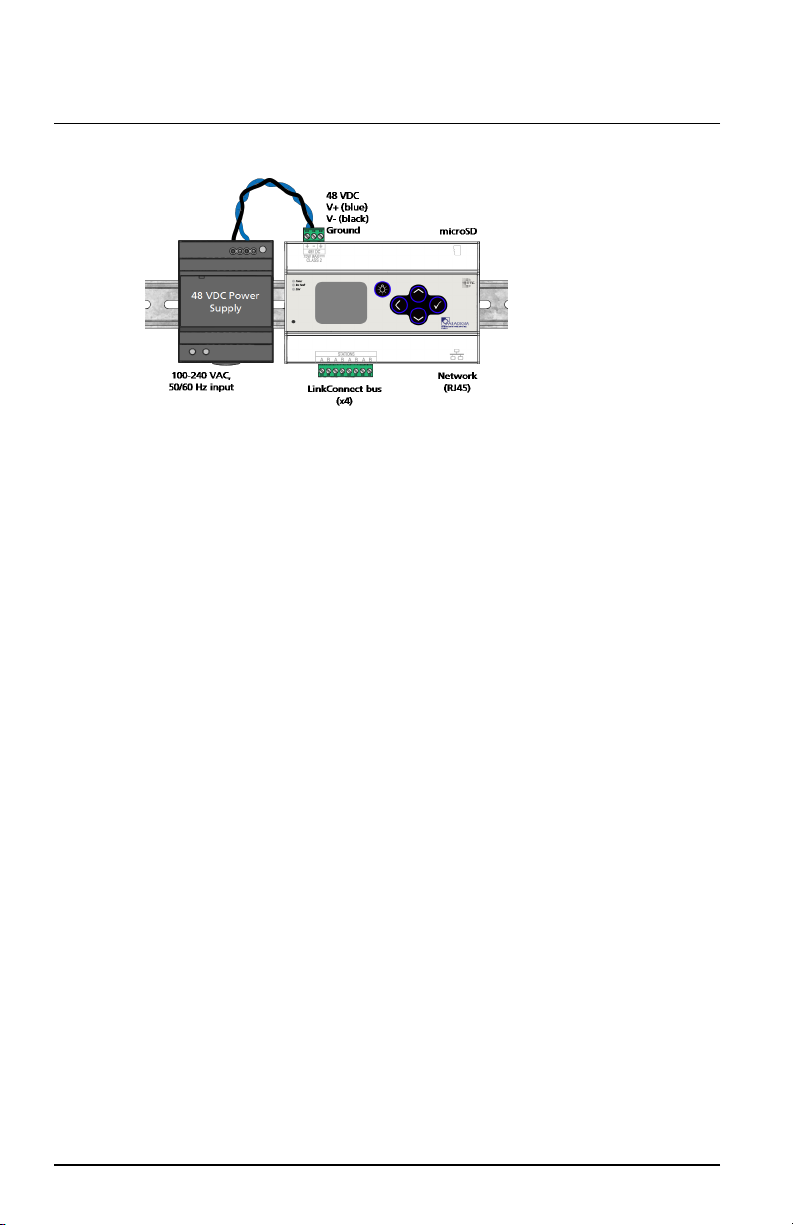
The Network Station Power Supply
(P-NSPS-D) is a DIN rail mounted
power supply that powers up to
63Paradigm stations or sensors over
the LinkConnect station
communication bus.
The Network Station Power Supply
consists of two components that must
be used together:the DIN rail Network Station Power Supply that powers the
station communication bus, and the DIN rail 48 VDC Power Supply that feeds
the DC power to it. This guide covers installation and basic setup of both
products.
Specifications
Note:
Installation must follow all national and local codes for
electrical equipment.
Environment
Ambient 0°C-50°C (32°F-122°F), 0-95% relative humidity (non-condensing)
Mounting
Vertically mount (only) on horizontal DIN rail (TS35 compatible).
Clearance
For best performance and to prevent overheating, leave a minimum clearance
between devices on the DINrail. Clearance required: adjacent - 15mm
(0.6in), above 40 mm (1.6 in), below20mm(0.8in).
Important Safeguards
CAUTION:
For use in a controlled environment.
ATTENTION :
Pour une utilisation dans un environnement
contrôlé.