Datexel DAT1112 User manual

FEATURES
Input for E, J, K, N, S, R, B e T thermocouple type
Two wire 4÷20 mA voltage linear output
Zero and span programmable by DIP SWITCH
Good accuracy and performance stability
Programmable for both°C & °F scales
One model covers both K & J TC type.
Conform to EMC standards - CE mark
Suitable for mounting on DIN B connection heads
Low profile
Low cost
APPLICATIONS
Temperature monitoring and controlling in:
- Process controls
- Automation systems
- Energy sources management
GENERAL INFORMATION
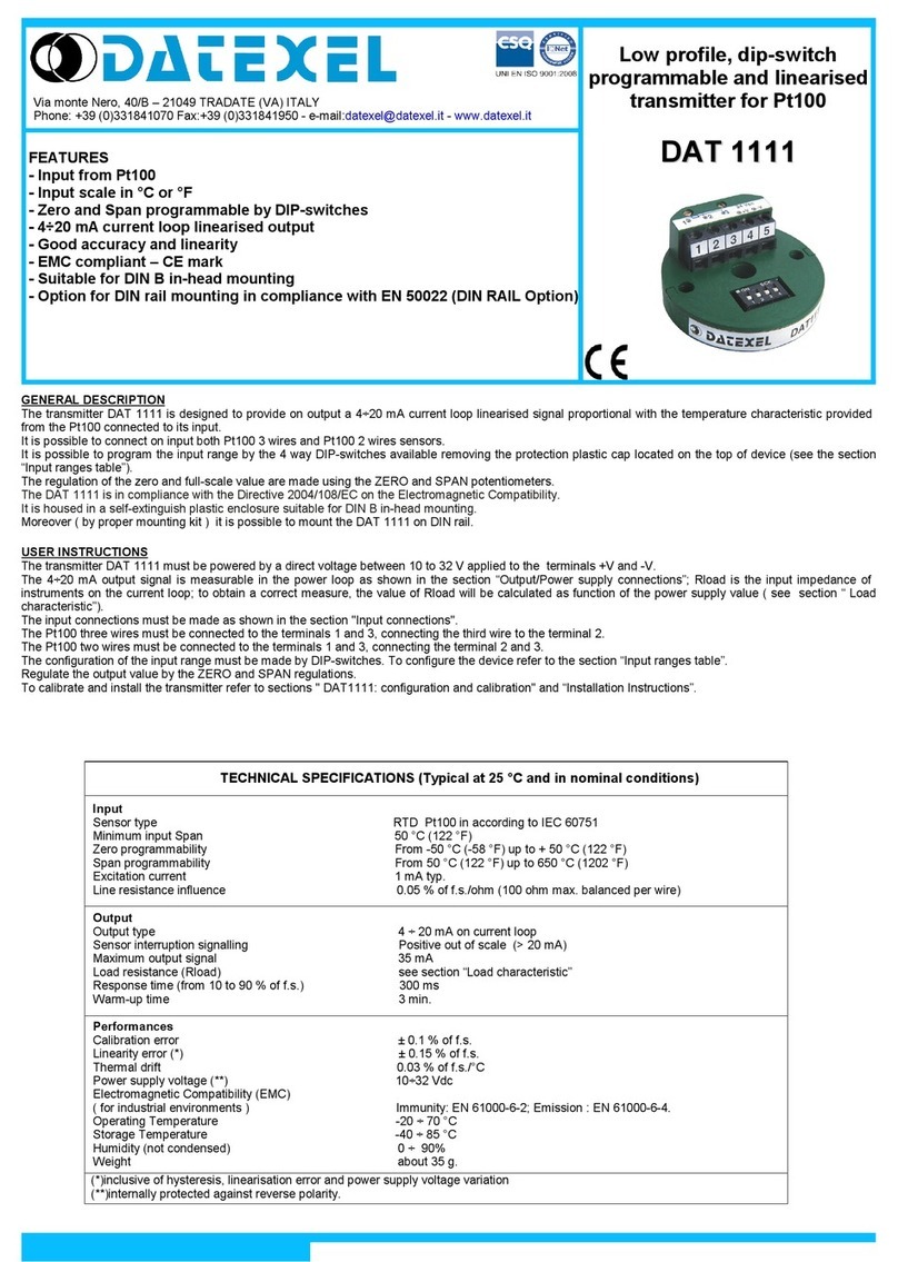
The two wire DAT1112 transmitter has been designed to give an output current signal of 4÷20 mA; this signal is perfectly linear and
proportional to the voltage generated by the thermocouple sensor connected to its input. The output current signal is supplied on the
same two wires used to power the device.
The user can program the full scale easily and quickly by means of four way DIP switch. The "zero" value can be varied between
-50°Cto+50°C or-100 to+100 °Fand thespan valuecan beprogrammed followingTC limitsonly.Moreover the samemodel issuitable
forKand Jthermocouple,so asanothermodel issuitablefor RandS thermocouple. Themaximumaccuracy andreliabilityare ensured
for all the functions (conditioning, cold junction compensation and current transmission) thanks to the employement of high precision
and high-quality components and to the use of the SMD technology. The device, conform to the 89/336/EEC directives on
electromagneticcompatibility,ishousedina ruggedself-extinguishing plasticcasesuitablefor direct mountingontheconnectionhead.
TECHNICAL SPECIFICATIONS (Typical @ 25°C and in the nominal conditions)
Input
Type of sensor TC type K, J, S, N, E, T, B and R according to SIPT68
Zero Programmable in the -50°C to +50°C range or -100°F to 100°F range.
Span Programmable according to the "version table".
Influence of line resistance 0,2 µV /
Output
Sensor interruption signaling Positive out of scale (< 3.5 mA on request)
Measuring current 4÷20 mA, two wires
Current limitation about 35 mA
Protection against polarity reversal 60 V reverse max
Response time ( 10 to 90% of full scale) 0.3 s.
Warm-up time 3 minutes
Performances
Calibration inaccuracy ± 0.1% of f.s. or ± 0.2°C
Linearity error (inclusive of hysteresis and supply ± 0.1% of full scale
voltage variations)
Electromagnetic Compatibility (EMC) According to EN50081-2 and EN50082-2
Thermal drift 0.02% of full scale/°C ( for span >= 300 °C / 500 °F )
Power supply voltage 12 ÷ 32 V
Operating temperature - 20 ÷ 70 °C
Storage temperature - 40 ÷ 100 °C
Relative humidity (non-condensing) 0 ÷ 90 %
Weight 25 grams
DAT 1112
Programmable range transmitter
for thermocouple

LOAD CHARACTERISTICS
WIRING DIAGRAM
WORKING DIAGRAM
HOW TO ORDER:
DAT 1112 - 1
The transmitter must be powered with a voltage ranging from 12 to 32 V, applied between the -V and +V terminals.The
permissible Rload resistance, equivalent to that of the instruments applied in series to the voltage generator, must be
determinedasafunctionofthepowersupplyvoltagevalueandaccordingtotheloadcharacteristicsothatitsvalueiscovered
bytheworkingarea.DAT1112isavailablein6differentversions,coveringallcommonsensorstypes.Formostusedsensors
asingleunitcover2sensors,allowingsubstantialreductionofstocks.For programming the device, see the technical sheet
" DAT 1112 Programming Instruction ". Once the device is programmed, the calibration is carried out by adjusting the zero
and the span potentiometer as follows: apply a signal corresponding to desired minimum input signal and than adjust the
zeropotentiometertogetIout=4,00mA.Applyasignalcorrespondingtodesiredmaximuminputsignalandthanadjust the
span potentiometer to get Iout = 20,00 mA. Repeat these operations until the needed accuracy is obtained.
DIMENSIONS
(measures in mm.)
Version
VERSION TABLE
Version Sensor Programmable Span
1
2
3
4
5
6
K & J
R & S
E
N
B
T
100 - 1400°C / 200 - 2500°F (K)
100 - 950°C / 200 - 1800°F (J)
650 - 1760°C / 1200 - 3200°F (R)
700 - 1760°C / 1290 - 3200°F (S)
100 - 350°C / 200 - 600°F
900 - 1820°C / 1600 - 3250°F
150 - 1350°C / 250 - 2400°F
50 - 1050°C / 100 - 1900°F
MAIN
AMP.
LINEARIZER
TWO WIRE
TRANSMITTER +V
-V
1
2
- TC
+ TC
COLD
JUNCT.
COMP. INTERNAL
REFERENCE
GENERATOR
5
4
TC
RLoad
+
-V
+V
123
+
7
43 17
33
ZERO SPAN
ON
1
8
OPERATING INSTRUCTIONS

-
Version 1 (thermocouple K & J):
Sensor selection:
Sensor K: SW1 ON
Sensor J: SW1 OFF
200 to 270°F
100 to 150°C
270 to 520°F
150 to 390°C
520 to 920°F
920 to 2500°F
390 to 510°C
510 to 1400°C
OFF
ON
ON ON
ON
Sensor
OFF OFF
OFF
200 to 210°F
520 to 700°F
700 to 1700°F
210 to 520°F
SPAN PROGRAMMING
Sensor Range SW4 SW2
390 to 950°C
100 to 115°C
115 to 290°C
290 to 390°C
ON
ON ON
ON
OFF
OFF
OFF
OFF
J
K
T
R
S
DAT1112 PROGRAMMING INSTRUCTIONS
- Version 2 (thermocouple R & S):
-Version 3 (thermocoupleT):
Sensor selection:
Sensor
K & J Range
-50 to -10°C
-10 to 50°C
15 to 100°F
-100 to 15°F
SW3
ON
ON
OFF
OFF
ZERO PROGRAMMING
SPAN PROGRAMMING
Range SW4 SW2
It is not necessary because the transmitter is able to operate either with the thermocouple R or
the thermocouple S.
It is not necessary. Zero could be adjusted from -50°C up to 50°C by the appositely dedicated
ZERO adjusting potentiometer.
It is not necessary. Zero could be adjusted from -50°C up to 50°C by the appositely dedicated
ZERO adjusting potentiometer.
1290 to 1850°F
1850 to 3200°F
1010 to 1760°C
700 to 1010°C
ON
ON
ON OFF
OFF
OFF OFF
OFF
1200 to 1720°F
1720 to 3200°F
SPAN PROGRAMMING
ZERO PROGRAMMING:
ZERO PROGRAMMING:
Sensor Range SW1 SW2 SW3 SW4
650 to 940°C
940 to 1760°C
ON
ON ON
OFF OFF OFF
OFF
OFF
210 to 290°F
280 to 840°F
SPAN PROGRAMMING
Sensor Range SW4 SW3 SW2 SW1
100 to 145°C
140 to 450°C
ON
ON ON
OFF OFF OFF
OFF
OFF

EDIT.07.03-REV.00
DATEXEL S.r.l. - Via Oslavia, 21- 21049 TRADATE (VA) ITALY - Tel 0331 - 841070 - Telefax 0331 - 841950
La società Datexel si riserva il diritto di modificare in tutto o in parte le caratteristiche dei propri prodotti senza alcun preavviso
Datexel reserves its right to modify the characteristics of its products totally or in part without warning at any time.
-Version 5 (thermocouple N):
SPAN PROGRAMMING
Sensor Range SW4 SW2
150°C to 200°C ON OFF
200°C to 480°C ON ON
480°C to 580°C OFF OFF
N
580°C to 1300°C OFF ON
ZERO PROGRAMMING
Sensor Range SW3 SW1
N-50°C to –15°C
-15°C to 50°C OFF
ON OFF
OFF
Table of contents
Other Datexel Transmitter manuals
