Maxcom MX-T1500A Series User manual

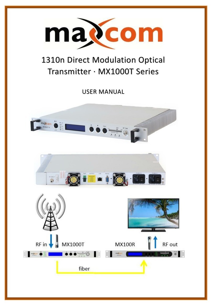
1550nm Direct Modulation Optical
Transmitter · MX-T1500A Series
U
US
SE
ER
R
M
MA
AN
NU
UA
AL
L
PRODUCT DESCRIPTION
The Maxcom MX-T1500A is a 1550nm direct modulation optical transmitter with high index and AGC
function. Maxcom incorporates a high linearity and a low chirp DFB laser, built-in pre-distortion
compensation and AGC, APC, ATC closed loop control, which improve the performance index. It may
be used in a FTTx application for transmitting Digital QAM CATV and DOCSIS RF signals over fiber.
Optimized for networks under 25km using an EDFA. This transmitter may also be ordered with
Optional WDM narrow-band laser (standard ITU wavelengths available).
•MX-T1500AC optical transmitter: Standard CATV wavelength
•MX-T1500AU optical transmitter: ITU standard DWDM wavelength
PRODUCT FEATURES
•Low chirp, high linearity DFB laser, chirp compensation.
•Dual module RF driver, highly efficient laser pre-distortion adjustment.
•Full-automatic OMI control, AGC & MGC.
•Modulation status display.
•Standard optical output is +6 dBm
•Auto temperature control to ensure long laser life.
•Commonly used in RFoG or RF Overlay networks 25km or less
www.maxcomcorp.com 209-339-2333

Transmitter Controls, Indicators, and Alarms
This section of the manual will provide an overview of the available menus in the MX-T1500A series
transmitter. All instructions in this Section refer to the representation of the front panel shown in the
diagram below. The user may scroll through the TX menus by using the push buttons that are on the
front panel.
Operation of the front panel
Open menu
A. Plug in power supply
B. Turn on power switch in the rear panel (AC units)
Front panel display “KEY OFF”
Laser Indicator lamp Red
RF Indicator lamp Red
TEMP Indicator lamp Green
POWER1 Indicator lamp Green
POWER2 Indicator lamp Green
C. Press laser start-up key switch
The front panel shows “KEY ON…”. Laser Indicator lamp will turn to green
from red when the input optic power is in the normal range and the unit
enters self-diagnostics. After performing the check, the unit will begin
operating and display: “Descriptor”.
1.1.1 Start-up main menu
Press ▲\▼button and the following menu will be displayed in sequence.
Menu # 1 - Descriptor
Read-only menu, indicates the model of this equipment
Menu # 2 - LD S/N
Read-only menu, indicates the serial-number
Menu # 3 - OUTPUT
Read-only menu, displays the optical output power in dBm

Menu # 4 - LD CURRENT
Read-only menu, displays the laser of current in mA
Menu # 5 - LD TEMP
Read-only menu, displays the laser temperature in °C
Menu # 6 - LD COOLING
Read-only menu, displays the amount of current that the Thermoelectric Cooler
requires to maintain the laser temperature at nominal 25 °C
Menu # 7 - RF MODE
Current RF mode, display AGC/MGC . If displaying RF Mode = AGC, AGC is
selected. If displaying RF Mode = MGC, MGC was selected
Menu # 8 - RF Level
Read-only menu, indicates the RF input level
Menu # 9 - UNIT TEMP
Read-only menu, indicates the system temperature
Menu # 10 - +5V Monitor
Read-only menu, displays the voltage +5V
Menu # 11 - -5V Monitor
Read-only menu, displays the voltage -5V
Menu # 12 - +24V Monitor
Read-only menu, displays the voltage +24V
Menu # 13 - IP
Adjustable feature, displays the IP address of SNMP
Menu # 14 - Sub
Adjustable list, display the address of net mask
Menu # 15 - GW
Adjustable feature, displays the gateway address of SNMP
Menu # 16 - TR1
Adjustable feature, displays the TRAP1 address of SNMP
Menu # 17 - TR2
Adjustable feature, displays the TRAP2 address of SNMP
*Note, some menu functions may differ depending on the options supplied
www.maxcomcorp.com 209-339-2333

Menu assistant manual
1. RF Mode Setting
The default control mode is AGC. When the RF mode menu displays RF Mode=AGC, press
the "Select" key and the menu will display RF Mode=. Then press “▲”or “▼”, the menu
will display RF Mode=Manual and the change from AGC to MGC has been completed after
pressing " Select " again. If you would like to change the current control mode back into
AGC, press the " Select " key when the current menu displays RF Mode=Manual, then the
menu will display RF Mode= . Then press “▲”or “▼”, the change from Manual to AGC
will be completed after pressing " Select " to save and exit. The menu will display RF
Mode=AGC.
2. IP Address Setting
Press ▲\▼key to select the menu that you would like to edit.
Press " Select " to enter the modification status, then press ▲\▼button to increase\
decrease the value, and press " Select " to shift. Press the “Select " button to the end of the
address to save.
For example, edit IP setup menu, IP: 192.168.000.015; if changing a 5 to 6, Press " Select
" to enter the modification status, and then press " Select " again to choose the number 5.
Use ▲key to change 5 to 6, and press " Select " at the end to save edited
IP:192.168.000.016.
Description of alarms
The status indication (LED) is near the power supply switch in the front panel. When it is
green, the device is working properly; when it is red, the laser does not operate; when it
is blinking red, there is an alarm.
A. With the power supply on and if the unit is operating properly, the digital panel will
display “READY: KEY OFF”and the red light will illuminate.
B. Turn on using the key, the digital panel will display “KEY OFF”. After a few seconds,
the laser will turn on automatically and the indication light will turn from Red to
Green.
C. Pressing the ▲\▼buttons will display parameters.
D. If a fault listed above has occurred, there will be an alarm (Red light flashing), The
Microprocessor will turn off the laser automatically, and digital panel will display the
reason for the fault.
E. To protect the laser, the power supply of the laser has a time-delay function. After
turning on with the key, the laser will begin to operate after 10 seconds.
www.maxcomcorp.com 209-339-2333
This manual suits for next models
2
Table of contents
Other Maxcom Transmitter manuals
Popular Transmitter manuals by other brands

GESTRA
GESTRA NRGT 26-2 Original Installation & Operating Manual

Eurotronic
Eurotronic ONIC 1-5 quick start guide

Continental Electronics
Continental Electronics 317C-1 instruction manual

Audiovox
Audiovox ACA300 installation manual

LINK-MI
LINK-MI LM-DT200 user manual

Magnetrol
Magnetrol Kotron 805 series Installation and operating manual