Technology, LLC
10
DAVCO Technology, LLC www.davco.com800-328-26111600 Woodland Drive, Saline, MI 48176-1629
DIESEL PRO®243
TECHNICAL MANUAL
F1215 REV H
DIAGNOSTIC PROCEDURES FOR AIR LEAKS
Every DieselPro is factory tested for leaks and is identified
with a traceable number prior to shipment. Most field issues
associated with leaks are related to loose fittings. These leaks
are easily eliminated by checking and torquing the fuel fittings
in the area of the leak. Some fittings may also require the
application of liquid or paste type thread sealant.
All suction side fuel filters experience bubbles. It is normal to
see champagne size bubbles in the DieselPro cover, at the
DieselPro outlet or at the lift pump.
IN ORDER TO RETURN A FUELPRO FOR EVALUATION,
THE FOLLOWING PROCEDURESTESTS MUST BE
COMPLETED BEFORE REQUESTING A DAVCO RGA
RETURN GOODS AUTHORIZATION NUMBER.
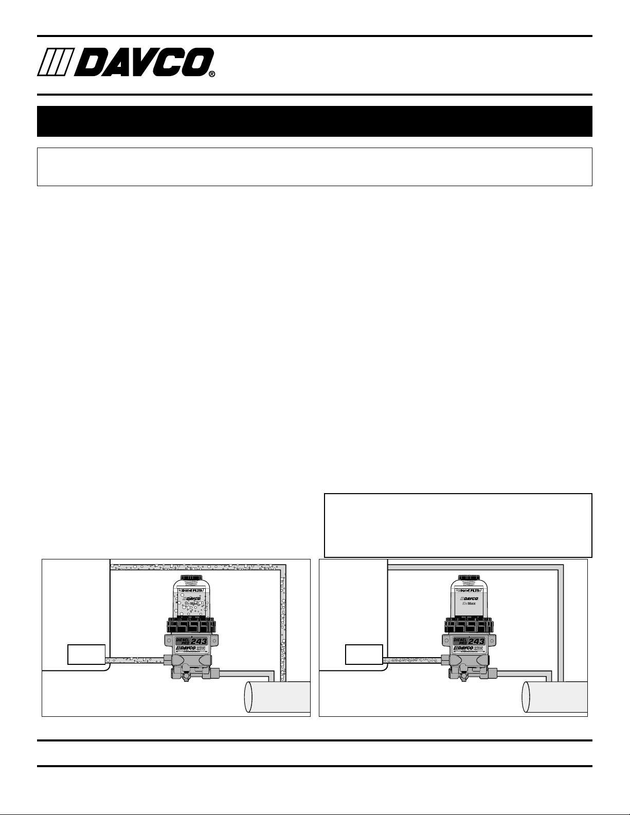
I. Air bubbles will be visible in the clear cover of the
DieselPro if the leak originates between the fuel tank and
the DieselPro. The following is a quick test to isolate the
air leak source.
A. Remove the DieselPro inlet hose.
1. Install a jumper hose from the DieselPro to the
fuel tank (through the fill cap) or to a container of
fuel.
2. Start the engine. If this eliminates the air bub-
bles, the air source is at the fuel tank fittings or
hose connections.
3. Tighten all fittings and connectors. Retest.
a. If air bubbles persist, the air source is on the
DieselPro side of the system:
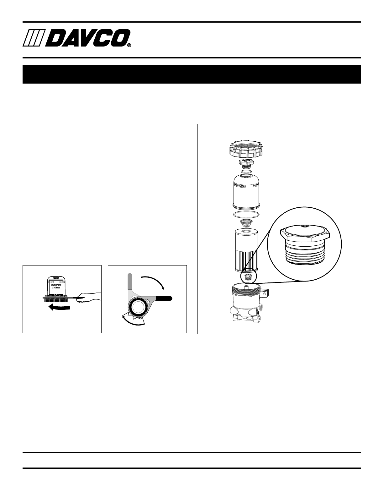
i. Tighten all fittings on the DieselPro.
ii. Loosen the collar until it spins freely.
Apply downward pressure on the top of
the cover and rotate the collar until con-
tact. Use a DAVCO wrench (if necessary)
to tighten the collar three additional ribs.
b. If the drain valve is suspected, install a plug
in place of the drain valve (for test purposes
only).
4. If air bubbles persist, test as follows:
a. Remove the DieselPro from the chassis.
Plug the fuel outlet port. Do not remove filter,
cover/collar, vent cap, drain valve and/or
check valve. If the DieselPro is equipped with
a pre-heater, do not remove the pre-heater.
b. Apply 15 PSI of air pressure at the fuel inlet.
Immerse the DieselPro in a tank of water and
look for air bubbles.
c. Correct the source of the air leak and retest.
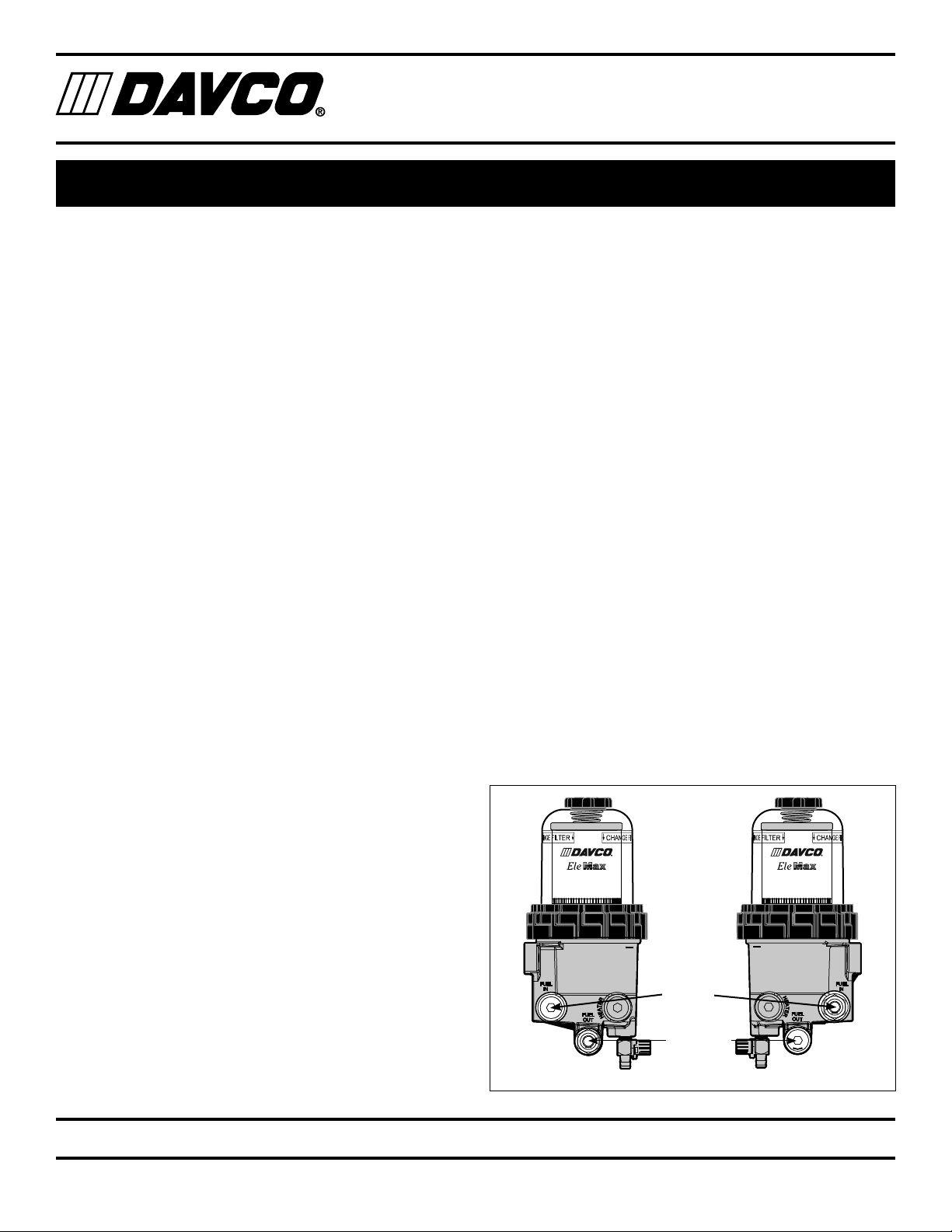
II. Bubbles Not Visible: If there are symptoms of sucking air
(indicated by engine loping⁄rough running performance⁄
power loss, etc.) and there are no bubbles in the clear
cover, the air leak is either at the DieselPro outlet tting,
vent cap o-ring, the lift pump inlet connection, or the fuel
hose⁄connections to the lift pump. Inspect and tighten
ttings as needed.
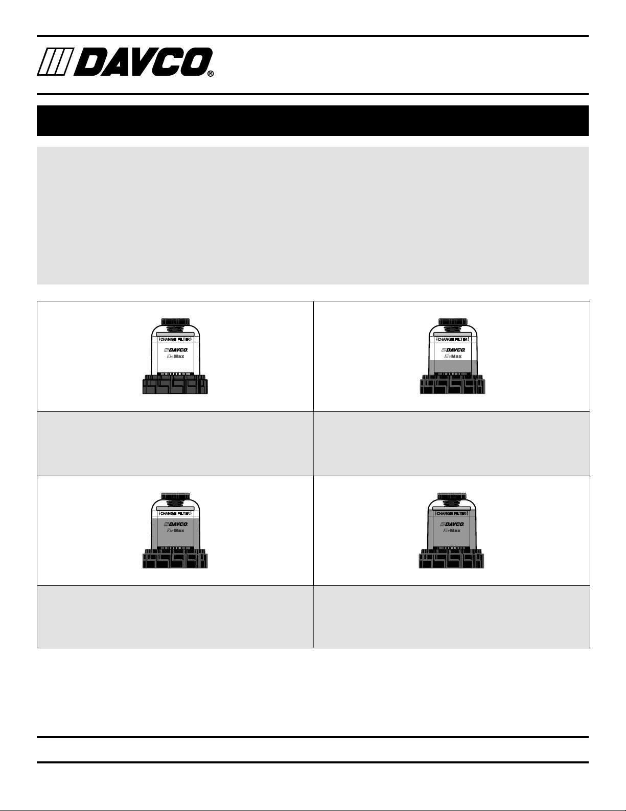
III. Excessive Restriction: If the fuel level is at the top of the
lter, replace the fuel lter. The DieselPro will not cause
excess system restriction if the fuel level is below the top
of the lter. The only exception is if the grommet is not
installed in the bottom of the lter element.
IV. Loss of Prime: When air is introduced into the fuel
system, (i.e. draining water from the DieselPro or when
replacing the fuel lter) a check valve is needed to keep
the fuel system primed from the DieselPro back to the
fuel tank. A check valve is standard with every DieselPro.
V. To test for proper check valve operation, put a drain pan
under the DieselPro, remove the fuel inlet hose and open
the vent cap. Fuel should not ow out of the DieselPro,
although slight seepage of fuel is normal.
If fuel flows out of the unit, follow the check valve testing
procedures on page 15.
DIESEL PRO®243 TECHNICAL MANUAL