Davco FUEL PRO 483 User manual

F1305 REV F
This manual applies to Fuel Pro 483 models with and without Coolant Heat.
Items marked with * indicate Coolant Heat features.
FOR UPDATED INFORMATION, VISIT WWW.DAVCO.COM
TABLE OF CONTENTS
Applications, Models, and Options.................. 1
How it Works................................... 1
“SEEING IS BELIEVING”®........................ 2
Dimensions and Specifications..................... 3
�Important Safety Precautions ................... 4
Mounting and Fuel Line Routing.................... 5
Coolant Hose Routing* ........................... 6
Upgrading Fuel Pro 483 to Coolant Heat* ............ 7
12VDC Electric Pre-heater Installation ............... 8
120VAC Electric Overnight Heater Installation ......... 9
Priming the Fuel System .......................... 9
Water in Fuel (WIF) Sensor Installation .............. 10
Preventive Maintenance ......................... 11
Filter Change Procedure ......................... 12
Visual Diagnostics.............................. 13
Diagnostic Procedures .......................... 14
Service Parts.................................. 16
Heaters & Water In Fuel (WIF) Sensors .............. 17
Warranty Policy ................................ 18
Parts Return Policy ............................. 19

FUEL PRO®483
TECHNICAL MANUAL
Technology, LLC
1
DAVCO Technology, LLC P. O. Box 487 Saline, MI 48176 800-328-2611 www.davco.com F1305 REV F
• Fuel from the tank enters the Fuel Processor body (suction side of the fuel system).
• Large contaminants and “free” water are separated from the fuel and remain in the body.
• Fuel rises into the clear cover.
• Contaminants and emulsified water are captured by the filter media.
• Fuel level rises to maintain a fuel path through the clean filter media and with lowest restriction.
• Clean, water-free fuel exits the Fuel Processor and flows to the engine fuel module.
Universal Applications
• Heavy duty diesel engines
• Supports flow rates up to 180
GPH
Options
• Electric Pre-heater Options
• 12 VDC pre-heater
• 120 VAC pre-heater
• Water-in-fuel sensor (WIF)
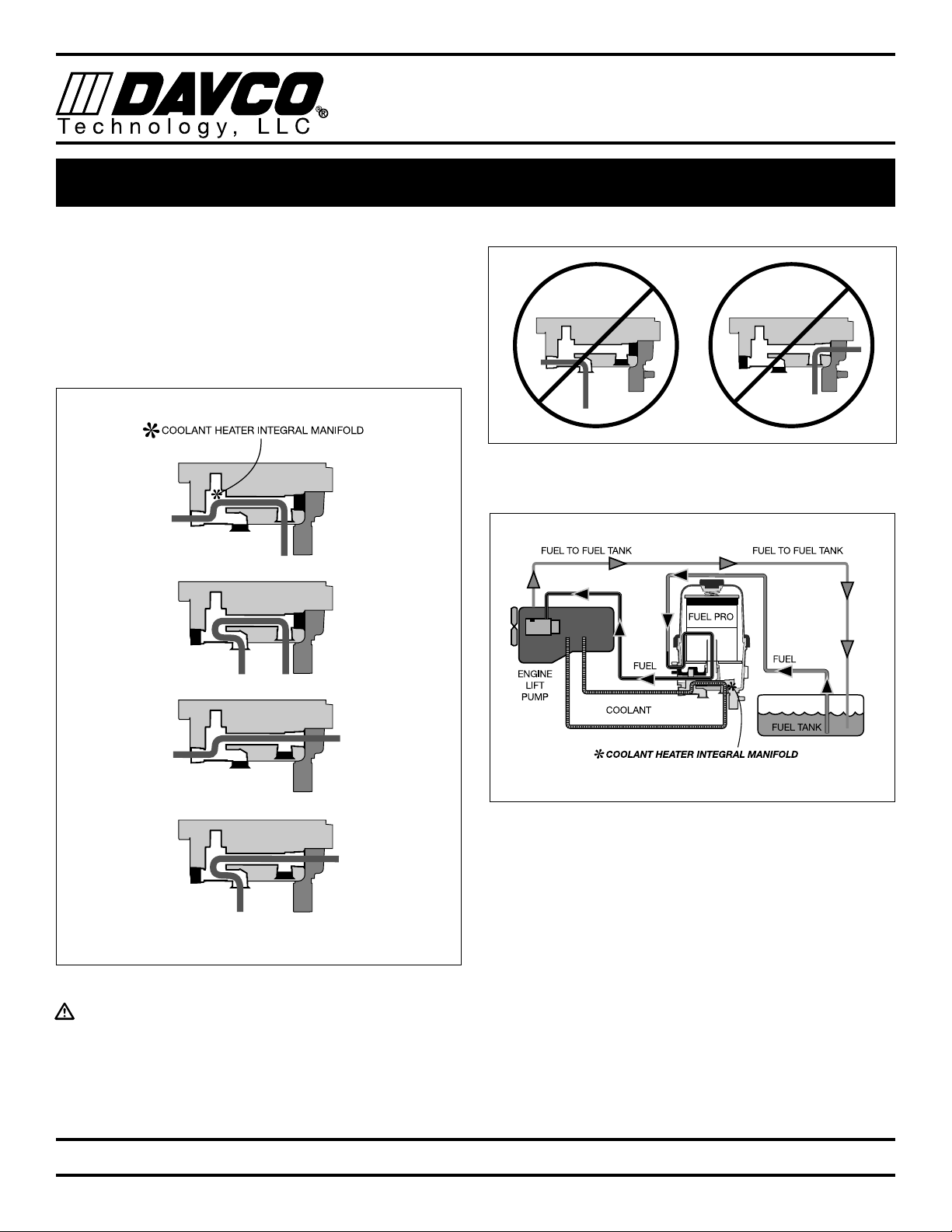
Fuel System Diagram showing Coolant Heat Connections
APPLICATIONS, MODELS, AND OPTIONS
HOW IT WORKS
FUEL PRO®483
TECHNICAL MANUAL
Technology, LLC
2
DAVCO Technology, LLC P. O. Box 487 Saline, MI 48176 800-328-2611 www.davco.com F1305 REV F
•
See when NOT to change the fuel filter.
•
See the condition of the fuel.
Seeing what collects on the filter media or what’s happening inside the clear cover can
help diagnose many fuel and mechanical conditions.
•
“Filter on Top”
configuration. Water and debris removed from the fuel falls to the lower chamber and stays away
from the filter media resulting in longer filter life.
•
Built in protection when priming the fuel filter.
Unfiltered fuel is kept on the “dirty” side of the filter media during
priming ensuring only clean fuel reaches the engine.
•
Patented media.
The “Best in Class” StrataPore™ media removes 98% of free and emulsified water over the life of
the filter. This far exceeds the performance of cellulose media.
“SEEING IS BELIEVING”®
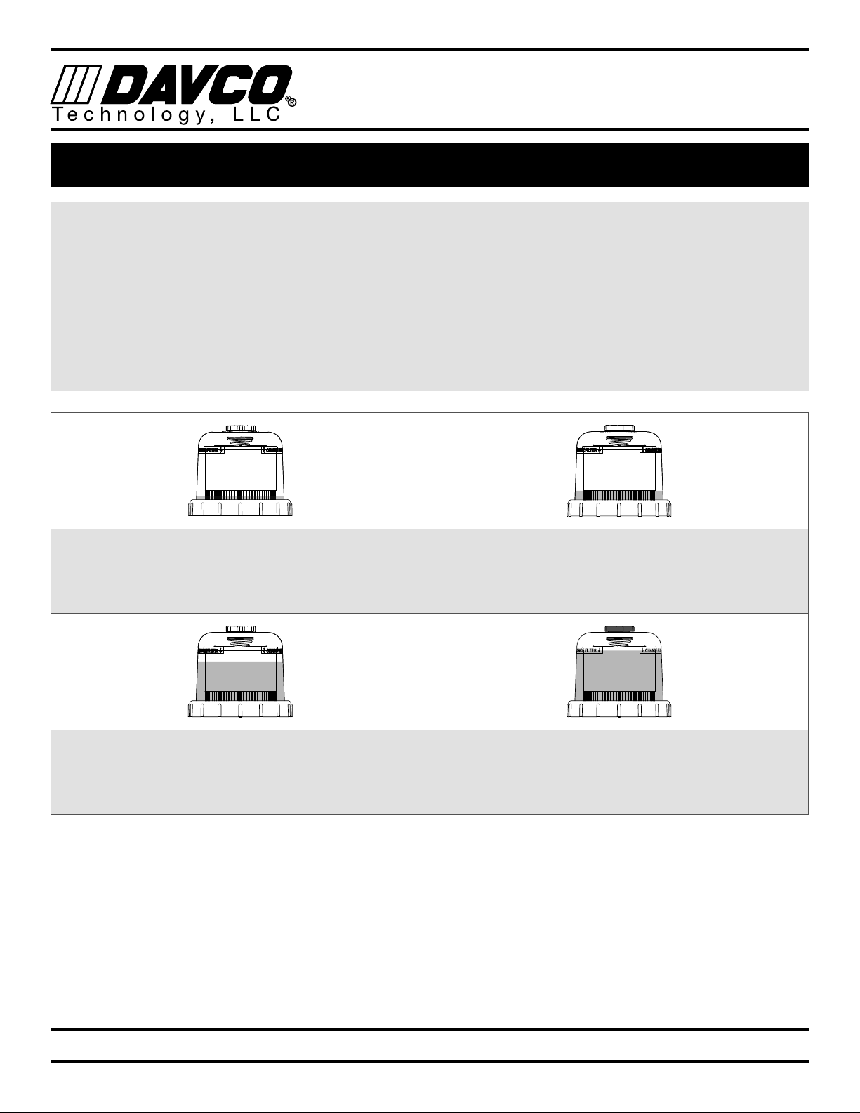
When new, the fuel level in the filter will be very low
with minimal restriction. As the filter is used, contami-
nants collect on the filter from the bottom up. Fuel rises
on the filter indicating remaining filter life.
Fuel level increases in clear cover. As contaminants
collect on the filter, the fuel rises to a non-contaminated
section of the filter, providing optimal filtration while main-
taining lowest restriction.
Fuel level at filter wrap level. Even though the fuel level
is now more than half of the filter element, the fuel is still
flowing through clean media at minimal restriction levels.
The filter still has significant life remaining.
The filter element is now completely covered by fuel.
At this point, all of the media’s surface area is utilized.
Restriction is increasing and the filter element should be
changed at the next scheduled maintenance interval.

FUEL PRO®483
TECHNICAL MANUAL
Technology, LLC
3
DAVCO Technology, LLC P. O. Box 487 Saline, MI 48176 800-328-2611 www.davco.com F1305 REV F
Specifications
Height Overall 14.28 in
Depth Overall 6.58 in
Width, Max. 8.35 in
Mount Bracket Centers 3.94 in
Weight, Dry 10.35 lbs
Fuel In Connection 1/2"-14 NPTF
Fuel Out Connection 1/2"-14 NPTF
Filter Service Clearance
Min 3.5 in (88.9 mm)
Max. Fuel Flow 180 gph
Electric Pre-heater 12VDC, 195 W, 18 A
120VAC, 75 W, .65 A
Filtration Performance at 100 GPH (EST.)
Micron Coarse Water
Removal (%)
Emulsified Water
Removal (%)
Dirt Holding Capacity
(grams)
7 mic 100 98.7 157
FRONT VIEW
RIGHT
LEFT
TOP VIEW BOTTOM VIEW
Note: These drawings reflect the left side Fuel In/Fuel Out
configuration. Fuel In is also available on the right side.
0.0
0.5
1.0
1.5
2.0
2.5
0 25 75 125 175 22550 100 150 200
7 micron
Differential Pressure (in-Hg)
Flow (gph)
Restriction vs. flow
DIMENSIONS AND SPECIFICATIONS

FUEL PRO®483
TECHNICAL MANUAL
Technology, LLC
4
DAVCO Technology, LLC P. O. Box 487 Saline, MI 48176 800-328-2611 www.davco.com F1305 REV F
IMPORTANT SAFETY PRECAUTIONS
General Safety Precautions
• Read all instructions before use to avoid injury.
• To avoid serious injury or death, follow the safety information in this document.
• Keep this manual. If you need to replace the manual, call customer service at 800-328-2611
or visit www.davco.com/documents for a replacement.
• Read all product safety labels.
• Refer to appropriate regulations for environmental and workplace safety rules.
WARNING: To prevent personal injury
• Scalding hazard: When diesel fuel is circulated through an operating engine, it can become very hot. Do not al-
low fuel to come in contact with eyes or unprotected skin. Allow the engine and fuel to cool to ambient tempera-
ture before replacing the fuel filter or performing service operations which could result in spillage of fuel from the
fuel system.
• Fire Prevention: Heated fuel can form combustible vapor mixtures in the area around the fuel source. To elimi-
nate the potential for fire, keep open flames, sparks or other potential ignition sources away from the work area.
Do not smoke during filter replacement or service operations.
• Inhalation Precaution: Always perform engine or vehicle fuel system maintenance in a well ventilated area that is
kept free of bystanders.
• The ignition key must be in the off position, unless otherwise directed. To avoid unintentional engine startup, use
a lockout key and/or signage to alert personnel that work is being performed.
Government Regulations
• Engine fluids (oil, fuel, and coolant) may be a hazard to human health and the environment. Handle all fluids and
other contaminated materials (such as filters and rags) in accordance with applicable regulations. Recycle or dis-
pose of engine fluids, filters, and other contaminated materials according to applicable regulations.

FUEL PRO®483
TECHNICAL MANUAL
Technology, LLC
5
DAVCO Technology, LLC P. O. Box 487 Saline, MI 48176 800-328-2611 www.davco.com F1305 REV F
Installation Location
The Fuel Pro must be installed between the fuel tank and
the fuel transfer pump. In some cases, the Fuel Pro can be
used as the only fuel filter in the system. This is generally
dependent on the engine model year. Consult the engine
manufacturer for their recommendation.
Mounting the Fuel Pro
• Do not install the Fuel Pro directly on the engine.
• Mount vertically with the cover and element pointing
up.
• Make sure there is enough top and side clearance for
the cover to be conveniently removed for filter replace-
ment.
• The Fuel Pro MUST be installed so that the filter ele-
ment is above the "FULL" level of the fuel tank.
�The ignition key must be in the off position, unless
otherwise directed. To avoid unintentional engine
startup, use a lockout key and/or signage to alert
personnel that work is being performed. Chock the
wheels.
1. With the engine shut down and at ambient temperature,
close the fuel shutoff valve (if equipped) and place a
suitable container under the fuel filters.
2. Remove the primary fuel filter element assembly, sedi-
menter, and/or water separator. Drain the used element
and dispose of it in an environmentally responsible
manner, according to state and/or federal (EPA) recom-
mendations.
Fuel Line Routing
To minimize fuel system restriction, observe the follow-
ing guidelines when plumbing the fuel system:
• Keep the fuel line routing as smooth as possible with
no low-hanging loops which can trap water.
• Use 90° elbows only when necessary.
• If the fuel hoses are cut to length on the job, be sure
that the inner liner of the fuel hose is not cut by the fit-
ting, which can cause check valve performance issues.
Make sure hoses are clean and free of debris before
installing.
• To avoid damaging the aluminum Fuel Pro body, do not
overtighten fuel lines or fuel linåe fittings.
3. Route the fuel supply line from the pick up on the fuel
tank to the Fuel Pro inlet (labeled “FUEL IN” on figure
below, not labeled on housing).
4. Route the fuel outlet line from the Fuel Pro outlet (la-
beled “FUEL OUT”) to the inlet of the fuel pump.
Note: The drawing below reflects the left side Fuel In/Fuel
Out configuration. Fuel In is also available on the right side.
FUEL IN
FUEL OUT
MOUNTING AND FUEL LINE ROUTING
FUEL PRO®483
TECHNICAL MANUAL
Technology, LLC
6
DAVCO Technology, LLC P. O. Box 487 Saline, MI 48176 800-328-2611 www.davco.com F1305 REV F
COOLANT HOSE ROUTING*
Coolant flow is not direction sensitive through the Fuel Pro
483 Coolant Heater Integral Manifold.
1. Connect a high pressure hose on either side (or bottom)
of the Fuel Pro 483 and a low pressure hose on the op-
posite side or bottom (Figure 1).
Note: Coolant hoses must be connected so the coolant
flows completely though the Coolant Heater Integral Mani-
fold*
Figure 1
COOLANT LINES MUST BE
PARALLEL, NOT IN SERIES.
Do not connect coolant hose as shown in Figure 2.
Figure 2
Note: “Y” or “T” connectors can be used in the cab heater
hoses if an engine port is unavailable.
2. Start the engine and check for leaks in the coolant
hoses.
Note: Coolant flow is not directionally sensitive.

FUEL PRO®483
TECHNICAL MANUAL
Technology, LLC
7
DAVCO Technology, LLC P. O. Box 487 Saline, MI 48176 800-328-2611 www.davco.com F1305 REV F
Note: Steps 1 thru 4 can be skipped if the Fuel Pro 483
coolant heat ports are easily accessible.
1. Remove the vent cap and drain the Fuel Pro complete-
ly.
2. Disconnect the fuel inlet and outlet hoses.
3. Disconnect all electrical components (if equipped).
4. Remove the Fuel Pro from the truck and mount in a vise
so the Coolant Heater Integral Manifold area is acces-
sible.
5. Remove the Thermovalve plug using a 1¼" socket or
wrench and discard.
Note: To identify if your Fuel Pro 483 has a thermovalve
installed, the thermovalve plug will be gold in color.
6. Install the Thermovalve assembly with the brass sens-
ing probe first. Be careful to guide the Thermovalve into
the port straight without damaging the o-rings.
7. Torque to 30-55 ft-lbs.
8. Remove a ½" NPT steel plug from each side/bottom of
the Coolant Heater Integral Manifold.
�CAUTION: A coolant shutoff valve is required
for summer operation for most engines,
until the DAVCO Thermovalve is available.
A shutoff valve can be installed in either of
the coolant ports in the Fuel Pro 483 or the
coolant hoses going to these ports.
9. The ports are available on the bottom and side of the
Coolant Heater Integral Manifold for ideal fitting clear-
ance per application. Only one port per side can be
used to ensure ample coolant flow across the body.
Coolant flow is not direction sensitive.
Note: Do not connect as shown below.
10. Select suitable ½" NPT to 5/8" barb fittings – straights,
45°s or 90°s can be used, based upon application
requirements.
11. Apply liquid thread sealant to the threads of the fittings.
Note: Do not apply sealant to the first two threads of the fit-
ting. This is to prevent excess sealant from getting into the
coolant cavity of the Fuel Pro.
12. Install the fittings and torque to 15-30 ft-lbs. Position
the fittings as needed.
13. Install the Fuel Pro 483 and torque the mounting hard-
ware to OEM specifications.
14. Connect the electrical components.
15. Connect the fuel inlet and outlet hoses.
16. Connect a hose from the high pressure side of the
engine coolant system to the Fuel Pro Coolant Heater
Integral Manifold.
�Coolant lines must be parallel, not in series.
17. Connect a hose from the Coolant Heater Integral Mani-
fold to a low pressure side in the coolant system.
Note: “Y” or “T” connectors can be used in the cab heater
hoses if no engine ports are available.
18. Prime the unit by filling the clear cover with clean diesel
fuel until it reaches the top of the filter.
19. Install the vent cap. Tighten it by hand until it clicks.
20. Start the engine and run for one minute. Slowly open
the vent cap and allow the fuel to drop to about one
inch above the collar.
21. Close the vent cap. Tighten it by hand until it clicks.
Note: It is normal for the fuel level to vary after the initial
start-up and during engine operation. Filter performance is
not affected.
UPGRADING FUEL PRO 483 TO COOLANT HEAT*

FUEL PRO®483
TECHNICAL MANUAL
Technology, LLC
8
DAVCO Technology, LLC P. O. Box 487 Saline, MI 48176 800-328-2611 www.davco.com F1305 REV F
85
30/51
87
86
12/24 VDC
OPTIONAL
RELAY
+ -
Heater
Pre-heater Fuse
Harness
Connector
Ignition
Circuit
Fuse
87A
87
86
85
30/51
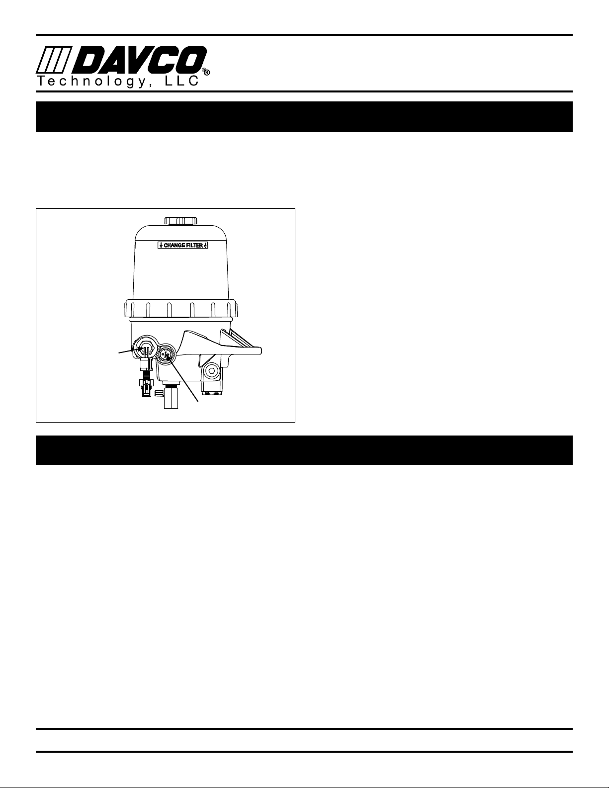
The Fuel Pro 483 12VDC or 120VAC electric pre-heater is
installed in the side of the fuel processor.
The drawing below reflects the left side Fuel In/Fuel Out
configuration. Fuel In is also available on the right side.
120VAC Heater Port
12VDC Heater Port
1. Drain all the fuel from the Fuel Pro. The fuel can be
reused after the pre-heater is installed. If the fuel is not
reused, dispose of it in an environmentally safe way.
2. Remove the pipe plug in the Fuel Pro base plate.
3. Apply liquid thread sealant to the pre-heater threads
and install into the Fuel Pro base. Tighten to 15-30 ft-
lbs.
4. Connect the chassis harness to the Fuel Pro harness.
5. Connect the power lead to the fused accessory side of
the ignition switch. The fuse rating depends on the pre-
heater installed. Recommended fuse is not included
with the FuelPro kit.
6. Use a relay if the ignition circuit will not handle a mini-
mum required current for the selected heater.
The following is a list of approved fuse ratings.
• 12 VDC System:
- 15 amp Fuse for a 150W heater
- 20 amp Fuse for a 155W PTC heater
- 25 amp Fuse for a 195W PTC heater
• 24 VDC System:
- 10 amp Fuse for a 150W heater
- 15 amp Fuse for a 195W PTC heater.
12VDC ELECTRIC PRE-HEATER INSTALLATION
Pre-heater Wiring with Relay PTC pre-heaters require a 25 AMP fuse. If the keyed circuit will not handle a
minimum of 25 amps, use a relay.
Battery
Fuse
+
–
Pre-heater Circuit with Fuse
Pre-heater
Pre-heater Wiring without Relay
*24VDC pre-heaters require a 15 A fuse.
FUEL PRO®483
TECHNICAL MANUAL
Technology, LLC
9
DAVCO Technology, LLC P. O. Box 487 Saline, MI 48176 800-328-2611 www.davco.com F1305 REV F
1. Check to make sure the drain valve at the base of the
Fuel Pro is closed. Remove the vent cap.
2. Fill the clear cover with clean diesel fuel until it reaches
the top of the filter.
3. Install the vent cap. Tighten it by hand until it clicks.
4. Start the engine and run for one minute. Open the vent
cap and allow the fuel to drop to about one inch above
the collar. Close the vent cap. Tighten it by hand until it
clicks.
5. Check for any possible leaks. It is normal for the fuel
level to vary after the initial start-up and during engine
operation. Filter performance is not affected.
The Fuel Pro 483 12VDC electric preheater or 120VAC
electric overnight heater is installed in the side of the fuel
processor.
Note: The drawing below reflects the left side Fuel In/Fuel
Out configuration. Fuel In is also available on the right side.
120VAC Heater Port
12VDC Heater Port
1. Drain all the fuel from the Fuel Pro. The fuel can be
reused after the heater is installed. If the fuel is not
reused, dispose of it in an environmentally safe way.
2. Remove the pipe plug from the Fuel Pro body.
3. Apply liquid thread sealant to the pre-heater threads
and install the pre-heater into the Fuel Pro body.
Tighten to 15-30 ft-lbs.
4. Connect the wire harness to the heater and route to a
location where it can be plugged into a 120VAC outlet.
5. Check to make sure the drain valve at the base of the
Fuel Pro is closed.
6. Fill the clear cover with clean diesel fuel until it reaches
the top of the filter.
7. Install the vent cap. Tighten it by hand until it clicks.
8. Start the engine and run for one minute. Open the vent
cap and allow the fuel to drop to about one inch above
the collar. Close the vent cap. Tighten it by hand until
it clicks.
9. Check for any possible leaks. It is normal for the fuel
level to vary after the initial start-up and during engine
operation. Filter performance is not affected.
120VAC ELECTRIC OVERNIGHT HEATER INSTALLATION
PRIMING THE FUEL SYSTEM
FUEL PRO®483
TECHNICAL MANUAL
Technology, LLC
10
DAVCO Technology, LLC P. O. Box 487 Saline, MI 48176 800-328-2611 www.davco.com F1305 REV F
1. Drain all the fuel from the Fuel Pro. The fuel can be re-
used after the WIF is installed. If the fuel is not reused,
dispose of it in an environmentally safe way.
2. Remove the plug in the Fuel Pro body.
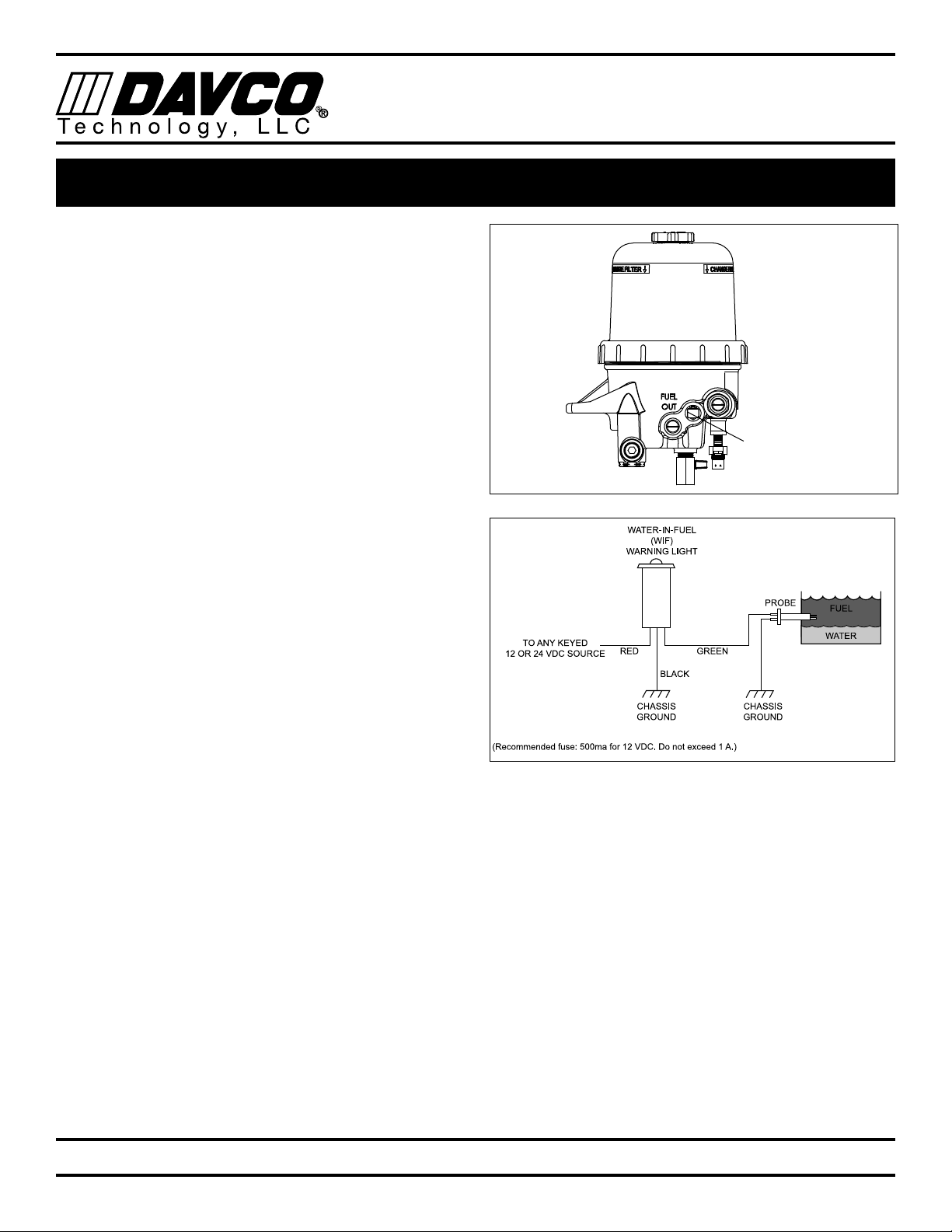
3. Install the WIF Probe into the left side of the Fuel Pro.
Torque to 20-24 in-lbs.
4. Install the WIF wiring harness (P/N 102600) on WIF
Probe. The harness has the following connections:
black ground lead with a 3/8" diameter ring terminal
and a green WIF wire.
5. Drill ½" hole in the instrument or control panel where
the WIF indicator light is to be located.
6. Connect the black ground wire from the WIF indicator
light to a ground source. Attach additional black wire as
needed.
7. Install the WIF indicator light by pressing firmly into the
drilled hole.
8. Connect the black ground lead with a 3/8" diameter
loop end on the WIF wiring harness to the ground
source near the Fuel Pro (if applicable).
9. Connect the green signal wire on WIF wiring harness to
green signal wire on WIF indicator light. Use additional
green wire as needed.
10. Locate 12VDC key controlled on power source. Install a
red wire from the power source to the red wire on WIF
indicator light. Add a 1 amp in-line fuse (not included).
11. Use appropriate connectors to attach the wires. To test
the WIF indicator light, pour water into the body of the
Fuel Pro until it covers the WIF probe. The WIF indica-
tor light should illuminate. Drain the water.
12. Check to make sure the drain valve at the base of the
Fuel Pro is closed.
13. Fill the clear cover with clean diesel fuel until it reaches
the top of the filter.
14. Install the vent cap. Tighten it by hand until it clicks.
15. Start the engine and run for one minute. Open the vent
cap and allow the fuel to drop to about one inch above
the collar. Close the vent cap. Tighten it by hand until
it clicks.
16. Check for any possible leaks. It is normal for the fuel
level to vary after the initial start-up and during engine
operation. Filter performance is not affected.
WIF Location
WATER IN FUEL (WIF) SENSOR INSTALLATION

FUEL PRO®483
TECHNICAL MANUAL
Technology, LLC
11
DAVCO Technology, LLC P. O. Box 487 Saline, MI 48176 800-328-2611 www.davco.com F1305 REV F
Weekly – Drain Water
• Turn off the engine and open the vent cap.
• Place a drain pan under the drain valve at the
base of the Fuel Pro and open the valve.
• Water will flow into the container. When fuel be-
gins to flow out the drain, close the drain valve.
Drain the least amount of fuel as possible.
• Close the vent cap. Tighten it by hand until it
clicks.
• Start the engine. Raise the RPM for one minute
to purge the air from the system.
Every Filter Change
• Change the cover and vent cap o-rings (included
with the service filter kit).
Every 12 Months
• Check all electrical connections for corrosion.
Check all fuel fittings for leaks.
• Extreme winter or salt corrosion environments may
require lubrication of the collar threads with
anti-seize lubricant every 180 days.
PREVENTIVE MAINTENANCE
FUEL PRO®483
TECHNICAL MANUAL
Technology, LLC
12
DAVCO Technology, LLC P. O. Box 487 Saline, MI 48176 800-328-2611 www.davco.com F1305 REV F
FILTER CHANGE PROCEDURE
1. Remove the vent cap and open the drain valve to drain
the fuel below the collar level.
2. Remove the collar (using a DAVCO wrench) then re-
move the clear cover.
3. Remove the filter, cover and vent cap seals. Dispose of
properly.
4. Using a clean shop rag, clean the cover, the collar and
threads on the Fuel Pro body.
5. Install a new filter, cover seal and vent cap seal.
6. To tighten the collar with the wrench, simultaneously
apply downward pressure to the top of the clear cover
until it is seated on the body of the Fuel Pro and hand
tighten the collar until it no longer spins freely. Torque
the cover assembly by rotating the collar clockwise two
additional ribs using the collar wrench (~18 ft-lbs).
7. Prime the unit by filling the clear cover with clean diesel
fuel until it reaches the top of the filter.
8. Install the vent cap and hand tighten until it clicks. Start
the engine and run for one minute. Slowly open the
vent cap and allow the fuel to drop to about one inch
above the collar.
9. Close the vent cap. Tighten the vent cap by hand until
it clicks. It is normal for the fuel level to vary after the
initial start-up and during engine operation. Filter per-
formance is not affected.
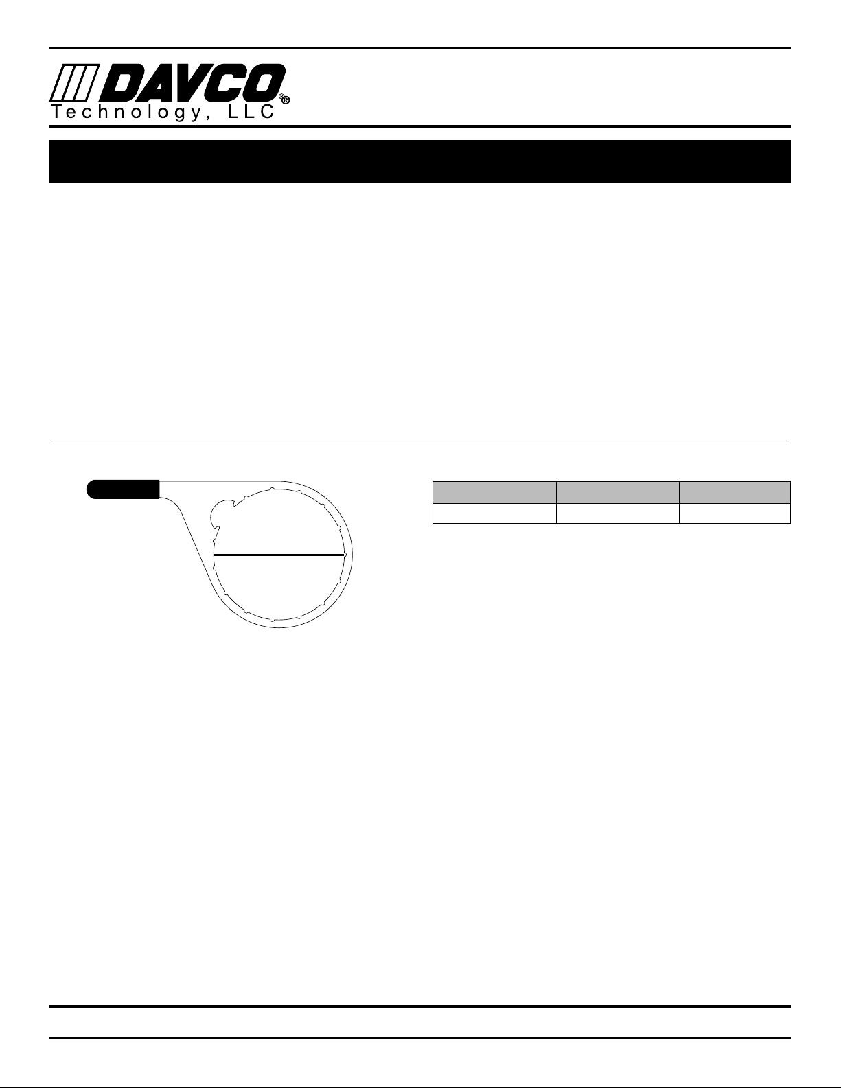
Collar Wrench
P/N 482017
8 in.
Tightening the collar with the wrench:
Simultaneously apply downward pressure to the top of the
clear cover until it is seated on the body of the Fuel Proand
hand tighten the collar until it no longer spins freely. Torque
the cover assembly by rotating the collar clockwise two ad-
ditional ribs using the collar wrench (~18 ft-lbs).
Note: The DAVCO Fuel Pro collar is designed to be re-
moved with a DAVCO wrench. Collars damaged as a result
of not using the DAVCO wrench will not be covered under
warranty.
Recommended Filters
Brand P/N Micron
Fleetguard FS19915 7

FUEL PRO®483
TECHNICAL MANUAL
Technology, LLC
13
DAVCO Technology, LLC P. O. Box 487 Saline, MI 48176 800-328-2611 www.davco.com F1305 REV F
VISUAL DIAGNOSTICS
AIR BUBBLES VAPOR BUBBLES
Air Bubbles
Air bubbles are caused by any air leak on the vacuum (suc-
tion) side of the fuel system from the fuel tank pick-up to,
and including, the lift pump.
If there is an air leak in the fuel system, air bubbles will be
present in the clear cover of the Fuel Pro follow Diagnostic
Procedures (page 14) for air leak diagnostics. If there are
no bubbles present in the Fuel Pro cover and the engine
continues to run rough, lopes or has a loss of power, there
may be an air leak between the Fuel Pro outlet port and lift
pump inlet. This type of air bubble can be seen if a sight
tube is installed at the lift pump inlet. Air bubbles may also
be visible in the fuel return (spill) hose out of the fuel gallery.
These leaks are easily eliminated by checking and torquing
the fuel fittings in the area of the leak.
NOTE 1: A quick procedure to determine if the air leak is
between the fuel tank and the Fuel Pro is to remove the
Fuel Pro inlet hose and route a new hose from the Fuel
Pro inlet into a container of fuel or the fuel tank fill cap
opening. Start the engine and check for bubbles.
If there are no air leak symptoms, but bubbles are present
in a sight tube at the fuel lift pump inlet, they are most likely
vapor bubbles.
Vapor Bubbles
All diesel fuel has some level of entrained air caused by the
natural splashing that occurs in the fuel tank during normal
vehicle or equipment operation. Vapor bubbles develop
in the Fuel Pro because the pressure inside the Fuel Prois
lower than the atmospheric pressure in the fuel tank. Vapor
bubbles can vary from champagne size up to ¼" in diam-
eter. They may increase in size or volume as engine rpm
increases. The lower pressure draws the entrained air/vapor
out of the fuel and these bubbles will be visible as the fuel
exits the Fuel Pro.
As the fuel enters the lift pump, it is pressurized and the
bubbles are compressed back into the fuel. There will be no
bubbles on the fuel return side of the system. These vapor
bubbles will not affect the performance of the engine.
NOTE 2: An easy way to determine the difference between
vapor and air bubbles is by temporarily removing the filter
element from the Fuel Pro. Fill the cover with clean diesel
fuel, replace the vent cap. Tighten the vent cap by hand
until it clicks. Re-run the outlet fitting sight glass test. If
there are no bubbles present in the sight glass then they
were vapor. If bubbles are still present then they are air. If air
bubbles still exist, re-run the test in NOTE 1 to eliminate the
chassis plumbing as a variable.
There is no troubleshooting or repair procedure re-
quired for vapor bubbles. Vapor bubbles do not cause
performance issues and will not be present after the lift
pump.
There are two kinds of bubbles that may be visible at the fuel pump inlet of a diesel fuel system. The bubbles
can be characterized as either air bubbles or vapor bubbles.

FUEL PRO®483
TECHNICAL MANUAL
Technology, LLC
14
DAVCO Technology, LLC P. O. Box 487 Saline, MI 48176 800-328-2611 www.davco.com F1305 REV F
Every Fuel Pro 483 is factory tested for leaks and is marked
with a traceable number to show that it has passed produc-
tion testing.
Most field issues associated with leaks are related to loose
fittings. These leaks are easily eliminated by checking and
torquing the fuel fittings in the area of the leak. Some fit-
tings may also require the application of liquid Teflon sealer.
NOTE: All suction side fuel filters experience bubbles. It is
normal to see champagne size bubbles in the Fuel Pro 483
at the fuel outlet or at the lift pump.
IN ORDER TO RETURN A FUEL PRO 483 FOR EVALU-
ATION, THE FOLLOWING PROCEDURES/TESTS NEED
TO BE COMPLETED BEFORE REQUESTING A DAVCO
RGA (RETURN GOODS AUTHORIZATION).
I. Air Leak: Air bubbles will be visible in the clear cover
of the Fuel Pro 483 if the leak originates from the fuel
tank up to the fuel filter. The following is a quick test to
isolate the air leak source.
A. Bubbles Visible: Remove the Fuel Pro 483 inlet
hose.
i. Install a jumper hose from the Fuel Pro 483
to the fuel tank (through the fill cap) or to a
container of fuel.
ii. Start the engine. If this eliminates the air
bubbles, the air source is at the fuel tank
fittings or hose connections.
1. Tighten all fittings and connectors
2. Retest
iii. If air bubbles persist, the air source is on the
Fuel Pro 483 side of the system:
1. Tighten all fittings on the Fuel Pro 483.
2. Hand tighten the top collar.
3. If the drain valve is suspected, install a
plug in place of the drain valve (for test
purposes only).
iv. If air bubbles continue to persist, test as
follows:
1. Remove the Fuel Pro 483 from the
chassis.
2. Plug fuel outlet port. Do not remove
filter, cover/collar, vent cap, drain valve
and/or check valve. If the Fuel Pro 483
is equipped with a preheater, do not
remove the preheater.
3. Apply 15 PSI of air pressure at the fuel
inlet. Immerse the Fuel Pro 483 in a
tank of water and look for air bubbles.
4. Correct the source of the air leak and
retest.
B. Bubbles Not Visible: If there are symptoms of
sucking air (indicated by engine loping/rough run-
ning performance/power loss, etc.) and there are
no bubbles in the clear cover, the air leak is either
at the Fuel Pro 483 outlet fitting, vent cap o-ring,
the lift pump inlet connection, or the fuel hose/
connections to the lift pump. Inspect and tighten
fittings as needed.
II. Excessive Restriction: If the fuel level is at the top of
the filter, replace the fuel filter. The Fuel Pro 483 will not
cause excess system restriction if the fuel level is below
the top of the filter. The only exception is if the grom-
met is not installed in the bottom of the filter element.
III. Loss of Prime: When air is introduced into the fuel
system, (i.e. draining water from the Fuel Pro 483 or
when replacing the fuel filter) a check valve is needed
to keep the fuel system primed from the Fuel Pro 483
back to the fuel tank. A check valve is standard with all
Fuel Pro 483s.
C. To test for proper check valve operation, remove
the fuel inlet hose and open the vent cap. Fuel
should not flow out of the Fuel Pro 483, although a
slight seepage of fuel is normal.
D. If fuel drains back to the fuel tank, remove the
check valve assembly at the fuel inlet fitting. Disas-
semble the check valve assembly. Clean and in-
spect. Replace the assembly if any cuts, grooves or
nicks are evident in the ball or body seat. Reinstall
the check valve assembly.
DIAGNOSTIC PROCEDURES

FUEL PRO®483
TECHNICAL MANUAL
Technology, LLC
15
DAVCO Technology, LLC P. O. Box 487 Saline, MI 48176 800-328-2611 www.davco.com F1305 REV F
DIAGNOSTIC PROCEDURES - HEATER TESTING
There are various configurations of electric pre-heaters and
thermoswitches available for the Fuel Pro. These include
12VDC pre-heaters, 24VDC pre-heaters, 120VAC pre-heat-
ers/thermoswitches, and combination pre-heater thermo-
switches. The voltage and wattage ratings are stamped
either on the sheath or the hex of each component for
identification.
Equipment Needed
• A precision low resistance ohm meter capable of mea-
suring 1/10th ohm or less.
• Current flow meter (clamp-on type for DC current).
• Ice, dry-ice, CO2 or some means of chilling the thermo-
switch.
• A flameless source of heat. (ie: infrared heat lamp, etc.)
Note: A Vortex tube is a good tool to heat and cool for
testing.
�DO NOT USE a test light that has a wire probe
for any of these tests. If the wiring insulation is
punctured, moisture and road salt can penetrate
into the wires creating a corrosion issue and
potential failure.
Draining the Fuel Pro
1. Shut off the engine and set the parking brake.
2. Attach a length of hose to the drain valve and place a
receptacle under the Fuel Pro.
3. Loosen the vent cap on top of the clear housing. Open
the drain valve and drain the fuel into the receptacle.
4. When the fuel is drained, close the drain valve.
Pre-heater Operation Test
1. Disconnect the pre-heater from the harness.
2. Connect the ohm meter leads to the pins of the pre-
heater. For heaters with one pin, connect to the pin
and the bushing. Use the following to determine
whether the pre-heater resistance value is in the ac-
ceptable range.
Pre-heater Watts Resistance Range (ohms)
12VDC (two pin) 250 W 0.6 to 0.8 @ 77°F (25°C)
12VDC (single pin) 250 W 0.6 to 0.8 @ 77°F (25°C)
12VDC (single pin) 150 W 0.8 to 1.1 @ 77°F (25°C)
12VDC (two pin) 150 W 0.8 to 1.1 @ 77°F (25°C)
24VDC (two pin) 250 W 2 to 2.5 @ 77°F (25°C)
24VDC (single pin) 250 W 1.8 to 2.3 @ 77°F (25°C)
24VDC (single pin) 150 W 3.6 to 4.1 @ 77°F (25°C)
24VDC (two pin) 150 W 3.6 to 4.1 @ 77°F (25°C)
120VAC 75 W 173 to 203 @ 77°F (25°C)
120VAC 37 W 369 to 411 @ 77°F (25°C)
Combination Pre-heater Thermoswitch Performance
Test
1. Disconnect the harness from the heater/thermoswitch
combination unit.
2. Using one of the cooling methods listed under "Equip-
ment Needed", reduce the temperature of the thermo-
switch to below 40° F.
3. Connect the ohm meter leads to the pre-heater pins.
Use Table 1 to determine whether the pre-heater resis-
tance value is in the acceptable range.
4. Using one of the pre-heating devices listed under
“Equipment Needed”, raise the temperature of the
combination pre-heater to 70°F. The ohm meter should
read “open circuit” for the combination units.
12 VDC PTC/24VDC Performance Test
1. Disconnect the harness from the heater.
2. Connect the ohm meter leads to the pins of the heater.
Use the following to determine whether the pre-heater
resistance value is in the acceptable range.
PTC Heater Watts Resistance Range (ohms)
12VDC (PTC) 195 W 0.4 to 0.6 @ 77°F (25°C)
24VDC (PTC) 195 W 2.0-3.0 @ 77°F (25°C)
12VDC (PTC) 155W 0.95 to 1.2 @ 77°F (25°C)

FUEL PRO®483
TECHNICAL MANUAL
Technology, LLC
16
DAVCO Technology, LLC P. O. Box 487 Saline, MI 48176 800-328-2611 www.davco.com F1305 REV F
SERVICE PARTS
Drain valve
WIF
Collar
Cover Assembly
(Includes Cover and
O-ring.)
Spring
O-ring
service kit Vent cap
service kit
Filter element
12VDC
Pre-heater
120VAC
Overnight heater
Check valve
assembly.
See detail below.
Note: The drawing above reflects the left side Fuel In/Fuel Out
configuration. Fuel In is also available on the right side.
Service Parts
Description P/N
Check Valve Assembly, with body,
1/2"-14NPTF
103071DAV
Collar 482003SDAV
Cover Assembly (Cover and O-ring) 483047SDAV
Drain Valve 102008
Spring 380056
Filter: Refer to Filter Matrix F3105
(www.davco.com/parts.html)
Check Valve Service Kit: 101132
Check Valve Assembly (with body): 103071DAV
Service Kits
Description Included in Kit Part Number
Check valve
service kit
Ball, spring and
retainer
101132
ESOC
service kit
(not shown)
Fitting and dust
cover
102844
O-ring
service kit
Vent cap and Cover
O-rings
482022
Vent cap
service kit
Vent cap and
Vent cap O-ring
240023DAV
Coolant Heat Service Parts
(Applies to Fuel Pro 483 with coolant heat)
Thermo-valve Coolant Port Plug Thermo-valve Port
Cap
483029DAV 103249 101999DAV
Service Tool
Metal Collar
Wrench
482017
FUEL PRO®483
TECHNICAL MANUAL
Technology, LLC
17
DAVCO Technology, LLC P. O. Box 487 Saline, MI 48176 800-328-2611 www.davco.com F1305 REV F
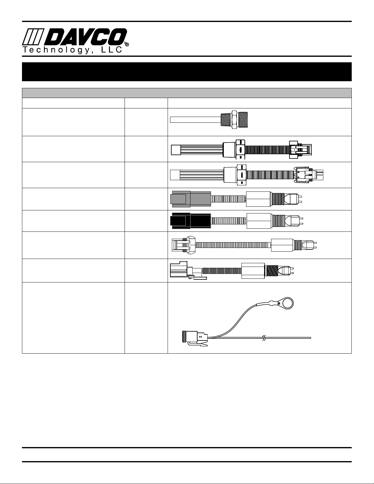
HEATERS & WATER IN FUEL (WIF) SENSORS
WIF AND PRE-HEATER PART NUMBERS
Description Part Number
120VAC Overnight heater
75W, 120V
102145
12VDC Pre-heater (Metri-Pack)
195W, 12V,
103528
12VDC Pre-heater (Weather-Pack)
195W, 12V
103529
WIF (Deutsch Connector)
grey connector
102512
WIF (Deutsch Connector)
black connector
102521
WIF (Metri-Pack Connector) 102770
WIF (Navistar)(Amp Connector) 102871
WIF Wiring Harness 102600 To be used with WIF 102512, 102521

FUEL PRO®483
TECHNICAL MANUAL
Technology, LLC
18
DAVCO Technology, LLC P. O. Box 487 Saline, MI 48176 800-328-2611 www.davco.com F1305 REV F
Product Warranty
Diesel Pro®243, Diesel Pro®245, Fuel Pro®382, Fuel Pro®482, Fuel Pro®483, Fuel Pro®485,
Fuel Pro®486, Fuel Pro®487, Industrial Pro®, Shop Pro®, Pro-Chek®, Sea Pro®
Please review DAVCO’s Product Warranty terms and conditions carefully before installing and/or using a DAVCO product.
By installing and/or using the product, you agree to be bound by the following:
DAVCO Technology, LLC warrants these products to be free of defects in material and workmanship for five-years, 500,000
miles or 10,000 hours (whichever comes first) and electrical parts for two-years, 200,000 miles or 4,000 hours (whichever
comes first) from the purchase date*. The Shop Pro motor has a one-year warranty from the purchase date.
REN Products, EyeMax®, Electronic Gauges, Electronic Dipsticks and Fuel Pro®384
DAVCO Technology, LLC warrants these products to be free of defects in material and workmanship for two-years or
200,000 miles (whichever comes first) from the purchase date.
This Warranty does not apply to:
• Failure or inadequate performance due to improper installation, misuse, misapplication, faulty installation, alteration/
modification, poor maintenance, neglect, accident, or conditions resulting from actions outside DAVCO’s control, in-
cluding but not limited to contaminated and unapproved fluids.
• Downtime, loss of use, loss of profits or income, loss of capital, cost of substitute equipment, living expenses, claims by
purchaser’s customers or other third parties, or other incidental, special or consequential damages.
• Attachments, accessory items, and parts not manufactured or distributed by DAVCO.
• Any aftermarket or OEM component not approved specifically to work with a DAVCO manufactured product
• Product that has been installed with aftermarket parts or altered or modified in any way.
• Normal wear and tear, abuse, vandalism, acts of God, improper storage or handling, disasters such as flood, fire, or war,
failure to operate, maintain or repair in accordance with instructions, or failure to repair the vehicle into which the prod-
uct is installed in accordance with the vehicle manufacturer’s instructions or common maintenance practices.
This warranty is the sole warranty made by DAVCO. DAVCO makes no other warranties, expressed or implied, of merchant-
ability or fitness for a particular purpose.
In the unlikely event of a defective product, DAVCO will either rework the defective product or replace it at DAVCO’s discre-
tion. If you feel you have a warrantable issue, contact DAVCO at 800-328-2611 for a Return Goods Authorization (RGA)
number **. An RGA number is required prior to the return of any product.
* Purchase Date: The date of the first retail purchase of a new vehicle or piece of equipment from the OEM dealer or factory.
For “Over the Counter” purchase: The date of sale to the first retail customer.
**Products submitted for Warranty consideration will be inspected by DAVCO personnel. Re-work or replacement will be
based on DAVCO’s Warranty procedure and/or the results of their evaluation. DAVCO’s Warranty Program does not in any
way constitute a product guarantee.
WARRANTY POLICY

FUEL PRO®483
TECHNICAL MANUAL
Technology, LLC
19
DAVCO Technology, LLC P. O. Box 487 Saline, MI 48176 800-328-2611 www.davco.com F1305 REV F
Parts Return General Policy
Note: A Return Goods Authorization (RGA) must be obtained from DAVCO prior to returning any products. Returns may be
accepted under the following circumstances:
Order Shipping Error: A credit against the original invoice, including freight charges for both ways will be issued for returns
in which DAVCO inadvertently shipped incorrect quantity or product.
Overstock: Returns for ordering more product(s) than required, or incorrect part(s), will be accepted within 60 days from
the date of purchase. Proof of purchase will be required, i.e.: original invoice/delivery receipt. These types of return(s) are
subject to a minimum restock fee of 40% or $40.00, whichever is higher. Additional restock fees may apply. Product(s) will
be inspected for “like new” condition and additional costs will be the responsibility of the customer. No obsolete parts may
be returned.
Freight charges for return(s) will be the responsibility of the customer.
PARTS RETURN POLICY
Table of contents
Other Davco Water Filtration System manuals


Popular Water Filtration System manuals by other brands

Water Channel Partners
Water Channel Partners AIF10 Installation, operation, maintenance & repair parts

Hozelock
Hozelock Bioforce 3000 instruction manual

Tecnogas
Tecnogas MagBlue Set-up and Usage Manual

Miele
Miele DKF 12-R operating instructions

Kemper
Kemper MiniFil instruction manual

Ankom
Ankom XT10 CLEANING

WATSEA
WATSEA Aquacleaner 80 quick start guide

Aqua Medic
Aqua Medic Helix Max 2.0 Series Operation manual

Pure-Pro
Pure-Pro TDS Meter user manual

Aqua One
Aqua One HW 702 instruction manual

Bluewater
Bluewater Spirit Series owner's manual

Compu Pool Products
Compu Pool Products Compu-Chlor CPA Series owner's manual


