David White DT8-05P User manual
DT8-05P
DT8-05LP
DT8-05LS
DT8-05 Series Owner’s Guide
www.davidwhite.com
HOLD R / L
OSET V%
ON/OFF
FOR CUSTOMER SERVICE, PARTS
AND REPAIR CALL
(765) 581-4097
IMPORTANT: IMPORTANT : IMPORTANTE:
Read Before Using Lire avant usage Leer antes de usar

-2-
With David White
your sights are set on
precision and accuracy.
Congratulations! You’ve purchased a David White builder/contractor instrument,
known throughout the world for precision and accuracy.
The purpose of this user’s guide is to acquaint you with the instrument, its
components, safety, proper care and handling.
Our levels, level-transits and transits are constructed to withstand extremely
rugged field use. Like all precision instruments, however, they should be treated
with reasonable care to prolong life and accuracy.
All instruments are adjusted when they are shipped from the factory. It is the
customer’s responsibility to check and to ensure instruments are adjusted prior
to using.
David White is not responsible for errors caused by instruments that are out of
adjustment.
Contact your distributor, dealer or David White for information on the nearest
facility to check if your instrument is properly adjusted.
All specifications are subject to change without notice.

-3-
HOLD R / L
OSET V%
ON/OFF
2
3
12
13
7
10
9
16
15
14
17
18
4
6
8
7
5
11
1

-4-
GENERAL SAFETY RULES
!WARNING Read all instructions. Failure to follow all instructions listed below
may result in serious injury.
!WARNING When moving a tripod-mounted instrument, handle with care. Carry
only in an upright position. Do not carry over your shoulder or in a
horizontal position. Improper handling may result in instrument damage
Handle the instrument by its base when removing from the case or attaching to a tripod.
Never use force on any parts of the instrument. All moving parts will turn freely and easily
by hand.
DO NOT directly aim the telescope to the Sun to avoid injury to your eyes
Check the leveling and indication accuracy of the instrument each time before using and
after longer transport of the instrument.
Protect the instrument against moisture and direct sun light.
DO NOT subject the instrument to extreme temperatures or variations in temperature.
As an example, do not leave it in vehicles for long time. In case of large variations in
temperature, allow the instrument to adjust to the ambient temperature before putting
it into operation. In case of extreme temperatures or variations in temperature, the
accuracy of the instrument can be impaired.
This instrument contains many sensitive electronic components and is provided
with protection against dust and moisture. Once dust or moisture enters into the
instrument they will cause damage to the instrument. Therefore, after using in a humid
environment, the instrument must be dried immediately and stored in the instrument
case.
Avoid any impact to or dropping of the instrument. After severe exterior effects to the
instrument, it is recommended to carry out an accuracy check (see “Check”, page 8)
each time before continuing to work.
Place the instrument in the provided case when transporting it over larger distances
(e.g. in the car). Ensure that the instrument is correctly placed in the transport case.
When placing the instrument in the case.
When carrying instrument, always remove the instrument from the tripod when
transporting or carrying it at the jobsite. If the instrument must be carried on the tripod,
hold the instrument as vertically as possible and keep it in front of you. Never carry the
instrument horizontally over your shoulder.
When transporting instrument long distances, always place in the carrying case.
SAVE THESE INSTRUCTIONS
INTENDED USE
The instrument is intended for determining and checking precise measurements of
heights, distances and angles.
This DT8-Series is design with the absolute encoding angle measuring system.
Integrates optical, mechanical, electronic and computer technologies all in one,
realizing a variety of functions including angle measurement, display and storage.

-5-
FEATURES
The numbering of the product features
shown refers to the illustration of the
instrument on the graphic page.
1. Carrying Handle
2. Hand Screw (2)
3. Telescope Objective Lens
4. Focusing Knob
5. Eyepiece
6. Target Sight-Collimator
7. LCD Display (2)
8. Circular Leveling Vial
9. Horizontal clamp Knob
10. Horizontal Tanget Fine Motion Screw
11. Optical Plummet with Focus
(DT8-05P and DT8-05LS only)
12. Leveling Screw (3)
13. Tribrach Locking Lever
14. Telescope Vertical Clamp Knob
15. Vertical Tangent Fine Motion Screw
16. Battery Case
17. Tubular Plate Leveling Vial
18. 5/8-11 Thread Base
TECHNICAL DATA
Description DT8-05P DT8-05LP DT8-05LS
Telescope
Objective aperture 1.77 in (45 mm) 1.77 in (45 mm) 1.77 in (45 mm)
Magnification 30X 30X 30X
Image Erect Erect Erect
Field of view 1° 30' 1° 30’ 1° 30'
Resolution 3” 3” 3”
Minimum focus 53 in (1.3 m) 53 in (1.3 m) 53 in (1.3 m)
Stadia constant 100 100 100
Electronic Angle Measurement
Angle measurement Absolute Encoding Absolute Encoding Absolute Encoding
Minimum reading 1” / 5” 1” / 5” 1” / 5”
Direction method H. Both sides,
V. Single side
H. Both sides,
V. Single side
H. Both sides,
V. Single side
Accuracy 5” 5” 5”
Unit of angle Deg / mil / gon / V% Deg / mil / gon / V% Deg / mil / gon / V%
Display LCD both sides LCD both sides LCD both sides
This instrument also display horizontal and vertical angles and realize conversion from
vertical angle to gradient and compensation of vertical angle.
This series of electronic theodolite find wide applications in the Grade III and Grade
IV triangle control measurement in national and urban projects, including engineering
measurement in railway, highway, bridge, water conservancy, mining projects,
etc. It can be also used in various engineering in construction, erection of large
equipment and land register and topographic survey and various kinds of engineering
measurement .

-6-
Description DT8-05P DT8-05LP DT8-05LS
Tilt Sensor
Automatic Compensation Yes Yes Yes
Range of Compensation +/-3’ +/-3’ +/-3’
Plummet
Plummet Type Optical Laser Optical
Magnification 3X -3X
Field of view 5° -5°
Focusing range 20 in to infinity
(0.5 m to infinity)
-20 in to infinity
(0.5 m to infinity)
Reticle type Crosshair -Crosshair
Laser power ≤ 1mW
Facular diameter ≤ 2mm
Centering precision 1.5mm (instrument
height 1.5m)
Level Vial Sensitivity
Plate vial 30” per 2 mm 30” per 2 mm 30” per 2 mm
Circular vial 8’ per 2 mm 8’ per 2 mm 8’ per 2 mm
Display Operating Range
Operating voltage, typical 4.8 VDC 4.8 VDC 4.8 VDC
Batteries 4 x 1.5V (AA)/
Rechargeable Ni-MH
4 x 1.5V (AA)/
Rechargeable Ni-MH
4 x 1.5V (AA)/
Rechargeable Ni-MH
Operating Temperature range -4 °F to +122 °F
(-20 °C to +50 °C)
-4 °F to +122 °F
(-20 °C to +50 °C)
-4 °F to +122 °F
(-20 °C to +50 °C)
Waterproof class IP 54 IP 54 IP 54
Weight 10.2 lb (4.6 kg) 10.2 lb (4.6 kg) 10.2 lb (4.6 kg)
Dimensions 6.5 x 6.1 x 13.4 in
(164 x 154 x 340 mm)
6.5 x 6.1 x 13.4 in
(164 x 154 x 340 mm)
6.5 x 6.1 x 13.4 in
(164 x 154 x 340 mm)

-7-
OPERATING KEYS
Button Primary Function Secondary Function
V
H
R
TILT
HOLD R / L
OSET V%
ON/OFF
HOLD R / L
OSET V%
ON/OFF
HOLDR/ L
OSET V%
ON/OFF
ON/OFF button for displays 1. Function button for entering into
Instrument Setup.
2. Function button for entering into
Index Error Setting.
3. Function button for entering into
Compensation Setting.
V
H
R
TILT
HOLD R / L
OSET V%
ON/OFF
HOLD R / L
OSET V%
ON/OFF
HOLDR/ L
OSET V%
ON/OFF
ON/OFF button for illumination of
display and telescope crosshair
Turns ON the laser plummet for the
DT8-05LP
Turns ON the laser site for the DT8-05LS
V
H
R
TILT
HOLD R / L
OSET V%
ON/OFF
HOLD R / L
OSET
V%
ON/OFF
HOLDR/ L
OSET V%
ON/OFF
OSET Button for zeroing the
horizontal circle:
Sets the horizontal indication to zero
(press twice).
1. Menu selection button in
Instrument Setup.
2. Function button for entering into
Compensator Setting.
3. Function button for input while in
Instrument Setup.
V
H
R
TILT
HOLD R / L
OSET V%
ON/OFF
HOLD
R / L
OSET V%
ON/OFF
HOLDR/ L
OSET V%
ON/OFF
HOLD button for reading of
horizontal circle: for setting or
releasing the current horizontal-circle
value.
1. Menu selection button in
Instrument Setup.
2. Function button for entering while in
Instrument Setup.
3. Function button for entering into
Index Error Setting.
V
H
R
TILT
HOLD R / L
OSET V%
ON/OFF
HOLD
R / L
OSET V%
ON/OFF
HOLDR/ L
OSET V%
ON/OFF
Button for counting direction of the
horizontal circle: Clockwise direction
(“R”) or counterclockwise direction
(“L”)
1. Menu selection button in
Instrument Setup.
2. Function button for input while in
Instrument Setup.
V
H
R
TILT
HOLD R / L
OSET V%
ON/OFF
HOLD R / L
OSET
V%
ON/OFF
HOLDR/ L
OSET V%
ON/OFF
Button for vertical angle indication
and slope unit of angle
1. Function button for input while in
Instrument Setup.
2. Button for confirmation after
Initial Setup.
V
H
R
TILT
HOLD R / L
OSET V%
ON/OFF
HOLD R / L
OSET V%
ON/OFF
HOLDR/ L
OSET V%
ON/OFF

-8-
PREPARATION
Inserting/Replacing the Battery
This instrument has two power options:
Disposable AA batteries or rechargeable
batteries.
The rechargeable batteries are supplied
in a sealed pack. The disposable AA
batteries are inside a similar shaped pack
with a sliding door.
Removing the Battery Pack
!WARNING Power OFF the
instrument’s before
removing the battery pack.
To remove the battery pack, turn the
locking knob until the mark points to
UNLOCK.
LOCK
UNLOCK
LOCK
UNLOCK
To insert battery pack, place the bottom
of the battery case into the slot.
Push the top of the battery case 16 in
towards the housing. Turn the knob until
the mark points to LOCK.
Charging the Rechargeable
Batteries
• Do not use a different battery charger.
The battery charger provided is
matched to the rechargeable battery
installed in your instrument.
!WARNING Observe the mains
voltage! The voltage of
the power source must correspond with
the data on the type plate of the battery
charger.
The batteries are supplied partially
charged. To ensure full capacity of the
batteries, completely charge the batteries
before the first use.
• Connect the charger to the AC power
source. The green light on the charger
will luminate.
• Connect the charger to the charging
port of the rechargeable battery pack.
The green light of the charger will turn
red indicating the charging process has
started. After 3-4 hours the red light
turns green indicating that the batteries
are charged.
Caution: Do not charge Alkaline Batteries.
Severe damage can happen to the
battery pack or charger.
Using Alkaline Battery Pack
To Install Alkaline Batteries into the
disposable battery pack, open the
battery pack cover, insert four AA alkaline
batteries.
When inserting batteries, pay attention
to the correct polarity according to the
representation on the inside of the battery
compartment.
Always replace all batteries at the same
time. Only use batteries from one brand
and with the identical capacity.
Remove the battery pack from the tool
when not using it for extended periods.
When storing for extended periods, the
batteries can corrode and discharge
themselves.
-9-
OPERATION
Initial Operation
!WARNING Protect the instrument
against moisture and
direct sun light.
Do not subject the instrument to extreme
temperatures or variations in temperature.
As an example, do not leave it in vehicles
for long time. In case of large variations
in temperature, allow the instrument
to adjust to the ambient temperature
before putting it into operation. In case
of extreme temperatures or variations
in temperature, the accuracy of the
instrument can be impaired.
Avoid heavy impact or falling of the
instrument. After heavy exterior impact on
the instrument, an accuracy check should
always be carried out before continuing
to work.
Setting Up Instrument
!WARNING It is important that the
tripod is set up firmly.
Make sure that the tripod points are well
into the ground. On paved surfaces, be
sure the points hold securely.
The legs should have about a 3-1⁄2 foot
spread, positioned so the top of the tripod
head appears level.
If using a tripod with adjustable legs, be
sure the leg clamps are securely hand
tightened.
Before setting up your instrument, be sure
clamps are loosened and both telescope
lock levers are in the closed position.
Attach the instrument to the tripod
securely, hand tightening the instrument
base to the 5/8-11 tripod head.
Setting Up Over a Point
!WARNING Never use force on any
parts of the instrument.
All moving parts will turn freely and easily
by hand.
The DT8-05P and DT8-05LS is equipped
with an optical plummet. The DT8-05LP
is equipped with a laser plummet.
This eliminates the need to use a plumb
bob. The instrument is set up over a
reference point by looking through an
eyepiece and optically lining up over the
point (DT8-05P and DT8-05LS) or using
the laser plummet beam (DT8-05LP).
Move the tripod and instrument over the
approximate point. (Be sure the tripod
is set up firmly again. Loosen leveling
screws and shift the instrument laterally
until the instrument is positioned directly
over the point.
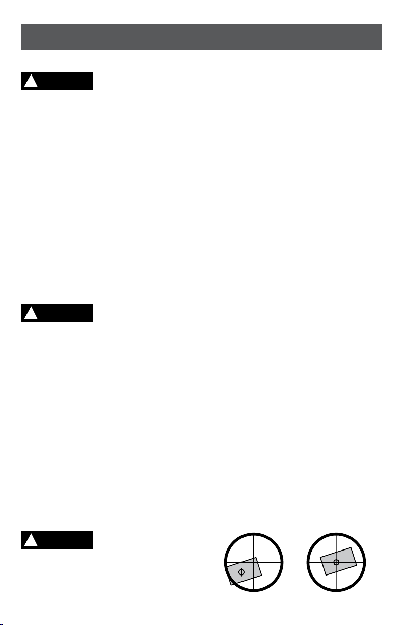
Positioning Directly Over Point Using
Optical Plummet
When looking through the eyepiece 11
the light path is reflected through center
of the instrument to the reference point (a
stake on the ground).
- Line up the tripod over the reference
point.
- Remove the plumb bob hanger from
the center stud of the tripod.
- Attach the instrument to the tripod.
- Level the instrument.
- Use the optical plummet to view the
reference point on the ground. Sight
through the optical plummet eyepiece
11 located beneath the telescope
eyepiece.
- Turn the optical plummet eyepiece 11
to bring the crosshairs into focus.
NOTE: The image seen in the eyepiece is
reversed left to right. This is important to
remember when shifting the instrument or
tripod to center over the reference point.
- Line up the crosshairs with the
reference point.

-10-
If necessary, the instrument can be shifted
by loosening the tripod center stud and
sliding the instrument from side to side for
proper positioning.
Positioning Directly Over Point Using
Laser Plummet
To switch ON the laser plummet, press
and release the
V
H
R
TILT
HOLD R / L
OSET V%
ON/OFF
HOLD R / L
OSET V%
ON/OFF
HOLDR/ L
OSET V%
ON/OFF
button. A laser point
will project through the center of the
instrument to the reference point (a stake
on the ground).
- Line up the tripod over the reference
point.
- Remove the plumb bob hanger from
the center stud of the tripod.
- Attach the instrument to the tripod.
- Level the instrument.
- Line up the laser point with the
reference point.
If necessary, the instrument can be
shifted by loosening the tripod center stud
and sliding the instrument from side to
side for proper positioning.
Leveling the Instrument
Center the instruments circular vial 8by
carefully extending or shortening the
tripod leg closest to the bubble. Caution:
Use only two legs. Repeat until alignment
is within 1/4-in (6 mm).
Set the instrument leveling screws. Turn
down the leveling screws 12 until firm
contact is made with the instrument base.
!CAUTION Do not overtighten the
leveling screws. It is
very possible to overtighten the leveling
screws. Only a firm contact between the
screws and the base is necessary. If the
instrument shifts on the base, turn down
the screw more firmly by hand.
Leveling the instrument so the vial bubble
remains centered through a 360° rotation
of the telescope is the most important
operation in preparing to use your
instrument.
When leveling your instrument, be sure
not to touch the tripod. Follow these
instructions carefully.
Use the tubular vial 17 to accurately level
the instrument. Unlock 13 and turn the
instrument so that the tubular vial 17 is
parallel to BC, any two leveling screws.
- Note the direction to turn the leveling
screws. When turning the two screws,
adjust them equally. The bubble will
move in the direction that your left
thumb turns.
-
To move the bubble to the right, turn the
B
leveling screw in and simultaneously
turn the
C
leveling screw in.
- To move the bubble left, move both
screws out simultaneously.
Once centered turn the instrument 90˚
over Aleveling screw and turn screw Ain
or out until bubble is centered.
Go back to the first position BC, and
repeat until the bubble is centered in both
positions. Then from position BC turn 180˚
to check the adjustment.
If the bubble stays centered or within ¼
division, you are leveled.
Next, check the ground point centering. If
you are not directly on the point, carefully
loosen the tripod fastener and move the
instrument on the tripod head in an x - y
-11-
direction. Do not rotate the instrument.
Recheck leveling and repeat until
instruments is level and over the ground
point at the same time. With practice, this
becomes easier.
Telescope Eyepiece Focus
Adjustment of Eyepiece
Direct the telescope to a bright
background. Turn the eyepiece ring so
that the crosshairs of the reticule are
clearly seen.
Elimination of Optical Parallax
Adjust the focusing ring to clearly see an
object on the reticule. Move your eyes up
and down to see if the image of the object
moves relative to the graduation lines.
If it does not move, there is no optical
parallax; otherwise turn the focusing ring
to eliminate the optical parallax.
Parameter Settings
Please enter all desired initial settings prior
to the first measurement.
Items in bold indicate factory settings.
Initial Setting Selection
1. Unit of Angle 360˚ / 400G / 6400
Unit A / Unit B / Unit C
2. Zenith Angle ZEN = = 0 / ZEN = = 90
3. Auto Power Off
Time
30 OFF / NO OFF
4. Min. Display dsp1 / dsp5
5. Tilt Sensor Switch TILT ON / TILT OFF
6. Indication of
Horizontal Angle
Position
No Beep / 90˚ Beep
Changing Parameter Settings
Press and hold
V
H
R
TILT
HOLD R / L
OSET V%
ON/OFF
HOLD R / L
OSET V%
ON/OFF
HOLDR/ L
OSET V%
ON/OFF
button and
V
H
R
TILT
HOLD R / L
OSET V%
ON/OFF
HOLD R / L
OSET V%
ON/OFF
HOLDR/ L
OSET V%
ON/OFF
button, and press
V
H
R
TILT
HOLD R / L
OSET V%
ON/OFF
HOLD R / L
OSET V%
ON/OFF
HOLDR/ L
OSET V%
ON/OFF
button.
Release
V
H
R
TILT
HOLD R / L
OSET V%
ON/OFF
HOLD R / L
OSET V%
ON/OFF
HOLDR/ L
OSET V%
ON/OFF
button when the full
character display appears and release
V
H
R
TILT
HOLD R / L
OSET V%
ON/OFF
HOLD R / L
OSET V%
ON/OFF
HOLDR/ L
OSET V%
ON/OFF
and
V
H
R
TILT
HOLD R / L
OSET V%
ON/OFF
HOLD R / L
OSET V%
ON/OFF
HOLDR/ L
OSET V%
ON/OFF
buttons when four
beeps are heard. The instrument enters
into its initial setup mode and the LCD
displays:
V
H
R
TILT
HOLD R / L
OSET V%
ON/OFF
SET
ZEN==90
VERTICAL
SET
30 OFF
AUTO OFF
SET
DSP 1
SET
TILT ON
SET
NO BEEP
TILT
90°00’ 10”
359°59’49”
V
H
R
TILT
TILT
359°59’49”
V
H
R
TILT
65°59’35”
359°59’49”
V
H
R
TILT
44.537%
359°59’49”
V
H
R
TILT
92°26’16”
359°59’49”
V
H
R
TILT
80°08’16”
359°59’49”
V
H
R
TILT
90°00’02”
359°59’49”
V
H
R
TILT
90°00’02”
0°00’00”
V
H
R
TILT
90°00’02”
3°03’05”
V
H
R
SET 0
FACE - 1
V
96°28’48”
FACE - 1
V
272°36’06”
FACE - 2
V
90°00’02”
150°36’10”
V
TILT
90°00’02”
356°65’55”
V
H
R
TILT
90°00’02”
356°65’55”
V
H
L
TILT
90°00’02”
0°00’00”
V
H
R
TILT
90°00’02”
45°26’10”
V
H
R
TILT
OFF
45°26’10”
V
H
R
TILT
SET 0
356°65’55”
V
H
R
SET
360° ’ ”
UNIT A
TILT
SET 0
150°36’ 10”
V
H
R
• Press
V
H
R
TILT
HOLD R / L
OSET V%
ON/OFF
HOLD R / L
OSET V%
ON/OFF
HOLDR/ L
OSET V%
ON/OFF
button or
V
H
R
TILT
HOLD R / L
OSET V%
ON/OFF
HOLD R / L
OSET V%
ON/OFF
HOLDR/ L
OSET V%
ON/OFF
button to
change screens for selecting options.
• Press
V
H
R
TILT
HOLD R / L
OSET V%
ON/OFF
HOLD R / L
OSET V%
ON/OFF
HOLDR/ L
OSET V%
ON/OFF
button for selecting specific
content in the options.
• Finally, press
V
H
R
TILT
HOLD R / L
OSET V%
ON/OFF
HOLD R / L
OSET V%
ON/OFF
HOLDR/ L
OSET V%
ON/OFF
button to confirm
and enter into angle measuring
mode.
Unit of Angle
• UNIT A: 360˚ (Degree)
• UNIT B: 400 (GON)
• UNIT C: 6400 (Mil)
Zero Position of Vertical Angle
• ZEN == 0 : Zenith is 0°
• ZEN == 90 : Zenith is 90°
V
H
R
TILT
HOLD R / L
OSET V%
ON/OFF
SET
ZEN==90
VERTICAL
SET
30 OFF
AUTO OFF
SET
DSP 1
SET
TILT ON
SET
NO BEEP
TILT
90°00’ 10”
359°59’49”
V
H
R
TILT
TILT
359°59’49”
V
H
R
TILT
65°59’35”
359°59’49”
V
H
R
TILT
44.537%
359°59’49”
V
H
R
TILT
92°26’16”
359°59’49”
V
H
R
TILT
80°08’16”
359°59’49”
V
H
R
TILT
90°00’02”
359°59’49”
V
H
R
TILT
90°00’02”
0°00’00”
V
H
R
TILT
90°00’02”
3°03’05”
V
H
R
SET 0
FACE - 1
V
96°28’48”
FACE - 1
V
272°36’06”
FACE - 2
V
90°00’02”
150°36’10”
V
TILT
90°00’02”
356°65’55”
V
H
R
TILT
90°00’02”
356°65’55”
V
H
L
TILT
90°00’02”
0°00’00”
V
H
R
TILT
90°00’02”
45°26’10”
V
H
R
TILT
OFF
45°26’10”
V
H
R
TILT
SET 0
356°65’55”
V
H
R
SET
360° ’ ”
UNIT A
TILT
SET 0
150°36’ 10”
V
H
R
Auto Power Off Time
• NO OFF: Auto power off disabled
• 30 OFF: Turns power off if
inactive for 30 min
V
H
R
TILT
HOLD R / L
OSET V%
ON/OFF
SET
ZEN==90
VERTICAL
SET
30 OFF
AUTO OFF
SET
DSP 1
SET
TILT ON
SET
NO BEEP
TILT
90°00’ 10”
359°59’49”
V
H
R
TILT
TILT
359°59’49”
V
H
R
TILT
65°59’35”
359°59’49”
V
H
R
TILT
44.537%
359°59’49”
V
H
R
TILT
92°26’16”
359°59’49”
V
H
R
TILT
80°08’16”
359°59’49”
V
H
R
TILT
90°00’02”
359°59’49”
V
H
R
TILT
90°00’02”
0°00’00”
V
H
R
TILT
90°00’02”
3°03’05”
V
H
R
SET 0
FACE - 1
V
96°28’48”
FACE - 1
V
272°36’06”
FACE - 2
V
90°00’02”
150°36’10”
V
TILT
90°00’02”
356°65’55”
V
H
R
TILT
90°00’02”
356°65’55”
V
H
L
TILT
90°00’02”
0°00’00”
V
H
R
TILT
90°00’02”
45°26’10”
V
H
R
TILT
OFF
45°26’10”
V
H
R
TILT
SET 0
356°65’55”
V
H
R
SET
360° ’ ”
UNIT A
TILT
SET 0
150°36’ 10”
V
H
R
Minimum Display
• DSP 1: Minimum display is 1”
• DSP 5: Minimum display is 5”
V
H
R
TILT
HOLD R / L
OSET V%
ON/OFF
SET
ZEN==90
VERTICAL
SET
30 OFF
AUTO OFF
SET
DSP 1
SET
TILT ON
SET
NO BEEP
TILT
90°00’ 10”
359°59’49”
V
H
R
TILT
TILT
359°59’49”
V
H
R
TILT
65°59’35”
359°59’49”
V
H
R
TILT
44.537%
359°59’49”
V
H
R
TILT
92°26’16”
359°59’49”
V
H
R
TILT
80°08’16”
359°59’49”
V
H
R
TILT
90°00’02”
359°59’49”
V
H
R
TILT
90°00’02”
0°00’00”
V
H
R
TILT
90°00’02”
3°03’05”
V
H
R
SET 0
FACE - 1
V
96°28’48”
FACE - 1
V
272°36’06”
FACE - 2
V
90°00’02”
150°36’10”
V
TILT
90°00’02”
356°65’55”
V
H
R
TILT
90°00’02”
356°65’55”
V
H
L
TILT
90°00’02”
0°00’00”
V
H
R
TILT
90°00’02”
45°26’10”
V
H
R
TILT
OFF
45°26’10”
V
H
R
TILT
SET 0
356°65’55”
V
H
R
SET
360° ’ ”
UNIT A
TILT
SET 0
150°36’ 10”
V
H
R
-12-
Setting of Tilt Sensor
• V TILT ON: Turn on the tilt sensor
• V TILT OFF: Turn off the tilt sensor
V
H
R
TILT
HOLD R / L
OSET V%
ON/OFF
SET
ZEN==90
VERTICAL
SET
30 OFF
AUTO OFF
SET
DSP 1
SET
TILT ON
SET
NO BEEP
TILT
90°00’ 10”
359°59’49”
V
H
R
TILT
TILT
359°59’49”
V
H
R
TILT
65°59’35”
359°59’49”
V
H
R
TILT
44.537%
359°59’49”
V
H
R
TILT
92°26’16”
359°59’49”
V
H
R
TILT
80°08’16”
359°59’49”
V
H
R
TILT
90°00’02”
359°59’49”
V
H
R
TILT
90°00’02”
0°00’00”
V
H
R
TILT
90°00’02”
3°03’05”
V
H
R
SET 0
FACE - 1
V
96°28’48”
FACE - 1
V
272°36’06”
FACE - 2
V
90°00’02”
150°36’10”
V
TILT
90°00’02”
356°65’55”
V
H
R
TILT
90°00’02”
356°65’55”
V
H
L
TILT
90°00’02”
0°00’00”
V
H
R
TILT
90°00’02”
45°26’10”
V
H
R
TILT
OFF
45°26’10”
V
H
R
TILT
SET 0
356°65’55”
V
H
R
SET
360° ’ ”
UNIT A
TILT
SET 0
150°36’ 10”
V
H
R
Indication of Horizontal Angle
• NO BEEP: Horizontal angle indication
disabled
• 90 BEEP: Sounds beep when the
instrument is close to 0˚, 90°, 180˚
and 270°
V
H
R
TILT
HOLD R / L
OSET V%
ON/OFF
SET
ZEN==90
VERTICAL
SET
30 OFF
AUTO OFF
SET
DSP 1
SET
TILT ON
SET
NO BEEP
TILT
90°00’ 10”
359°59’49”
V
H
R
TILT
TILT
359°59’49”
V
H
R
TILT
65°59’35”
359°59’49”
V
H
R
TILT
44.537%
359°59’49”
V
H
R
TILT
92°26’16”
359°59’49”
V
H
R
TILT
80°08’16”
359°59’49”
V
H
R
TILT
90°00’02”
359°59’49”
V
H
R
TILT
90°00’02”
0°00’00”
V
H
R
TILT
90°00’02”
3°03’05”
V
H
R
SET 0
FACE - 1
V
96°28’48”
FACE - 1
V
272°36’06”
FACE - 2
V
90°00’02”
150°36’10”
V
TILT
90°00’02”
356°65’55”
V
H
R
TILT
90°00’02”
356°65’55”
V
H
L
TILT
90°00’02”
0°00’00”
V
H
R
TILT
90°00’02”
45°26’10”
V
H
R
TILT
OFF
45°26’10”
V
H
R
TILT
SET 0
356°65’55”
V
H
R
SET
360° ’ ”
UNIT A
TILT
SET 0
150°36’ 10”
V
H
R
Start Up
Press and hold
V
H
R
TILT
HOLD R / L
OSET V%
ON/OFF
HOLD R / L
OSET V%
ON/OFF
HOLDR/ L
OSET V%
ON/OFF
button. Release
V
H
R
TILT
HOLD R / L
OSET V%
ON/OFF
HOLD R / L
OSET V%
ON/OFF
HOLDR/ L
OSET V%
ON/OFF
button when the full character
display appears. The LCD displays:
V
H
R
TILT
HOLD R / L
OSET V%
ON/OFF
SET
ZEN==90
VERTICAL
SET
30 OFF
AUTO OFF
SET
DSP 1
SET
TILT ON
SET
NO BEEP
TILT
90°00’ 10”
359°59’49”
V
H
R
TILT
TILT
359°59’49”
V
H
R
TILT
65°59’35”
359°59’49”
V
H
R
TILT
44.537%
359°59’49”
V
H
R
TILT
92°26’16”
359°59’49”
V
H
R
TILT
80°08’16”
359°59’49”
V
H
R
TILT
90°00’02”
359°59’49”
V
H
R
TILT
90°00’02”
0°00’00”
V
H
R
TILT
90°00’02”
3°03’05”
V
H
R
SET 0
FACE - 1
V
96°28’48”
FACE - 1
V
272°36’06”
FACE - 2
V
90°00’02”
150°36’10”
V
TILT
90°00’02”
356°65’55”
V
H
R
TILT
90°00’02”
356°65’55”
V
H
L
TILT
90°00’02”
0°00’00”
V
H
R
TILT
90°00’02”
45°26’10”
V
H
R
TILT
OFF
45°26’10”
V
H
R
TILT
SET 0
356°65’55”
V
H
R
SET
360° ’ ”
UNIT A
TILT
SET 0
150°36’ 10”
V
H
R
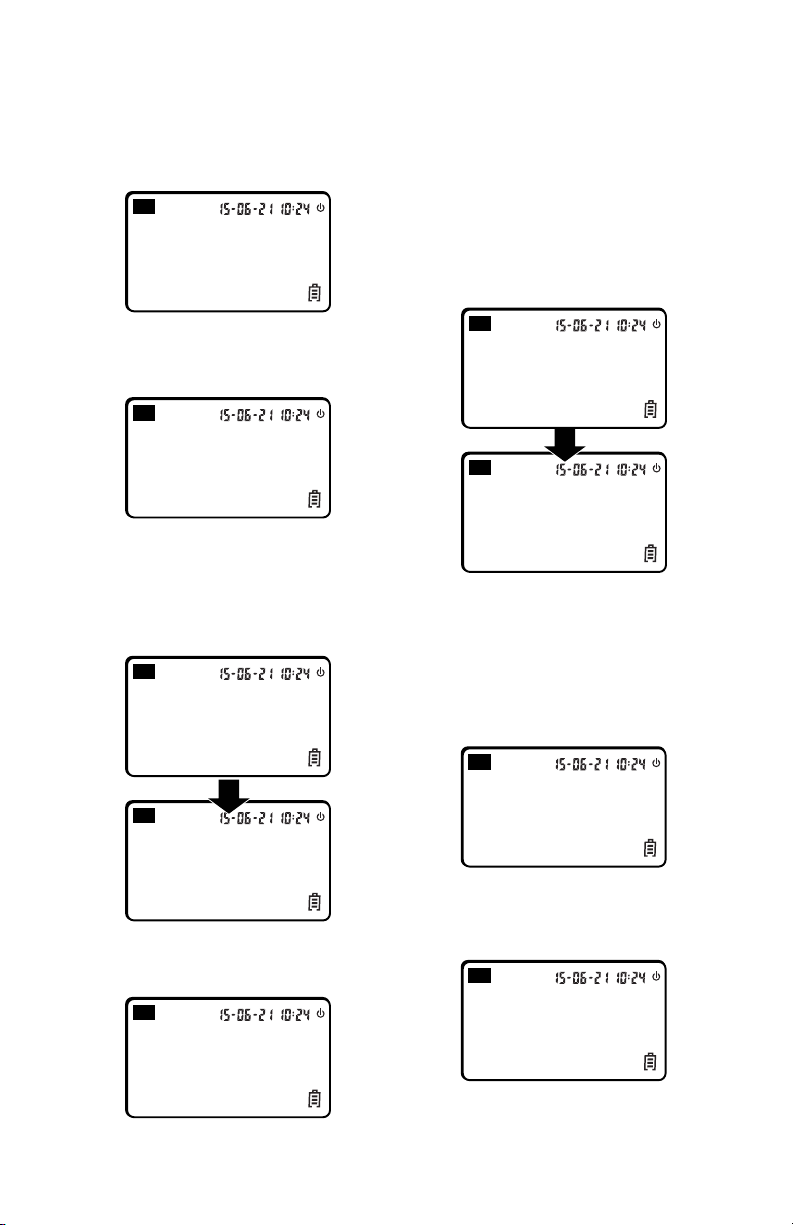
• Move the telescope up and down
when the instrument is at the normal
position. The beeper beeps and the
LCD displays the vertical angle. The
instrument enters into measuring
mode.
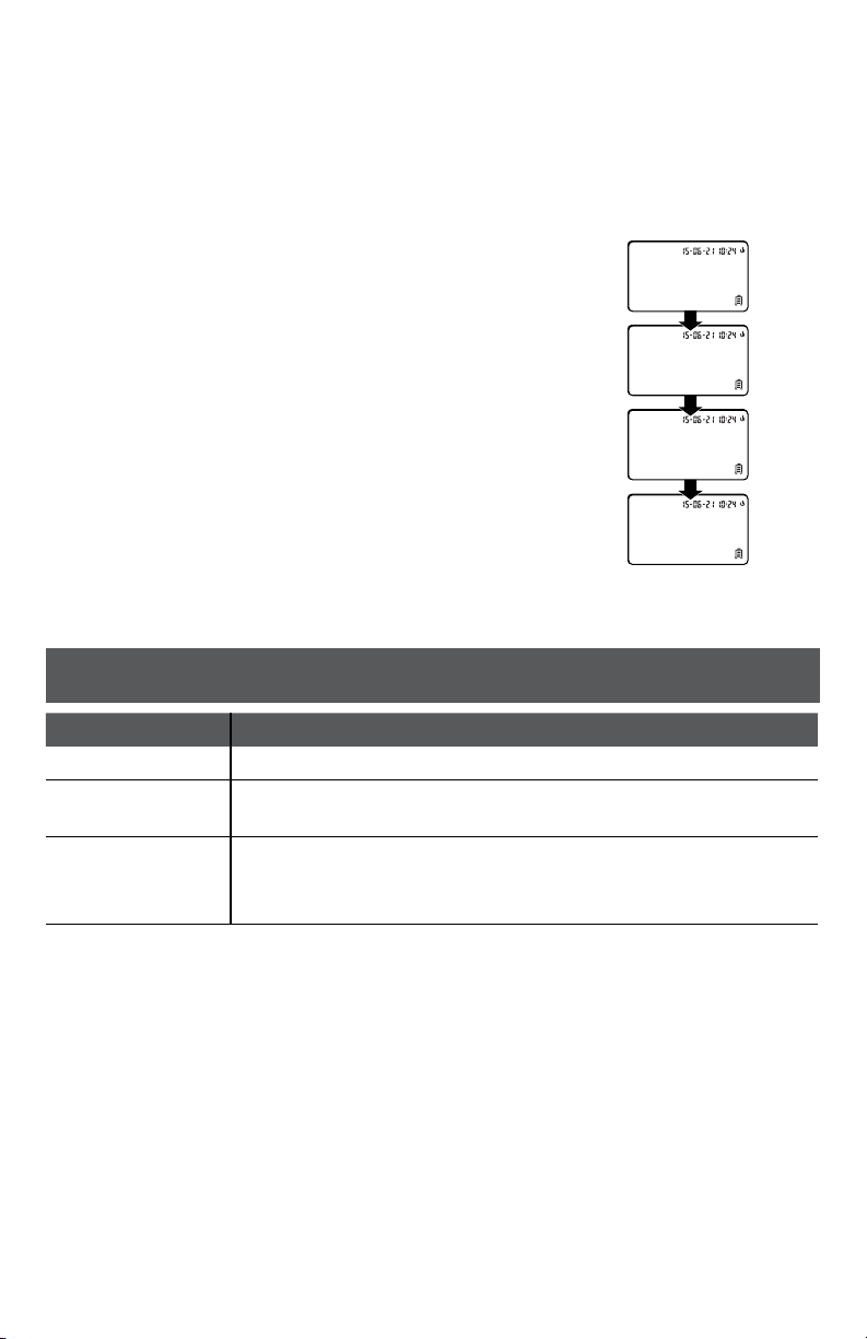
• After the power is switched on and
the instrument has entered into
measuring mode, the battery level is
indicated by the battery symbol in
the lower right corner of LCD.
• If all of the three squares are
displayed, the battery is fully charged.
• Decreasing squares indicates
reduction of charge.
• If the battery symbol blinks, the
battery is low and needs recharging
or replacing.
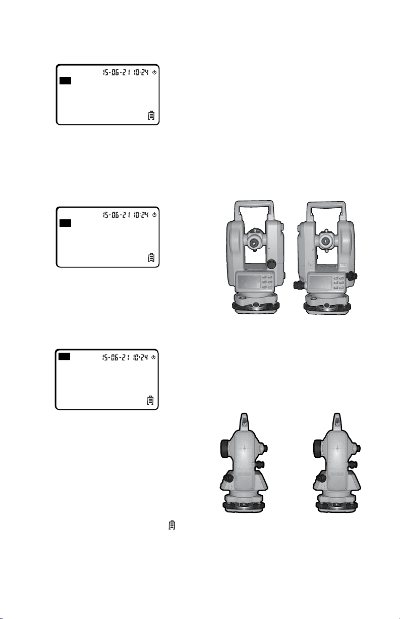
Measurement of Angle
Observing in the “Normal” and “Reverse”
Positions of the Telescope
The normal, or direct, position of the
telescope refers to observation with
the vertical circle being on the left. The
reverse position refers to observation
with the vertical circle being on the right.
The mechanical errors can be offset by
averaging the values measured in the
normal and reverse positions.
Normal Reverse
Measurement of Vertical Angle
• 0° angle position can be set as
follows in the initial setting:
ZEN==0
(Zenith 0°)
ZEN==90
(Zenith 90°)
90° 270°
180°
0°
0° 180°
270°
90°
-13-
Compensation of the Tilt Sensor to
Vertical Angle
• If the instrument is inclined
within ±3’, the tilt sensor can
compensate the vertical angle.
V
H
R
TILT
HOLD R / L
OSET V%
ON/OFF
SET
ZEN==90
VERTICAL
SET
30 OFF
AUTO OFF
SET
DSP 1
SET
TILT ON
SET
NO BEEP
TILT
90°00’ 10”
359°59’49”
V
H
R
TILT
TILT
359°59’49”
V
H
R
TILT
65°59’35”
359°59’49”
V
H
R
TILT
44.537%
359°59’49”
V
H
R
TILT
92°26’16”
359°59’49”
V
H
R
TILT
80°08’16”
359°59’49”
V
H
R
TILT
90°00’02”
359°59’49”
V
H
R
TILT
90°00’02”
0°00’00”
V
H
R
TILT
90°00’02”
3°03’05”
V
H
R
SET 0
FACE - 1
V
96°28’48”
FACE - 1
V
272°36’06”
FACE - 2
V
90°00’02”
150°36’10”
V
TILT
90°00’02”
356°65’55”
V
H
R
TILT
90°00’02”
356°65’55”
V
H
L
TILT
90°00’02”
0°00’00”
V
H
R
TILT
90°00’02”
45°26’10”
V
H
R
TILT
OFF
45°26’10”
V
H
R
TILT
SET 0
356°65’55”
V
H
R
SET
360° ’ ”
UNIT A
TILT
SET 0
150°36’ 10”
V
H
R
• If the inclination is greater than
±3’, the instrument will display
TILT as shown in the figure.
V
H
R
TILT
HOLD R / L
OSET V%
ON/OFF
SET
ZEN==90
VERTICAL
SET
30 OFF
AUTO OFF
SET
DSP 1
SET
TILT ON
SET
NO BEEP
TILT
90°00’ 10”
359°59’49”
V
H
R
TILT
TILT
359°59’49”
V
H
R
TILT
65°59’35”
359°59’49”
V
H
R
TILT
44.537%
359°59’49”
V
H
R
TILT
92°26’16”
359°59’49”
V
H
R
TILT
80°08’16”
359°59’49”
V
H
R
TILT
90°00’02”
359°59’49”
V
H
R
TILT
90°00’02”
0°00’00”
V
H
R
TILT
90°00’02”
3°03’05”
V
H
R
SET 0
FACE - 1
V
96°28’48”
FACE - 1
V
272°36’06”
FACE - 2
V
90°00’02”
150°36’10”
V
TILT
90°00’02”
356°65’55”
V
H
R
TILT
90°00’02”
356°65’55”
V
H
L
TILT
90°00’02”
0°00’00”
V
H
R
TILT
90°00’02”
45°26’10”
V
H
R
TILT
OFF
45°26’10”
V
H
R
TILT
SET 0
356°65’55”
V
H
R
SET
360° ’ ”
UNIT A
TILT
SET 0
150°36’ 10”
V
H
R
Display of Slope
• Press
V
H
R
TILT
HOLD R / L
OSET V%
ON/OFF
HOLD R / L
OSET V%
ON/OFF
HOLDR/ L
OSET V%
ON/OFF
button, the vertical
angle display is changed to slope
display.
V
H
R
TILT
HOLD R / L
OSET V%
ON/OFF
SET
ZEN==90
VERTICAL
SET
30 OFF
AUTO OFF
SET
DSP 1
SET
TILT ON
SET
NO BEEP
TILT
90°00’ 10”
359°59’49”
V
H
R
TILT
TILT
359°59’49”
V
H
R
TILT
65°59’35”
359°59’49”
V
H
R
TILT
44.537%
359°59’49”
V
H
R
TILT
92°26’16”
359°59’49”
V
H
R
TILT
80°08’16”
359°59’49”
V
H
R
TILT
90°00’02”
359°59’49”
V
H
R
TILT
90°00’02”
0°00’00”
V
H
R
TILT
90°00’02”
3°03’05”
V
H
R
SET 0
FACE - 1
V
96°28’48”
FACE - 1
V
272°36’06”
FACE - 2
V
90°00’02”
150°36’10”
V
TILT
90°00’02”
356°65’55”
V
H
R
TILT
90°00’02”
356°65’55”
V
H
L
TILT
90°00’02”
0°00’00”
V
H
R
TILT
90°00’02”
45°26’10”
V
H
R
TILT
OFF
45°26’10”
V
H
R
TILT
SET 0
356°65’55”
V
H
R
SET
360° ’ ”
UNIT A
TILT
SET 0
150°36’ 10”
V
H
R
• Press
V
H
R
TILT
HOLD R / L
OSET V%
ON/OFF
HOLD R / L
OSET V%
ON/OFF
HOLDR/ L
OSET V%
ON/OFF
button again, the
vertical angle display is resumed.
V
H
R
TILT
HOLD R / L
OSET V%
ON/OFF
SET
ZEN==90
VERTICAL
SET
30 OFF
AUTO OFF
SET
DSP 1
SET
TILT ON
SET
NO BEEP
TILT
90°00’ 10”
359°59’49”
V
H
R
TILT
TILT
359°59’49”
V
H
R
TILT
65°59’35”
359°59’49”
V
H
R
TILT
44.537%
359°59’49”
V
H
R
TILT
92°26’16”
359°59’49”
V
H
R
TILT
80°08’16”
359°59’49”
V
H
R
TILT
90°00’02”
359°59’49”
V
H
R
TILT
90°00’02”
0°00’00”
V
H
R
TILT
90°00’02”
3°03’05”
V
H
R
SET 0
FACE - 1
V
96°28’48”
FACE - 1
V
272°36’06”
FACE - 2
V
90°00’02”
150°36’10”
V
TILT
90°00’02”
356°65’55”
V
H
R
TILT
90°00’02”
356°65’55”
V
H
L
TILT
90°00’02”
0°00’00”
V
H
R
TILT
90°00’02”
45°26’10”
V
H
R
TILT
OFF
45°26’10”
V
H
R
TILT
SET 0
356°65’55”
V
H
R
SET
360° ’ ”
UNIT A
TILT
SET 0
150°36’ 10”
V
H
R
Note: When vertical angle is converted
to slope, the precision of the slope
reading is two digits after the decimal.
The value of slope is displayed only
within ± 45° (100%). There will be no
slope display exceeding this range.
Measurement of Horizontal Angle
• Reset horizontal angle.
Press
V
H
R
TILT
HOLD R / L
OSET V%
ON/OFF
HOLD R / L
OSET V%
ON/OFF
HOLDR/ L
OSET V%
ON/OFF
button, the
horizontal angle returns to zero.
V
H
R
TILT
HOLD R / L
OSET V%
ON/OFF
SET
ZEN==90
VERTICAL
SET
30 OFF
AUTO OFF
SET
DSP 1
SET
TILT ON
SET
NO BEEP
TILT
90°00’ 10”
359°59’49”
V
H
R
TILT
TILT
359°59’49”
V
H
R
TILT
65°59’35”
359°59’49”
V
H
R
TILT
44.537%
359°59’49”
V
H
R
TILT
92°26’16”
359°59’49”
V
H
R
TILT
80°08’16”
359°59’49”
V
H
R
TILT
90°00’02”
359°59’49”
V
H
R
TILT
90°00’02”
0°00’00”
V
H
R
TILT
90°00’02”
3°03’05”
V
H
R
SET 0
FACE - 1
V
96°28’48”
FACE - 1
V
272°36’06”
FACE - 2
V
90°00’02”
150°36’10”
V
TILT
90°00’02”
356°65’55”
V
H
R
TILT
90°00’02”
356°65’55”
V
H
L
TILT
90°00’02”
0°00’00”
V
H
R
TILT
90°00’02”
45°26’10”
V
H
R
TILT
OFF
45°26’10”
V
H
R
TILT
SET 0
356°65’55”
V
H
R
SET
360° ’ ”
UNIT A
TILT
SET 0
150°36’ 10”
V
H
R
• Selecting the direction of
horizontal angle measurement.
Press
V
H
R
TILT
HOLD R / L
OSET V%
ON/OFF
HOLD R / L
OSET V%
ON/OFF
HOLDR/ L
OSET V%
ON/OFF
button to change
the direction of measurement of
the horizontal angle.
When “HR’ is displayed, the angle
increases with clockwise turning.
V
H
R
TILT
HOLD R / L
OSET V%
ON/OFF
SET
ZEN==90
VERTICAL
SET
30 OFF
AUTO OFF
SET
DSP 1
SET
TILT ON
SET
NO BEEP
TILT
90°00’ 10”
359°59’49”
V
H
R
TILT
TILT
359°59’49”
V
H
R
TILT
65°59’35”
359°59’49”
V
H
R
TILT
44.537%
359°59’49”
V
H
R
TILT
92°26’16”
359°59’49”
V
H
R
TILT
80°08’16”
359°59’49”
V
H
R
TILT
90°00’02”
359°59’49”
V
H
R
TILT
90°00’02”
0°00’00”
V
H
R
TILT
90°00’02”
3°03’05”
V
H
R
SET 0
FACE - 1
V
96°28’48”
FACE - 1
V
272°36’06”
FACE - 2
V
90°00’02”
150°36’10”
V
TILT
90°00’02”
356°65’55”
V
H
R
TILT
90°00’02”
356°65’55”
V
H
L
TILT
90°00’02”
0°00’00”
V
H
R
TILT
90°00’02”
45°26’10”
V
H
R
TILT
OFF
45°26’10”
V
H
R
TILT
SET 0
356°65’55”
V
H
R
SET
360° ’ ”
UNIT A
TILT
SET 0
150°36’ 10”
V
H
R
When “HL” is displayed, the angle
increases with counterclockwise
turning.
V
H
R
TILT
HOLD R / L
OSET V%
ON/OFF
SET
ZEN==90
VERTICAL
SET
30 OFF
AUTO OFF
SET
DSP 1
SET
TILT ON
SET
NO BEEP
TILT
90°00’ 10”
359°59’49”
V
H
R
TILT
TILT
359°59’49”
V
H
R
TILT
65°59’35”
359°59’49”
V
H
R
TILT
44.537%
359°59’49”
V
H
R
TILT
92°26’16”
359°59’49”
V
H
R
TILT
80°08’16”
359°59’49”
V
H
R
TILT
90°00’02”
359°59’49”
V
H
R
TILT
90°00’02”
0°00’00”
V
H
R
TILT
90°00’02”
3°03’05”
V
H
R
SET 0
FACE - 1
V
96°28’48”
FACE - 1
V
272°36’06”
FACE - 2
V
90°00’02”
150°36’10”
V
TILT
90°00’02”
356°65’55”
V
H
R
TILT
90°00’02”
356°65’55”
V
H
L
TILT
90°00’02”
0°00’00”
V
H
R
TILT
90°00’02”
45°26’10”
V
H
R
TILT
OFF
45°26’10”
V
H
R
TILT
SET 0
356°65’55”
V
H
R
SET
360° ’ ”
UNIT A
TILT
SET 0
150°36’ 10”
V
H
R
-14-
• Holding the Horizontal Angle.
Press
V
H
R
TILT
HOLD R / L
OSET V%
ON/OFF
HOLD R / L
OSET V%
ON/OFF
HOLDR/ L
OSET V%
ON/OFF
button, the
horizontal angle will be held. The
reading of the horizontal angle
will remain unchanged even if the
direction of telescope is changed.
V
H
R
TILT
HOLD R / L
OSET V%
ON/OFF
SET
ZEN==90
VERTICAL
SET
30 OFF
AUTO OFF
SET
DSP 1
SET
TILT ON
SET
NO BEEP
TILT
90°00’ 10”
359°59’49”
V
H
R
TILT
TILT
359°59’49”
V
H
R
TILT
65°59’35”
359°59’49”
V
H
R
TILT
44.537%
359°59’49”
V
H
R
TILT
92°26’16”
359°59’49”
V
H
R
TILT
80°08’16”
359°59’49”
V
H
R
TILT
90°00’02”
359°59’49”
V
H
R
TILT
90°00’02”
0°00’00”
V
H
R
TILT
90°00’02”
3°03’05”
V
H
R
SET 0
FACE - 1
V
96°28’48”
FACE - 1
V
272°36’06”
FACE - 2
V
90°00’02”
150°36’10”
V
TILT
90°00’02”
356°65’55”
V
H
R
TILT
90°00’02”
356°65’55”
V
H
L
TILT
90°00’02”
0°00’00”
V
H
R
TILT
90°00’02”
45°26’10”
V
H
R
TILT
OFF
45°26’10”
V
H
R
TILT
SET 0
356°65’55”
V
H
R
SET
360° ’ ”
UNIT A
TILT
SET 0
150°36’ 10”
V
H
R
Press
V
H
R
TILT
HOLD R / L
OSET V%
ON/OFF
HOLD R / L
OSET V%
ON/OFF
HOLDR/ L
OSET V%
ON/OFF
button again,
the hold of horizontal angle is
released.
Turning Instrument Off
• Press
V
H
R
TILT
HOLD R / L
OSET V%
ON/OFF
HOLD R / L
OSET V%
ON/OFF
HOLDR/ L
OSET V%
ON/OFF
button, “OFF” will
be displayed at the position of
vertical angle display after a beep;
release
V
H
R
TILT
HOLD R / L
OSET V%
ON/OFF
HOLD R / L
OSET V%
ON/OFF
HOLDR/ L
OSET V%
ON/OFF
button, the
instrument is turned off.
V
H
R
TILT
HOLD R / L
OSET V%
ON/OFF
SET
ZEN==90
VERTICAL
SET
30 OFF
AUTO OFF
SET
DSP 1
SET
TILT ON
SET
NO BEEP
TILT
90°00’ 10”
359°59’49”
V
H
R
TILT
TILT
359°59’49”
V
H
R
TILT
65°59’35”
359°59’49”
V
H
R
TILT
44.537%
359°59’49”
V
H
R
TILT
92°26’16”
359°59’49”
V
H
R
TILT
80°08’16”
359°59’49”
V
H
R
TILT
90°00’02”
359°59’49”
V
H
R
TILT
90°00’02”
0°00’00”
V
H
R
TILT
90°00’02”
3°03’05”
V
H
R
SET 0
FACE - 1
V
96°28’48”
FACE - 1
V
272°36’06”
FACE - 2
V
90°00’02”
150°36’10”
V
TILT
90°00’02”
356°65’55”
V
H
R
TILT
90°00’02”
356°65’55”
V
H
L
TILT
90°00’02”
0°00’00”
V
H
R
TILT
90°00’02”
45°26’10”
V
H
R
TILT
OFF
45°26’10”
V
H
R
TILT
SET 0
356°65’55”
V
H
R
SET
360° ’ ”
UNIT A
TILT
SET 0
150°36’ 10”
V
H
R
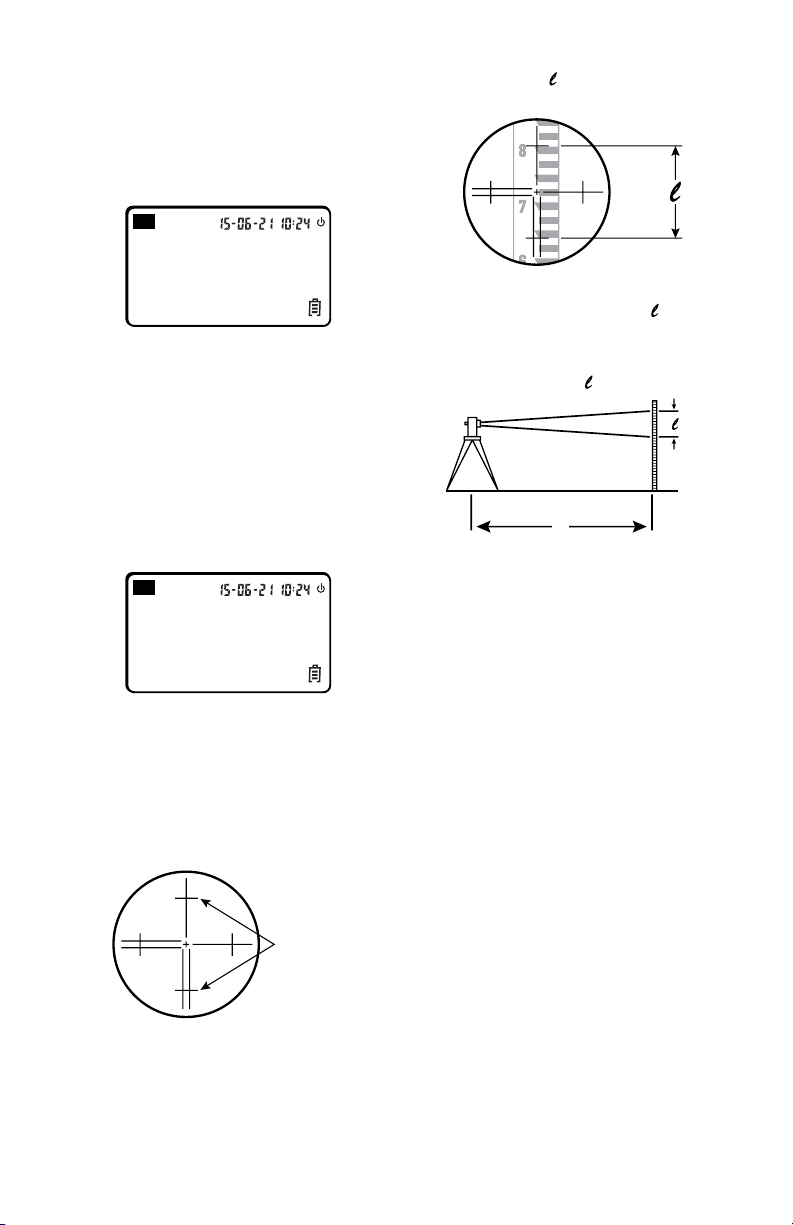
Measuring Distance Using the
Stadia Method
Distance measurement can be done
using the stadia hairs of the reticle.
Ground
Target
Stadia
Hairs
half the
distance
A
A´
A
A´
AB
L
Read the length “ ” of a level rod
shown between the stadia hairs.
Ground
Target
Stadia
Hairs
half the
distance
A
A´
A
A´
AB
L
The distance to the target is “ ”
multiplied by 100. The distance
between point A and point B is L.
L = 100 x “ ”
Ground
Target
Stadia
Hairs
half the
distance
A
A´
A
A´
AB
L
-15-
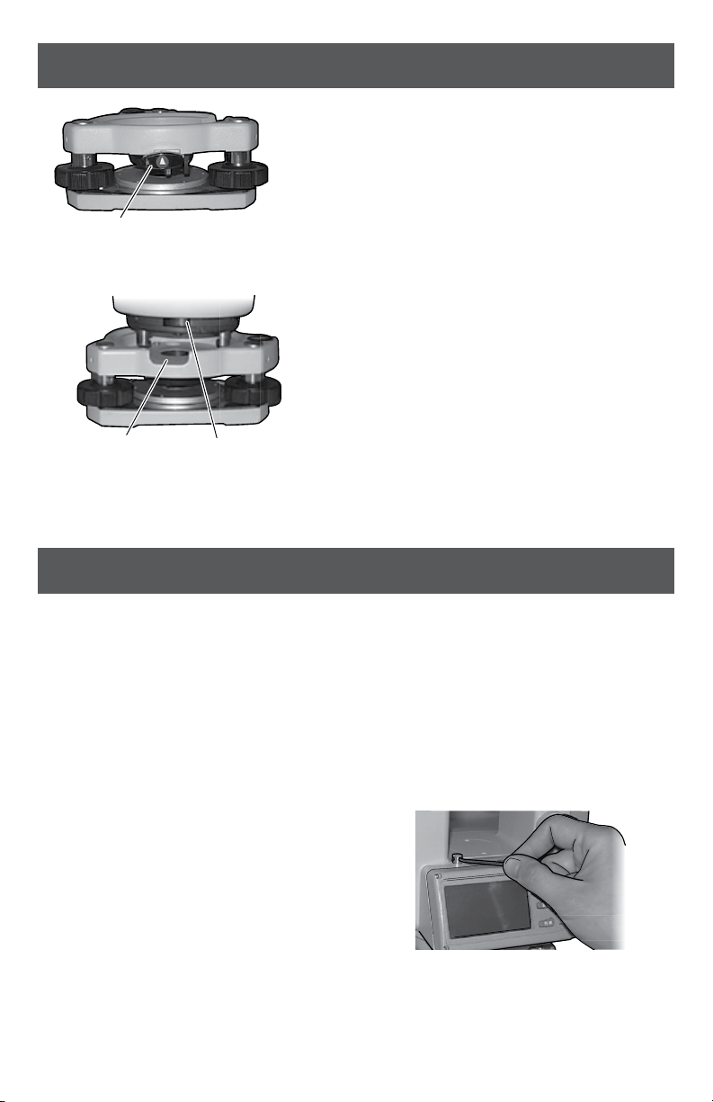
TRIBRACH
CHECKS AND ADJUSTMENTS
Removal
• Turn the screw on the tribrach locking
Lever 13 outward using a flat screw driver
to its stop.
• Turn the tribrach locking lever 13 180°
counterclockwise. Holding the base with
one hand, take the main body off the base.
Attachment
• Turn the tribrach locking lever 13
counterclockwise until it reaches the
position limit.
Align the positioning block on the main
body of the instrument to the notch on the
base. Install the main body onto the base.
• Turn the tribrach locking lever 13 clockwise
until it reaches the position limit so that the
‘v’ mark points downward.
• Turn the screw inward until it hits its stop.
13
Notch Positioning
Block
13
Notch Positioning
Block
When attempting to check and adjust the
instrument, corrections must be made in
a certain order to ensure the adjustments
are correct.
Order of adjustment:
1. Check and adjust the tubular plate
vial 17.
2. Check and adjust the circular leveling
vial 8.
3. Check and adjust the optical
plummet 11 (DT8-05P & DT8-05LS)
Always recheck your adjustments. We
recommend that any adjustments, other
than those above, be done by a qualified
repair technician.
Tubular plate vial
A. Place the plate vial parallel to the
leveling screws, A and B. Center the
bubble using these two level screws.
B. Turn the instrument 90° and center
the bubble using leveling screw C.
C.
Return to the original position in step
A. Recheck the bubble and center as
necessary. Rotate the instrument 180°.
The bubble should still be centered in
the vial. If not, go to next step.
D. Using the adjusting pin, provided
in the case, turn the screw until the
bubble moves halfway back to its
original position.
E. Return the instrument to its original
position and repeat steps A through
C. Repeat these steps until the
bubble stays centered in all positions.
-16-
Circular Leveling Vial
If the circular vial is centered after leveling
the plate vial, then no further adjustment
is necessary. If not, proceed with the
following adjustment.
A. Using the adjusting pin, provided in
the case, turn the adjusting screws
until the bubble is centered in the vial.
Do not over tighten the adjusting screws
B. Loosen one screw by turning it 1/4
turn, then tighten the other screw by
1/4 turn.
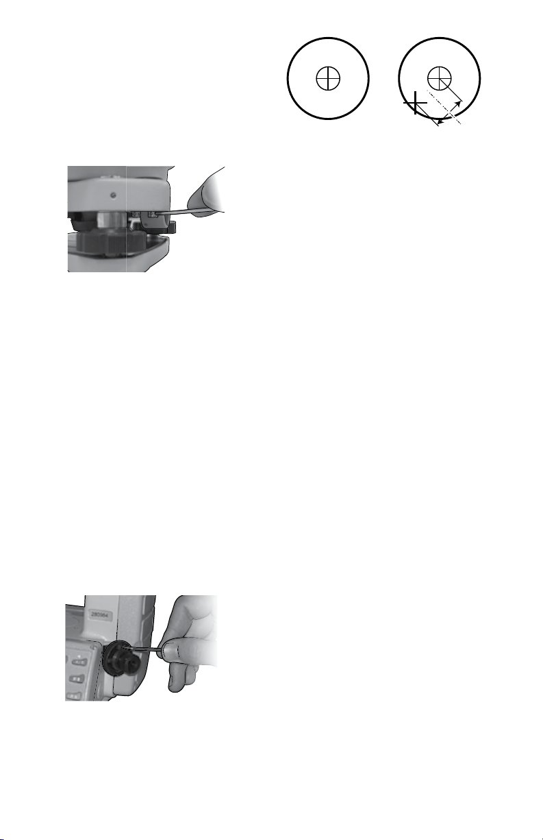
Optical Plummet
This adjustment is required to make
the line of sight of the optical plummet
coincide with the vertical axis.
A. Point the optical plummet at a ground
target. This can be done by adjusting
the level screws or by loosening
the instrument fastening screw and
moving the instrument over the
target.
B. Turn the instrument 180° and
re-sight the target through the optical
plummet. If the target is still centered,
no adjustment is necessary. If not, go
to next step.
D. Using the adjusting pin, provided in
the case, turn the reticle adjusting
screws until half the displacement has
been removed. Loosen one screw
1/4 turn, then tighten the opposing
screw 1/4 turn.
Ground
Target
Stadia
Hairs
half the
distance
A
A´
A
A´
AB
L
E. Repeat steps A through D until there
is no displacement of the target when
the instrument is turned about its
vertical axis.
Collimation Error
• Attach the instrument on a tripod and
precisely level.
• Aim at point A in the distance with the
normal, direct position of telescope.
Record the reading of the horizontal
angle - HR-DIRECT.
• Using the reverse position of the
telescope, take the reading of the
horizontal angle - HR-REVERSE, then:
Collimation Error C = (HR-Direct -—
HR-Reverse ± 180°)/2
If C <10”, no adjustment is required.
If C >10”, the following adjustment is
required:
• Adjust the horizontal fine motion in
the reverse position of the telescope
so that the reverse reading HR-Rev =
HR-Rev + C.
• Remove the protective cover of the
reticule of the telescope and adjust
both the left and right adjusting
screws so that the vertical hair of the
reticule coincides with object A.
• Repeat the steps until acceptable
condition is reached.
-17-
Index Error of Vertical Circle
• Attach the instrument on a tripod and precisely level.
• Aim at any object, point P, in the normal position and
take the reading of vertical angle - V-Direct.
• Turn the telescope to the reverse position and aim it at
point P again. Take the reading of other vertical angle -
V-Rev.
If (V-Direct + V-Rev) - 360°= ≤15”, no adjustment is required.
Otherwise, perform adjustment as follows:
A. Press and hold
V
H
R
TILT
HOLD R / L
OSET V%
ON/OFF
HOLD R / L
OSET V%
ON/OFF
HOLDR/ L
OSET V%
ON/OFF
and
V
H
R
TILT
HOLD R / L
OSET V%
ON/OFF
HOLD R / L
OSET V%
ON/OFF
HOLDR/ L
OSET V%
ON/OFF
buttons while
pressing
V
H
R
TILT
HOLD R / L
OSET V%
ON/OFF
HOLD R / L
OSET V%
ON/OFF
HOLDR/ L
OSET V%
ON/OFF
button.
B. Release
V
H
R
TILT
HOLD R / L
OSET V%
ON/OFF
HOLD R / L
OSET V%
ON/OFF
HOLDR/ L
OSET V%
ON/OFF
button when full character display
appears and then release
V
H
R
TILT
HOLD R / L
OSET V%
ON/OFF
HOLD R / L
OSET V%
ON/OFF
HOLDR/ L
OSET V%
ON/OFF
and
V
H
R
TILT
HOLD R / L
OSET V%
ON/OFF
HOLD R / L
OSET V%
ON/OFF
HOLDR/ L
OSET V%
ON/OFF
buttons
when four beeps are heard.
C. Swing the telescope near horizontal with the instrument
in the normal position.
D. Allow the vertical angle to reset after it crosses zero.
Aim the telescope in the normal position at object P and
press
V
H
R
TILT
HOLD R / L
OSET V%
ON/OFF
HOLD R / L
OSET V%
ON/OFF
HOLDR/ L
OSET V%
ON/OFF
to confirm.
V
H
R
TILT
HOLD R / L
OSET V%
ON/OFF
SET
ZEN==90
VERTICAL
SET
30 OFF
AUTO OFF
SET
DSP 1
SET
TILT ON
SET
NO BEEP
TILT
90°00’ 10”
359°59’49”
V
H
R
TILT
TILT
359°59’49”
V
H
R
TILT
65°59’35”
359°59’49”
V
H
R
TILT
44.537%
359°59’49”
V
H
R
TILT
92°26’16”
359°59’49”
V
H
R
TILT
80°08’16”
359°59’49”
V
H
R
TILT
90°00’02”
359°59’49”
V
H
R
TILT
90°00’02”
0°00’00”
V
H
R
TILT
90°00’02”
3°03’05”
V
H
R
SET 0
FACE - 1
V
96°28’48”
FACE - 1
V
272°36’06”
FACE - 2
V
90°00’02”
150°36’10”
V
TILT
90°00’02”
356°65’55”
V
H
R
TILT
90°00’02”
356°65’55”
V
H
L
TILT
90°00’02”
0°00’00”
V
H
R
TILT
90°00’02”
45°26’10”
V
H
R
TILT
OFF
45°26’10”
V
H
R
TILT
SET 0
356°65’55”
V
H
R
SET
360° ’ ”
UNIT A
TILT
SET 0
150°36’ 10”
V
H
R
Display Problem and Solution
E08 Horizontal or vertical counting error, repair is needed.
TOO FAST Turn telescope or collimation too fast. Sway telescope to be re-
0set in normal position.
TILT Vertical tilt sensor is out of compensation range. Re-level
theodolite. If ‘TILT’ still displays, repair is needed.
Note: For a temporary solution, the tilt sensor can be turned off.
ERROR CODES

-18-
Store and transport the tool only in the
supplied protective case.
Keep the tool clean at all times.
Do not immerse the tool into water or
other fluids.
Wipe off debris using a moist and soft
cloth. Do not use any cleaning agents or
solvents.
Regularly clean the surfaces at the exit
opening of the laser in particular, and pay
attention to any fluff of fibers.
If the tool should fail despite the care
taken in manufacturing and testing
procedures, repair should be carried out
by an authorized after-sales service center
for Dave White’s SitePro instruments.
In all correspondence and spare parts
orders, please always include the
model number and serial number of the
instruments.
All precision instruments should be
cleaned, lubricated, checked and adjusted
ONLY at a qualified instrument repair
station or by the manufacturer, at least
once a year.
In case of repairs, send in the instrument
packed in its protective case.
ENVIRONMENT PROTECTION
Recycle raw materials
& batteries instead of
disposing of waste. The
unit, accessories, packaging
& used batteries should be sorted for
environmentally friendly recycling in
accordance with the latest regulations.
MAINTENANCE AND SERVICE

-19-
LIMITED WARRANTY
Dave White’s SitePro (“Seller”) warrants to the original purchaser only, that all David
White laser tools and optical instruments will be free from defects in material or
workmanship for a period of two (2) years from date of purchase.
SELLER’S SOLE OBLIGATION AND YOUR EXCLUSIVE REMEDY under this Limited
Warranty and, to the extent permitted by law, any warranty or condition implied by
law, shall be the repair or replacement of parts, without charge, which are defective
in material or workmanship and which have not been misused, carelessly handled,
or misrepaired by persons other than Seller or Authorized Service Center. To make
a claim under this Limited Warranty, you must return the complete laser, optical
instrument or David White product, transportation prepaid, to SITEPRO Service
Department or Authorized Service Center. Please include a dated proof of purchase
with your tool. For locations of nearby service centers, please call 1-855-354-9881.
THIS LIMITED WARRANTY DOES NOT APPLY TO ACCESSORY ITEMS SUCH
AS TRIPODS, RODS, HAND LEVELS, FIELD SUPPLIES, TAPES, MOUNTING
DEVICES AND OTHER RELATED ITEMS. THESE ITEMS RECEIVE A 90 DAY LIMITED
WARRANTY.
To make a claim under this Limited Warranty, you must return the complete product,
transportation prepaid. For details to make a claim under this Limited Warranty please
visit www.davidwhite.com or call 1-855-354-9881.
ANY IMPLIED WARRANTIES SHALL BE LIMITED IN DURATION TO ONE YEAR
FROM DATE OF PURCHASE. SOME STATES IN THE U.S., AND SOME CANADIAN
PROVINCES DO NOT ALLOW LIMITATIONS ON HOW LONG AN IMPLIED
WARRANTY LASTS, SO THE ABOVE LIMITATION MAY NOT APPLY TO YOU.
IN NO EVENT SHALL SELLER BE LIABLE FOR ANY INCIDENTAL OR
CONSEQUENTIAL DAMAGES (INCLUDING BUT NOT LIMITED TO LIABILITY FOR
LOSS OF PROFITS) ARISING FROM THE SALE OR USE OF THIS PRODUCT. SOME
STATES IN THE U.S., AND SOME CANADIAN PROVINCES DO NOT ALLOW THE
EXCLUSION OR LIMITATION OF INCIDENTAL OR CONSEQUENTIAL DAMAGES, SO
THE ABOVE LIMITATION MAY NOT APPLY TO YOU.
THIS LIMITED WARRANTY GIVES YOU SPECIFIC LEGAL RIGHTS, AND YOU MAY
ALSO HAVE OTHER RIGHTS WHICH VARY FROM STATE TO STATE IN THE U.S.,
OR PROVINCE TO PROVINCE IN CANADA AND FROM COUNTRY TO COUNTRY.
THIS LIMITED WARRANTY APPLIES ONLY TO PRODUCTS SOLD WITHIN THE
UNITED STATES OF AMERICA, CANADA AND THE COMMONWEALTH OF PUERTO
RICO. FOR WARRANTY COVERAGE WITHIN OTHER COUNTRIES, CONTACT
YOUR LOCAL SITEPRO DEALER OR IMPORTER.
David White is a registered trademark and offered exclusively by SitePro.

42346D8895 09/15 Printed in China
© Dave White’s SitePro 7619 S 1150 E Otterbein, IN 47970
Tel. +1 (765) 581 4097
This manual suits for next models
3
Table of contents
Other David White Measuring Instrument manuals


