David White AutoLaser 3110-GR User manual
®
INSTRUCTION MANUAL
AutoLaser 3100 Series
Automatic Electronic Self-Leveling
Rotary Lasers
Models
47-3110-GR
47-3150
47-3175 IInnssttrruuccttiioonnMMaannuuaall
MMaannuuaallddeeIInnssttrruucccciioonneess
MMaannuueelldd’’IInnssttrruuccttiioonnss
MMaannuuaalleeddiiIIssttrruuzziioonnii
BBeeddiieennuunnggssaannl
leeiittuunngg
IInnssttrruuççõõeessddeeUUttiilliizzaaççããoo

2 • 3100 SERIES
3110-GR- Fig. 1
1
5
4
6
2
3
8
9 7
3100 SERIES • 3
3150- Fig. 2
3
4
1
2
5
9
7
8

4 • 3100 SERIES
10
1
4
7
8
9
11
12
3175- Fig. 3

3100 SERIES • 5
Fig. 4
Fig. 5 Fig. 6
PLUMB BEAM
VERTICAL LINE
Fig. 7
Y-Axis
Y
“MORE”
X
“MORE”
“LESS” “LESS”
X—AXIS ERROR
Y—AXIS ERROR
SPINDLE ERROR
3150 / 3110-GR Errors
Fig. 8 Fig. 9
Fig. 10

Thank you for purchasing the AutoLaser 3100 Sereis Automatic Electronic Self-
Leveling Rotary Laser Level. Please read this manual thoroughly before operation
MODELS
48-3110-GR AutoLaser 3110-GR Visible Horizontal Beam Electronic Self-Leveling
Single Grade Rotary Laser
48-3150 AutoLaser 3150 Horizontal/Vertical Visible Split-Beam Electronic
Self-Leveling Rotary Laser. Dual grade with remote control
48-3175 AutoLaser 3175 Horizontal/Vertical Visible Split-Beam Electronic
Self-Leveling Laser with Dual Dial-in Grade.
Copyright© 2005 David White. All rights reserved
The information contained herein is proprietary information of David White, and is subject to
change without notice.
This document shall not be copied or otherwise reproduced without David White's written consent.
SAFETY AND CERTIFICATIONS
Working safely with this instrument is possible only when the operating and safety information are
read completely and the instructions contained therein are strictly followed.
The use of controls, adjustments, or the performance of procedures other than those specified
herein may result in hazardous radiation exposure.
Do not stare into the laser beams. Do not direct the laser beam at other persons. Do not
disassemble the instrument or attempt to perform any internal servicing. Laser class is indicated
on the instrument.
Repair and servicing of this laser are to be performed only by David White or authorized
service centers.
This laser complies with all applicable portions of title 21 of the Code of Federal Regulations set by:
the Dept. Of Health, Education, and Welfare; the Food and Drug Administration; the Center for
Devices; and the Bureau of Radiological Health.
The laser has also been tested and complies with the CE certification requirements set forth in the
EC regulations 89/336/EEC and EN 61000-6-1 (EN50082-1), EN 61000-6-3 (EN50081-1) and IEC 60-825-1.
6 • 3100 SERIES
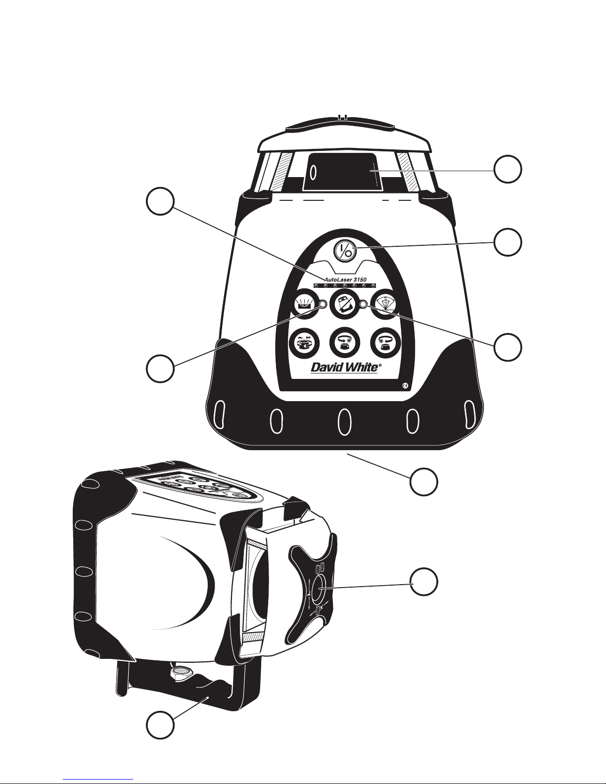
EN

1. Self-Leveling (+/-5º) Rotating
Laser Head. ( With vertical visible
split-beam 3150, 3175 only)
2. Battery Level LED Indicator Lights
When ALL lights illuminate,
instrument has full power. When
indicator lights reach Yellow it is time
to change/recharge batteries.
(3110-GR, 3150 only)
3. Anti-Drift System LED Indicator
(3110-GR, 3150 only)
4. Power ON/OFF button
5. Manual Mode LED Indicator
(3110-GR, 3150 only)
6. Manual Grade Adjustment Buttons
(3110-GR only)
7. 5/8” x 11 Tripod Mounting Threads (for
level work)
8. Gun Sight with “X” and “Y” Identifiers
9. Heavy-Duty Handle-(Built in Trivet for
Laydown and Vertical Applications
with 5/8” x 11 Thread 3150, 3175 only)
10. Select/Adjustment Buttons (3175 only)
11. LCD Display Panel (3175 only)
12. Mode Selection Button (3175 only)
3100 SERIES • 7
APPLICATIONS
Use your 3100 Series Self-Leveling Laser for these and many other projects:
Outdoor General Construction Applications & Site Preparation, Grading & Excavating, Batterboards
and Foundations, Masonry Work, Setting Concrete Forms, Machinery Installation, Marking
Elevation, Septic Work, Paving Roads, Driveways, Checking Depth of Trenches.
Drop Ceiling Installation, Floors, Cabinets & Shelves, Carpentry, Pools, Decks & Patios, Flagpoles,
Aligning 90° Joints & Edges, Landscaping, Tile Work, Septic Work, Plumbing, Batterboards,
Fencing, Walls & Partitions, Remodeling, Siding Installation, Doors & Windows.
Power Button (Allow 60
seconds for unit to self-level)
ADS Button– Anti-Drift System
ON | OFF (3110-GR, 3150 only)
Manual Mode/Automatic Level
Button (3110-GR, 3150 only)
Scanning Feature – 4 Preset
Angles ( 3150 only)
Variable Speed Rotation Button
– 4 Speed Selection (3150 only)
CW and CCW Button
Clockwise andCounter- Clock-
wise Head Positioning (Press
and Hold Button Moves the
Rotation More Quickly)
(3150 only)
Manual Grade Adjustment
Buttons (3110GR only)
ICONS
Reference in
the text
AA
BB
CC
DD
EE
FF
GG
HH
II
FEATURES - Fig. 1 , 2 & 3

8 • 3100 SERIES
Operating Instructions for General Construction Applications
NOTE: A level plane of laser light is created by the rotating beam of the laser. The laser light can be
used to reference elevations with the use of a laser detector. (Fig. 4)
1. Place the instrument on a flat, level surface such as a tripod. Setup the instrument in an
area where it can not be obstructed and is set at a convenient height.
2: Press the (A) button. Allow the instrument to self-level.
3. Setup a "Benchmark" .
4. 3150 and 3175 Only – Set the Variable Speed Rotation (page 10 ) to the desired rotation
speed of the laser head. Ideal speed for use with laser detector is 600 RPM.
5. Take elevation readings using the plane of laser light as a reference.Follow the Detector
Operation Procedures in this manual.
Ceiling Grid Applications
1. Attach the laser to the optional wallmount bracket. Be sure the control buttons are facing
outward. Tightening the locking screw will secure the instrument to the bracket.
2. After installing the first piece of ceiling trim, attach the wallmount to it. Be sure the
wallmount is secure to the trim.
3. Press the (A) button. Allow the instrument to self-level.
4. Adjust the distance of the instrument from the grid, typically 1.5-inch (38mm) below the grid.
Loosen the adjustment screw and slide the instrument up/down on the wall mount. When
the desired height has been reached, tighten the adjustment screw to secure the instrument.
NOTE: Setup a Benchmark
During the work day, periodically check your initial set-up to ensure that the laser reference
has not moved.
Establish, at a suitable distance (furthest possible), a benchmark (reference) on a stable surface
(ie. tree, building). Periodically during the work day, check the benchmark to ensure that your
setup has not moved.

5. Setup a "Benchmark" (page 8).
6. Install the ceiling grid. Attach the magnetic laser target to the ceiling trim being installed.
Adjust the height of the trim until the laser beam strikes the target.(Fig. 5)
Laydown Applications (3150, 3175)
1. Place the instrument in the laydown position on a flat, level surface.
2. Press the (A) button. Allow the instrument to self-level.(Fig. 6)
3. Setup a "Benchmark" (page 8).
OPERATION
Remove the laser from its carrying case. The instrument is shipped with a battery current
protection insert, which must be removed before operation.
NOTE: All 3100 Series instruments are shipped with ADS on as the default setting. This setting can
be changed by the user (see Anti-Drift System - ADS, page 12).
Note: 3175 instruments will default to Grade Mode when the instrument is turned on. The Mode
button is used for both selecting between the X-axis and Y-axis for setting grade and exiting the
Grade Mode (see Grade Mode — Dual or Single Axis Grade). Press and release the Mode button
to select between the X-axis and Y-axis when setting grade. To exit the Grade Mode, press and
hold the Mode button for 4 to 5 seconds, then release. This will bring up the Mode Select Menu.
The user can now toggle to other menu options. Pressing the Mode button for 4 to 5 seconds and
releasing is only required to exit the Grade Mode.
Leveling
1: The instrument can stand alone on a level, sturdy surface or preferably secured to a 5⁄8" x 11
surveyor’s tripod.
2: Press the (A) button once, and allow time (up to 60 seconds) for the instrument to self-level.
NOTE: The laser head may begin to rotate before leveling is complete. The self-leveling speed is
approximately 1° per 4 seconds.
3: After self-leveling, the instrument will begin operating in Rotation Mode. Note: The 3150 will
return to last mode of operation (i.e. sweep, spot, or rotation speed); however, does
not retain grade information.
NOTE: After self-leveling, the instrument will begin operating in Rotation Mode for 3110-GR, last
selected mode of operation (i.e. Sweep, Spot, Rotation Mode) for 3150, and Grade Mode for 3175.
Plumbing / Lay-Down (Models 3150 and 3175)
1. On a flat surface, place the instrument on its back using the built-in trivet (control panel
facing upward). (Fig. 7)
2. Press the (A) button once, and allow time for the instrument to self-level.
3100 SERIES • 9
Note: For fine adjustment of the vertical laser plane or of the 90° beam, please refer to “Line Position”
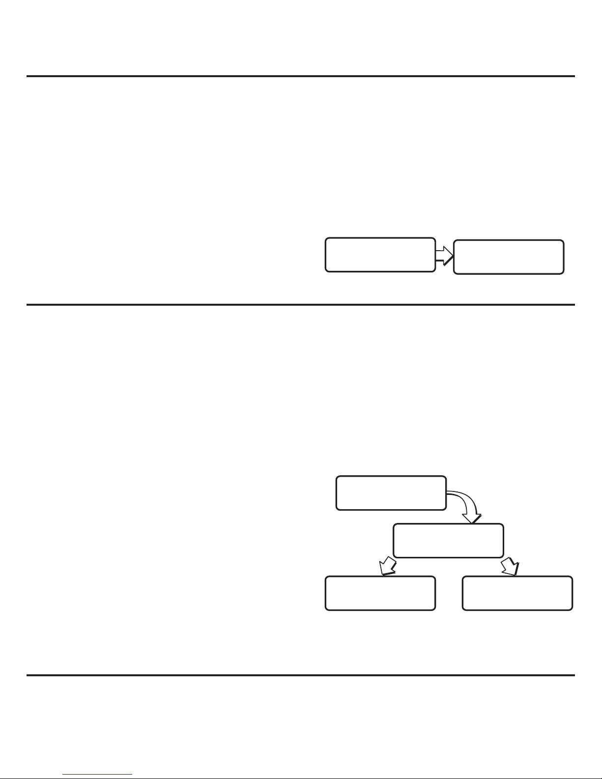
Variable Rotation Mode (Models 3150 and 3175)
The rotation mode will give you the option of increasing or decreasing the speed of the rotating
laser. This feature can be used to create a room-wide, 360° height reference or vertical plumb line
for general alignment, drop ceiling installation, and more.
model 3150
Pressing the (E) button, will adjust the speed from 600, 300, 150, and 0 RPM.
model 3175
Using the SELECT buttons, adjust the rotation speed in increments of 50 RPM; lowest possible
speed is 100 RPM and the highest is 1000 RPM.
Sweep or Scanning Mode (Models
3150 and 3175)
Instead of creating a room-wide reference line, the Sweep (Scanning) Mode creates a shorter,
brighter laser “chalk line” that can be used for leveling or plumbing doors, windows, fixtures, and
more. You may also use this feature to keep the instrument from interfering with other lasers and
detectors on site.
model 3150
Pressing the (D) button, will lengthen or shorten the sweep of the laser beam. Preset angles of 10º,
45º, 90º,180º and spot can be set. Position the sweep area by using the (F) or (G) buttons.
model 3175
Using the MODE button to enter the "POSition"
option, and use the SELECT buttons to position the
sweep clockwise or ccw. Press the MODE button to
return to SWEEP SETUP. Use the right SELECT button
to enter the “LENGTH” option and use the
corresponding SELECT buttons to lengthen or
shorten the sweep of the laser beam to the
appropriate length for your application. The sweep
can be as long as 359° or as short as 3°. The last
sweep setup entered remains in memory and will be recalled.
Point-to-Point Mode (Model 3175)
Similar to the Sweep Setup mode, the Point-To-Point Mode allows you to create a laser “chalk
line”, sweeping between any two positionsyou specify.
Use the left SELECT button to enter the “PTP: SET PT A” option, and use the SELECT buttons to
10 • 3100 SERIES
FAST SLOW
ROTATE 300
SELECT
ROTATION
SELECT
SWEEP SETUP
POS LENGTH
SWEEP SETUP
CCW CW
SWEEP POS
LONG SHORT
SWEEP LENGTH
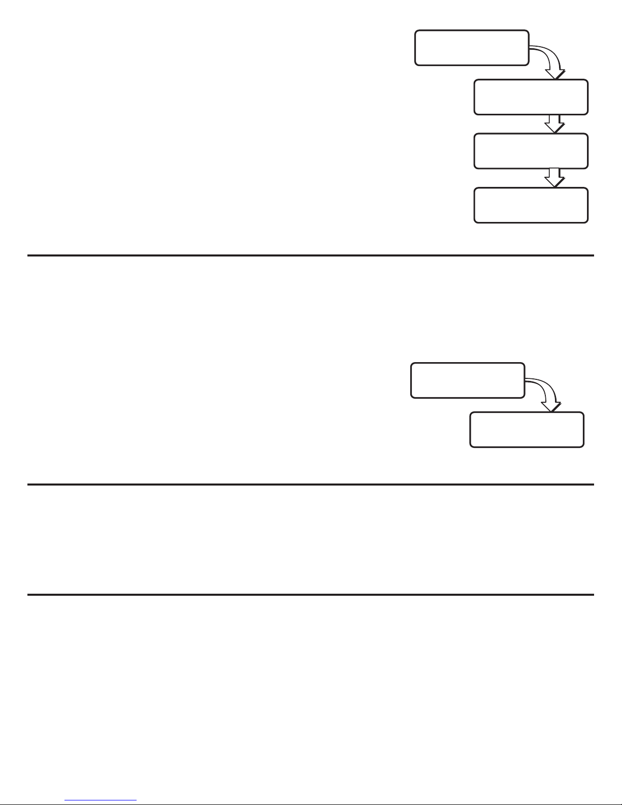
rotate the position of the start point clockwise or
counterclockwise. Press the MODE button to enter the “PTP: SET
PT B” option, and use the SELECT buttons to rotate the position of
the end point clockwise or counterclockwise. Press the MODE
button to begin the sweeping action between the two points. You
may use the SELECT buttons to readjust the position of each point
if needed.
NNoottee: In Sweep or Point-to-Point Mode, the selected sweep area
will not be exact. The laser will vary slightly from the
selected points.
Spot Mode (Models 3150 and 3175)
Spot Mode creates a motionless laser dot for reference, allowing the instrument to be used as a
straight-line laser.
model 3150
Press the (E) button untill the laser is in Spot Mode. Press the (F) or ( G) to rotate the laser head
clockwise or counter-clockwise. Pressing and holding the (G) or
(F) button moves the rotating beam more quickly.
model 3175
Use the SELECT buttons to rotate the position of the dot
clockwise or counterclockwise.
Re-Leveling (Models 3110-GR and 3150)
If the instrument is bumped or moved, the instrument will automatically attempt to re-level itself.
On a job site, it may be necessary to prevent re-leveling in order to prevent inaccurate
measurements by the operator. The Anti-Drift System (ADS) is used for this purpose (see Anti-Drift
System - ADS). The instrument can also be placed in Manual Mode to allow the instrument to
continue operating when out of level.
Axis Drive Error (Models 3110-GR and 3150)
If the laser is set up or tipped beyond its self-leveling range of ±5°, the laser head will initially
attempt to level; however, when the self-leveling limit is reached, an error will indicate an axis
error (Fig. 8).
Turn the instrument OFF, move the instrument to a more level position, then turn the instrument
on again.
Model 3175
The display shows “X TOO STEEP or Y TOO STEEP” Turn the instrument OFF, move the instrument
to a more level position, then turn the instrument on again.
If the instrument continues to poduce errors, contact David White®-Customer Service.
3100 SERIES • 11
SELECT
PT TO PT
CCW CW
PTP: SET PT A
CCW CW
PTP: SET PT B
PT A PT B
PTP: SWEEPING
SELECT
SPOT
CCW CW
SPOT

Spindle Motor Error
Models 3110-GR and 3150
If the laser spindle motor fails to rotate or rotates outside of the set speed, an error indicator will
indicate a spindle motor error (Fig. 8). If this occurs, see “Troubleshooting”.
Model 3175
The display shows “Spindle Motor Error”.
If the instrument continues to produce errors, contact David White®-Customer Service.
Auto Level Mode (Model 3175)
The Auto Level Mode allows you to control how the instrument
reacts when moved out of level.
Auto Level Mode can be ON, OFF, or ADS. If Auto Level Mode is
set to ON, the instrument will
re-level if the instrument is moved out of level.
If Auto Level Mode is set to OFF, the laser will NOT re-level if the
instrument is moved out of level, and will continue to operate; use
this option when using an adapter or mount that allows you to tilt
the instrument to create a diagonal laser line. Use the left SELECT
button to turn the Auto Level option ON or OFF. You may also put
the level into ADS Mode ( see Anti-Drift System- ADS).
Anti-Drift System – ADS (Models 3110-GR
3150, and 3175)
The Anti-Drift System, when ON, will signal to the operator that the instrument has been moved out
of level.The laser head will stop rotating, and the beam and ADS LED will blink in the models
3110GR and 3150; in the model 3175 the display will show “CONT UNIT UNLEVEL”.
Models 3150, 3110-GR
The default setting for ADS is user selectable. The default setting may be set to ADS ON or ADS
OFF. When the instrument is OFF, press and hold the “I” button (3110-GR) or the “G” button (3150)
and then press the “A” button. Once the instrument is on, turn the instrument off for 15 sec and
then back on. If ADS was ON (OFF), it will now be OFF (ON).
To activate ADS, turn off the Manual Mode (if it is ON), by pressing “C” and then press the ADS
(“B”) button. If after 1 minute, the instrument is disturbed and the ADS light is flashing it is
necessary to check any bench marks that have been made and ensure the proper "HI" (Height of
Instrument). After the flashing ADS has been reset, by pressing the button one time, you will have
an additional minute to set and check your measurements.
To turn ADS off press the “B” button once. This will put the instrument into normal Auto
Self-Leveling mode.
12 • 3100 SERIES
SELECT
AUTOLEVEL
ON
AUTOLEVEL
OFF
AUTOLEVEL
ADS
AUTOLEVEL

Model 3175
This function is prompted through the Auto Level Mode; it clearly
signals the user when the instrument is moved out of level. Turn ADS
on by selecting it in Auto Level Mode and using the MODE button to
return to your desired mode. If ADS is turned on, when the instrument
is moved out of level, the laser head will stop rotating and the beam will blink. The operator must
use the right SELECT button to select the “CONTinue” option.
The default setting for ADS is user selectable. When the instrument is OFF, press and hold the right
SELECT button and then press the ON/OFF button. Once the instrument is on, turn the instrument
off for 15 sec and then back on. This will toggle the default setting for Auto Level Mode between
ADS and on.
Grade Mode – Single Axis Grade (Models 3110-GR)
The single grade function is ideal for general site grading, checking excavations, landscaping and
drainage, and more. (Fig. 9)
The selected grade can be as much as a positive or negative 10%, and set in reference to the Y
axis of the instrument, noted by the embossed printing on the case.
Model 3110-GR
Manual grade mode can be activated by placing the automatic leveling sensor in the OFF position.
NOTE: The ADS must be deactivated to use the Manual Select button.
Pressing the “C” button will deactivate the level sensor. Using the “H” ("MORE") and “I” ("LESS")
arrow buttons, adjust to your desired grade. Rotating head tilts on the Y axis.
NOTE: If the instrument is bumped or moved while in Manual Grade mode, the instrument will not
re-level itself.
The laser will react to “MORE” and “LESS” input. Allow the instrument ample time to react to the
input provided, between grade setups or changes. (Fig. 10)
Manual Grade Mode (Models 3150, 3110-GR and 3175)
Manual mode disengages the leveling feature, allowing the instrument to be placed in any position
to grade.
To activate the Manual Mode, Turn off the ADS (if it is on) and then press the “C” button. (Note:
The instrument should be level and rotating before entering manual mode to eliminate the
possibility of error.) Once the button has been pressed the Manual Mode Indicator Light will blink.
Press the “C” button again to return to normal operation.
Note: When returning to normal operation the instrument must be within its leveling range. Re-set
the instrument to a level position before pressing the “C” button to the off position.
NOTE: (Model 3150) Once the instrument is in manual mode, the remote can be used to set a slope
in the Y-axis by pressign the UP or DOWN button, or X-axis by pressing the remote LEFT or RIGHT
Arrow Button.
3100 SERIES • 13
CONT
UNIT UNLEVEL
Grade Mode – Dual or Single Axis Grade (Model 3175)
The dual grade function allows more specialized site preparations such as road grading, airport
jobs (grading & paving), irrigation, trenching, landfills, slopes and
embankments, and pipelaying. (Fig.11)
The Dual Grade Mode screen is the default screen when the instrument
is turned on. Use the MODE button to choose either the X axis or Y axis.
An > on the display will indicate the selected axis. Press the left SELECT
button to increase slope, press the right SELECT button to decrease slope. Ideally for single axis
grade, use the Y axis in order to use the top mounted sight to orient the instrument to your target,
as well as locate the high and low positionswithin the arc. While grade on both axes is set to zero,
the instrument will continue to self-level. Percentage of grade can be selected at any time while in
this mode. However, the instrument will not go to the desired grade until the instrument has
leveled.
Allow the instrument ample time to react to the input provided. Refer to examples in (Fig. 12) to
predict your results.
To exit Grade Mode, press and hold the MODE button for 4 to 5 seconds. When the button is
released, the MODE select menu is available. (it is not necessary to press and hold the MODE
button to exit any other mode).
NOTE: The total percent grade possible is from a perfectly level base position. If the instrument is
mounted on a tripod head which is not perfectly level, then the grade percentage range capability
would be reduced by the slope of the base, as this affects the tilt range of the laser head. For
maximum grade range, ensure a level tripod head using a spirit level before mounting
your instrument.
FOR ALL GRADE LASERS: For greater accuracy in grade applications, precisely level the laser
level before entering into GRADE MODE.
FOR 3175: If the instrument can’t achieve desired grade it will give an error message “GRADE TOO STEEP”
Anti-Drift in Grade Mode (Models 3175)
The Auto Level Mode can be set to ADS while instrument is in
Grade Mode. ADS will protect against accidental bumps or
settling of the instrument that could cause errors. If the
instrument has been setup to default to Auto Level ADS at startup,
the Grade Mode ADS is already on. If the instrument has not been
set up to default to Auto Level ADS at startup, enter the Auto
Level Mode and selecting ADS. Return to Grade Mode after
selecting ADS. ADS will only be active as long as one axis is set
to zero percent grade (Single Axis Grade). ADS will not be active
while in Dual Axis Grade. ADS is automatically disabled for 30
seconds whenever a new set point is entered for the grade axis.
In Grade Mode, when the instrument is moved out of grade level,
the laser head will stop rotation and the beam will blink to indicate to
the operator that the HI of the instrument may have changed. To
continue, the operator must acknowledge by pressing the right
SELECT button to select the “CONTinue” option.
14 • 3100 SERIES
SELECT
AUTOLEVEL
ON LEVEL
AUTOLEVEL
OFF LEVEL
AUTOLEVEL
ADS LEVEL
AUTOLEVEL
CONT
UNIT UNLEVEL
+ >X 0.00% –
>Y 0.00% –

NOTE: If movement occurs in only the grade axis, ADS may not indicate movement since the
movement is being detected by the non-grade (level) axis. However, in a real world application,
both the grade and level axis will likely move.
Line Position Mode (Model 3150 and 3175)
In this mode, the instrument allows you to fine-tune the location of your vertical (plumb) laser line.
For example, if you’ve established a plumb line and find that the line is slightly off to the left or right
of your target, use Line Position to jog the line into place without moving the entire instrument
(useful for floor and wall tile installation, walls or partitions, etc.). The laser will now remain aligned
to your target even if you enter other modes (Rotation, Spot, Point-to-Point)
model 3150
Line Position mode is available when the instrument is placed in the plumbing position (control
panel facing upward). While the instrument is in the plumbing position, it can be used in Rotation,
Sweep or Spot mode. To enter the Line Position mode and position the laser reference point the
instrument must be rotating. Use the “F” or “G” buttons to position the laser reference point while
the instrument is rotating ( Fig. 13). If the instrument is in Spot or Sweeping mode the “F” and “G”
buttons are used to move the spot or sweep clockwise and counterclockwise, as they do when
the laser is in the upright position.
NOTE: The LEFT and RIGHT buttons of the RC700 Remote can be used to position the reference line
regardless of the instrument being in Rotation, Spot, or Sweep Mode.
If in manual mode , the LEFT and RIGHT buttons will position the reference line and the UP and
DOWN buttons will move the vertical line up and down
model 3175
Line Position mode is available when your instrument is placed in the
plumbing position (control panel facing upward). While the instrument
is in the pluming position, it can be used in Rotation, Spot, or Point-to-
Point mode. To enter Line Position mode, use the Mode button to go to
the Line Position option and press select. The instrument will rotate at
the last rotation speed selected. Press the SELECT buttons to move the position of the laser
reference point clockwise (right) or counterclockwise (left) into perfect alignment with your target.
(Fig.14)
REPLACING BATTERY
For models 3110-GR and 3150, if the battery is low, the red light (only) is illuminating on the front of
the instrument.
For model 3175, if the battery is low, the LCD will display “ERROR BATTERY LOW”.
If the instrument operates erratically, try replacing the batteries. (Fig.15)
1. Remove the battery tray by unscrewing the plastic nut around the mounting thread
on the bottom of the instrument.
2. Remove the old batteries and replace with 4 new “D” cell Alkaline batteries.
3100 SERIES • 15
CCW CW
LINE POS

3. Replace the battery tray. Make sure the battery contacts between the battery pack
and the instrument compartment are aligned.
NOTE: Do not mix old and new batteries. Replace all batteries at the same time with new batteries.
Remove batteries before storage of the instrument.
Rechargeable Battery Pack
If you are using a rechargeable battery pack (Cat #57-NB700), your instrument will provide
approximately 14 hours of intermittent use with each full charge. The batteries will begin to
perform optimally after five full charges and discharges. You may charge the battery pack within
the instrument.
Ensure the power is off, and connect the charging plug to the appropriate charging jack on the
bottom of the battery pack. Then plug the charger into the appropriate 120/230V AC outlet. Charge
time is typically around 8 hours . The instrument can be charged and used at the same time, but
only a minimal charge will be applied to the battery pack.
CALIBRATION
Your 3100 Series Self-Leveling Laser is a sealed instrument and is calibrated to precise accuracies
at the factory. However, a calibration check is recommended before the initial use of your laser,
and then periodically from that point forward. Be sure to allow time (up to 60 seconds) for the
instrument to completely self-level before each check.
Upright Position Peg Test – X axis (All models)
1. To test the X axis, mount the laser on a tripod or a level, sturdy surface and place
100 feet (30m) away from a wall. Face the “X+” side of the instrument to the wall (Fig. 16).
2. Press the “A” button and allow the instrument to self-level. Using the laser detector, locate
and mark the position of the laser line on the wall Position “A”).
3. Loosen the instrument from the tripod and rotate the instrument 180°. Ensure that the height
of the tripod does not change, as this will affect your results. Secure and re-level
the instrument.
4. Again, using the laser detector, locate and mark the position of the laser on the
wall (Position “B”).
5. Mark the centerline between Position A and Position B (Position C). Callibration is necessary
if the vertical difference between Position A and Position C or Position B and Position C is
greater than the specified accuracy.
Repeat the above steps to ensure a correct reading. If the distance is greater than specified
accuracy, you will need to calibrate the X axis.
NOTE: For 3150 and 3175 Spot Mode can be used without detector if designed
16 • 3100 SERIES

Upright Position Calibration– X axis
model 3110-GR (Fig.16)
1. Power On the instrument with the “A” button while holding the “C” button down, then
release the “A” button. You will know if Calibration Mode is activated when the Manual
Mode and Anti-Drift LEDs flash alternately. Then, the Manual Mode LED will remain lit; this
indicates that the instrument is calibrating within the X axis.(Fig. 17)
2. The “H”and “I” buttons change the axis increments. The ”H” button will produce a
positive (+) increment.
NOTE: for 3110-GR Pressing the “C” button will toggle between Xand Y axis for calibration. Manual
LED on indicates X- axis is selected.
3. You must raise or lower the beam to center between positions A and B (position C) on the
target. The instrument will react to “+” and “–” input within the X+ quadrant. The instrument
DOES NOT react to adjustments until the instrument is forced to re-level (i.e. rotate
and re-check point A).
If B is below A, increase the increment (+).
If B is above A, decrease the increment (-).
4. The adjustments are automatically saved.
You must now repeat the peg test to insure you have made the correct calibration. A peg test can
be done in Calibration Mode.
model 3150
1. Power On the instrument while holding the “C” button. You will know if Calibration Mode is
activated when the Manual Mode and Anti-Drift LEDs flash alternately.
2. The “C” and “E” button change the X-axis increments. The “C” button will produce a
positive (+) increment (the “D” and “F” will change the Y-axis. And the “D” button will
produce a positive (+) for Y). (Fig.17)
3. You must raise or lower the beam to center between positions A and B on the target. The
instrument will react to “+” and “–” input within the X+ quadrant. The instrument DOES NOT
react to adjustments until the instrument is forced to re-level (i.e. rotate and re-check point A).
If B is below A, increase the increment (+).
If B is above A, decrease the increment (-).
4. The adjustments are automatically saved.
You must now repeat the peg test to insure you have made the correct calibration. A peg test can
be done in Calibration Mode.
3100 SERIES • 17

model 3175
1. Power ON the instrument while holding the MODE button down.
2. Release both buttons at the same time and wait for calibration instructions to appear on
screen. You will have to select the direction of calibration change.
3. Use the right SELECT button, following the chart, to access the X axis for calibration .
Please record the three-digit number that appears in the LCD the first time you enter the axis
calibration menu; this number is the factory setting (i.e. 510), to which you can return if
necessary (this number may vary anywhere between 430 and 590).
You must raise or lower the beam to center between positions A and B(Position C) on the wall. The
instrument will react to “+” and “–” input within the X+ quadrant.
If B is below A, increase the number (”+”).
If B is above A, decrease the number (“–”).
4. Press the MODE Button to exit the X axis calibration menu, and save any changes to the
calibration settings by turning off the instrument (“QUIT”).
You must now repeat the peg test to insure you have made the correct calibration. A peg test can
be done in Calibration Mode.
Upright Position Peg Test and Calibration – Y axis (All models)
To test the Y axis, mount the instrument on a tripod and place approximately 100 feet (30m) away
from the target, with the control side (Y+ quadrant) facing the target (Fig. 18); follow steps 2 thru 4
of "Upright Position Peg Test – X axis". Calibrate as in "Upright Position Calibration – X axis",
choosing the Y axis to calibrate and adjusting “+” and “–” input as necessary within
the Y+ quadrant.
Note: In the model 3110-GR, in order to calibrate the Y axis, when the Manual and ADS LED’s flash
to indicate that you entered the Calibration Mode, press the Manual button in order to turn off the
corresponding LED.
If you are unable to calibrate the instrument, or if the difference between positions A and B is too
great to calibrate within the numerical range of 430 to 590, please contact David White or an
authorized service center for assistance.
Laydown Position Peg Test – Z axis (3150, 3175 only)
1. To test the Z axis, place the instrument on its back using the built-in trivet (control panel
facing upward), 100 feet (30m) from a wall on a flat, level surface.
2. Hang a plumb line down the wall at least 8 feet long (2,5 m).
18 • 3100 SERIES
LANG CAL
QUIT
X Y Z
BACK
CAL POS
BACK
X Y
BACK
SPOT ROTATE
QUIT
X Y
Z QUIT
CCW CW
BACK
+ Y AXIS -
BACK 510
+ X AXIS -
BACK 510
+ Z AXIS -
BACK 510

3. Press the “A” button (“POWER” in the 3175) and allow the instrument to self-level. If
necessary, adjust the rotation speed to easily view the laser beam on the wall. Orient the
instrument parallel to the wall and attempt to align with your plumb line. (Fig.19)
If the laser line does not align with the plumb line, then calibration is necessary.
Laydown Position Calibration – Z axis (3150 and 3175 only)
Keep the instrument in its current position. Power OFF the instrument.
model 3150
1. Power ON the instrument while holding the “C” button down. You will know if Calibration
Mode is activated when the Manual Mode and Anti-Drift LEDs flash alternately.
2. The “D” and “F” button change the axis increments. The “D” button will produce a
positive (+) increment.
3. Select the “D” button to rotate the laser beam counterclockwise, or the “F” button to rotate
the laser beam clockwise into alignment with your plumb line.(Fig. 19) For example, the beam
must rotate counterclockwise to align with the plumb line, so you must select the “D” button.
4. The adjustments are automatically saved.
model 3175
1. Power ON the instrument while holding the MODE button down.
2. Release the two buttons at the same time and wait until calibration instructions appear on
screen. Use the right SELECT button, following the chart You find in “Calibration of the X
axis”. To access the Z axis press MODE. Please record the three-digit number that appears
in the LCD the first time you enter the axis calibration menu; this number is the factory
setting (i.e. 510), to which you can return if necessary (this number may vary anywhere
between 430 and 590).
3. Select “+” to rotate the laser beam counterclockwise, or “–” to rotate the laser beam
clockwise into alignment with your plumb line. For example, the beam must rotate
counterclockwise to align with the plumb line, so you must select “+”.
4. Press the MODE Button to exit the Z axis calibration menu, and save any changes to the
calibration settings by turning off the instrument (“QUIT”).
You must now repeat the peg test to insure you have made the correct calibration. A peg test can
be done in Calibration Mode.
MAINTENANCE AND CARE
Always clean the instrument after use. Use a soft, dry cloth to remove any dirt or moisture from the
instrument. Do not use benzene, paint thinner, or other solvents to clean the instrument. Store the
instrument in its case when not in use. Batteries should be removed before long-term storage.
ENVIRONMENTAL PROTECTION
Recycle raw materials instead of disposing as waste. The machine, accessories and
packaging should be sorted for environmental-friendly recycling. Do not throw used
batteries into waste, fire or water but dispose of in an environmentally friendly manner
according to the applicable legal regulations.
3100 SERIES • 19

SPECIFICATIONS
TROUBLESHOOTING
The following information lists basic tests that can be performed to check the 3100 Series in the
event of poor performance.
Check Your Batteries: One of the most common causes of performance failures is due to defective
or incorrectly installed batteries. Check to see if any batteries are installed backwards and correct
if necessary.
20 • 3100 SERIES
Weight
Laser Only
Beam Type
class II/IIIa
Operating Range
with Laser Detector
Leveling Type
Horizontal Leveling
Vertical Leveling
Grade Capability
Manual
Up to 2000-feet (610m) Diameter with Laser Detector
Electronic Self-Leveling
Leveling Accuracy
Vertical Accuracy
±1/16-inch@100’ ±1/8-inch@100’ ±1/16-inch@100’
8" Height x 6-1/4" Width x 6-3/8" Depth
(203mm H x 159mm W x 162mm D)
75± Hours Intermittent Use with Alkaline Batteries
14+ Hours Used with Fully Charged Ni-Cad Battery Pack
650 nm
3110-GR 3150 3175
635 nm
"hi-powered" 635 nm
"hi-powered"
Dimensions
Yes Yes Yes
No Yes Yes
Single Axis
Up to ±10%
Single Axis
Up to ±10%
w/Remote
Dual Axis
Up to ±10%
Visible Split-Beam No Yes Yes
Self-Leveling Range ±5º ±5º ±5º
Grade Accuracy ±0.1% Grade
––––
––
Rotation Speed
600 0, 150, 300, 600 0 - 1000
RPM
Battery Power
5.5 ± lbs. (2.5kg) with Batteries
Scanning Feature No Yes Yes
Operating Temperature -4º F to 120ºF
(-20ºC to 49ºC)
Environment IP54 - Water Resistant
VariableFixed
with
"ADS"
(±1.5mm at 30m) (±1.5mm at 30m)(±3mm at 30m)
±1/8-inch@100’
(±3mm at 30m)
±1/8-inch@100’
(±3mm at 30m)
Other manuals for AutoLaser 3110-GR
1
This manual suits for next models
2
Table of contents
Languages:
Other David White Measuring Instrument manuals


