DAVID HI-CAP 548 User manual
548
GRAIN
CLEANER
OWNERS
MANUAL
AND
.
PARTS
LIST
DAVID
MANUFACTURING COMPANY
Ma$on
City,
Iowa
50401
\

(RIGHT
SIDE)
MODEL
"548 HI-CAP GRAIN
CLEANER
,l~./
,
C;
''':'';' (
(LEfT SIDE)
0079
INTRODUCTION
Congratulations
I
You
made
a
very
wise
decision
in
purchasing
a
Model
548
Hi-Cap
Grain
Cleaner,
and
with
the
wide
range
of
screen
sizes
which
are
available,
it
will
take
care
of
all
your
screening
needs.
With
its
dual
screening
action,
it
not
only
removes
"fines",
chaff,
etc.,
but
also
the
large
trash
such
as
cob
particles,
straw
and
stalks.
If
equipped
with
an
eight
inch
feed-in
auger,
it
will
operate
in
a
full
half-circle
for
ease
unlopding
of
grain.
With
proper
maintenance,
your
new
Model
548
Hi-Cap
Grain
Cleaner
will
give
you
years
of
reliable
service.
SERVICE
Lubricate
all
grease
fittings
every
500
bushels,
or
at
least
once
every
year.
At
the
same
time,
check
belt
tensions
and
clean
any
accumulated
trash
out
of
the
pulley
grooves.
~~~~~~~~~~~~~~~
FOR
YOUR
PROTECTION
"..~'
~
~
KEEP
ALL
SAFETY
SHIELDS
IN
PLACE!
".
~
~
.~~~~~~~~~,.,~~
.~
As
with
all
moving
machinery,
DO
NOT
stand
close
to
the
Hi-Cap
Grain
Cleaner
while
it
is
operating,
and
always
stop
it
to
make
adjustments.
OPERATION
The
cleaning
drum
should
turn
21
revolutions
per
minute,
and
rotate
clockwise
when
viewed
from
the
feed-in
end.
The
cleaner
should
be
run
until
empty
before
stopping.
It
is
not
advisable
to
leave
grain
in
the
cleaner
or
start
the
cleaner
with
a
load
of
grain
in
it.
The
ADJUSTABLE BAFFLE
in
the
internal
screen
serves
two
purposes:
first,
to
force
the
grain
through
the
coarse
screen
close
to
the
feed-in
end,
to
insure
as
much
fine
screening
as
possible,
and
secondly
to
prevent
grain
from
working
to
the
far
end
and
out
through
the
large
particle
chute.
It
will
be
found
that
the
baffle
can
be
closer
to
the
feed-in
auger
for
dry
grain
than
for
wet.
Observation
of
operation
will
reveal
the
need
for
adjustment
to
give
most
efficient
cleaning.
If
the
grain
tends
to
build
up
in
the
internal
screen,
set
the
baffle
plate
farther
toward
the
large
particle
chute
end.
Otherwise,
keep
it
as
close
to
the
feed-in
end
as
possible.
The
ADJUSTABLE JACK-STAND
provides
two
functions:
1)
it
enables
you
to
hook
the
Model
548
up
to
your
prime
mover
very
easily,
and
2)
it
also
serves
as
the
leveling
jack
when
the
Hi-Cap
is
in
working
position.
A
decal
arrow
placed
near
the
leveling
jack
permits
you
to
adjust
the
slant
of
your
Model
548
to
fit
your
cleaning
needs.
(See
Photo
12).
The
grain
will
pass
through
the
cleaner
faster
with
a
steep
slant;
the
cleaning
action
,will
be
more
thorough
with
less
slan~.
U
t\-7
1-
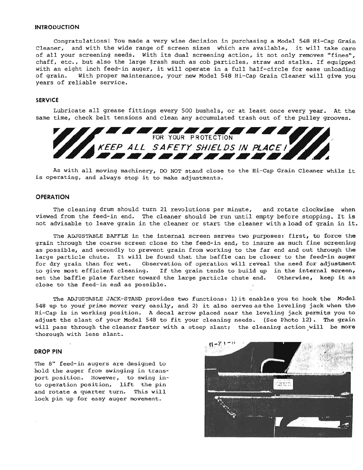
DROP
PIN
The
8"
feed-in
augers
are
designed
to
hold
the
auger
from
swinging
in
trans-
port
position.
aowever,
to
swing
in-
to
operation
position,
lift
the
pin
and
rotate
a
quarter
turn.
This
will
lock
pin
up
for
easy
auger
movement.

2
SCREENS
A
variety
of
screens
can
be
obtained
to fit
your
needs.
When
viewing
the
grain
cleaner
from
the
grain
discharge
end,
the
outside
screens
should
be
put
on
so
that
the
lap
is as
shown
in
the
drawing:
Lap
If
screens
are
not
properly
placed
on
the
screener,
grain
can
get
in
behind
the
lap
and
cause
problems.
The
lap
should
also
be
over
the
tumbling
bars.
Ma ke
sure
that
a
II
of
the
slack
is
taken
out
of
the
screen
before
the
bands
are
attached.
This
can
be
done
quite
easily
with
the
help
of
a
couple
common
door
springs.
Hook
the
springs
on
to
the
screen,
making
sure
the
lap
is
on
the
proper
side,
then
tap
the
screen
Ii
~
Drum
Rotation
ghtly.
This will
remove
all
the
slack. Last,
the
outside
screen
straps
are
put
over
the
screen.
To
have
the
straps
positioned
correctly,
the
bolts
that
tighten
the
straps
should
come
directly
over
the
screen
lap. Eight
straps
are
required;
four
per
screen
section.
Screen
straps
positioned
over
drum
rings
need
to
be
tightened
very
securely.
Straps
that
encompass
drum
over
tumbling
b<HS
require
care in
tightening
so
that
the
tumbling
bars
are
not
compressed.
TIRE
PRESSURE
20
PSI
will
give
your
tires
maximum
tire life
and
yet
provide
floatation
for
your
Hi-Cap
while
being
towed
at
highway
speeds.
TOWING
SPEED
Towing
~peed
should
not
exceed
50
miles
per
hour. For
highway
use,
connect
safety
chain.
OPTIONAL EQUIPMENT:
8"
x
11"
auger
with
Hopper and Slide Gate
Collector
pan
Stationary model
1
Y2
HP
Auger
Motor
Screens
to match
your
operation
ALL
HI-CAP
MODEL
548
GRAIN
CLEANER
MOTORS
ARE
WIRED
230
VOLTS
3
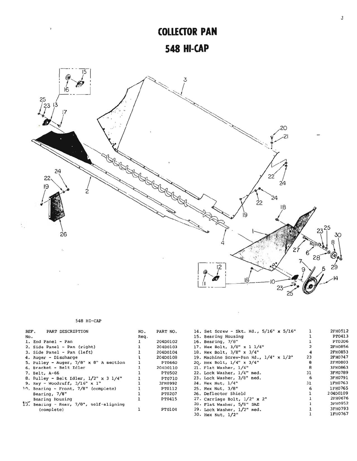
COLLEaOR
PAN
548
HI-CAP
548
HI-CAP
REF.
PART
DESCRIPTION
NO.
PART
NO.
14.
Set
Screw
-
Skt.
Hd. ,
5/16"
x
5/16"
1
2FH05l2
No.
Req.
15.
Bearing
Housing
1 PTQ413
l-
End
Panel
-
Pan
1
20400102
16.
Bearing,
7/8"
1 PT0206
2.
Side
Panel
-
Pan
(right)
1
20400103
17.
Hex
Bolt,
3/8"
x 1
1/4"
2 2FH0856
3.
Side
Panel
-
Pan
(left)
1
20400104
18.
Hex
Bolt,
3/8"
x
3/4"
4 2FH0853
4.
Auger
-
Discharge
5.
Pulley
-
Auger,
7/8"
)(
au
A
section
1
1
20400108
PT0660
19.
20•.
Machine
Screw-Pan
Hd.,
Hex
Bolt,
1/4"
x
3/4"
1/4"
x 1/2·" 23
8 2FH0747
2FH0803
6.
Bracket
-
Belt
Idler
1
20400110
21.
Flat
Washer,
1/4"
8 3FH0863
7.
Belt,
A-66
1 PTOS02
22.
Lock
Washer,
1/4"
med.
31
3FH0789
8.
Pulley
-
Bel
t
Idler,
1/2"
x 3
1/4"
1 PT0710
23.
Lock
Washer,
3/8"
med. 6 JFH0791
9.
Key -
Woodruff,
J/16"
H'
BQaring
-
Front,
7/8"
x
1"
(complete)
1
1 3FH0992
PT01l2
24.
25.
Hex
Nut,
Hex
Nut,
1/4"
3/8"
31
6 lFH0763
lFH0765
t3~
Bearing,
7/8"
Bear
ing
Housing
Bearing
-
Rear,
(complete)
7/8",
self-aligning
1
1
1
PT0207
PT0415
PT0104
26.
27.
2G.
29.
30.
Deflector
Shield
Carriage
Bolt,
1/2"
x 2
11
Flat
Washer,
5/8"
SkE
LOck
Washer,
1/2"
med.
Hex
Nut,
1/2"
1
1
I
1
1
20400109
2Ffl0676
Jf'H0952
3FH0793
IFIl0767
4
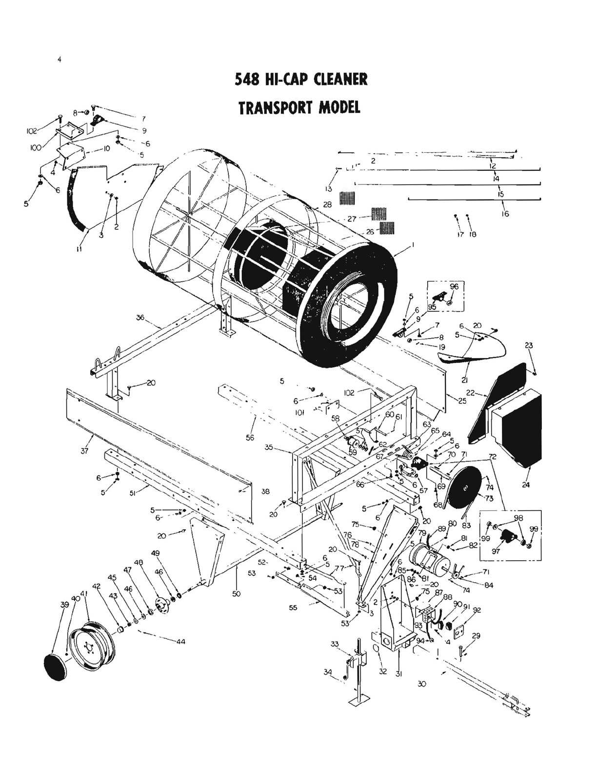
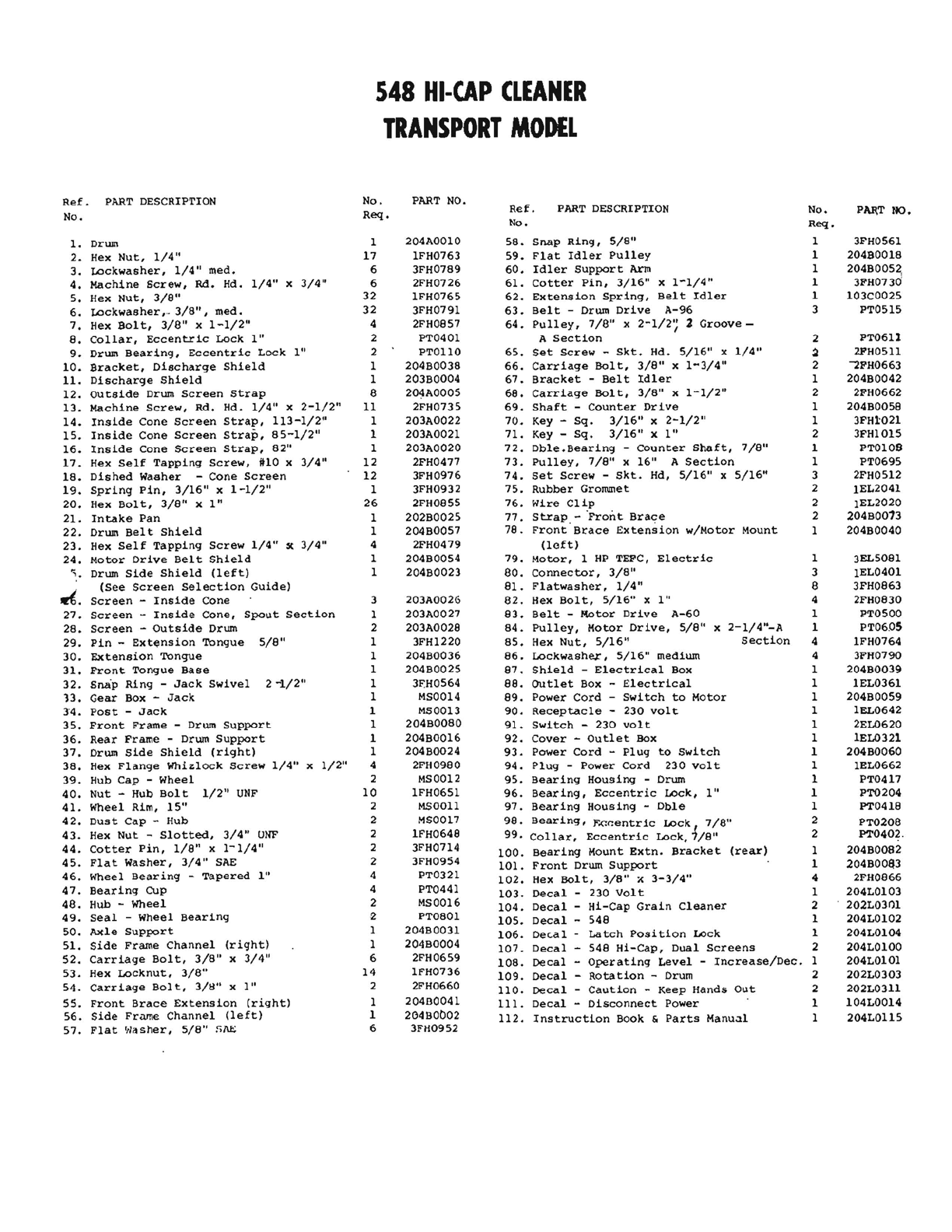
548
HI-CAP
CLEANER
TRANSPORT
MODEL
\\
17
18
548
HI-CAP
CLEANER
TRANSPORT
MODEL
Ref.
PART
DESCRIPTION
No.
PART
NO.
Ref.
PART DESCRIPTION
No.
PAR,T
NO,
No.
Req.
No.
Req.
1.
Drum 1204AOOIO
58.
Snap
Ring,
5/8"
2.
Hex
Nut,
1/4"
17
IFH0763
59.
Flat
Idler
Pulley
3.
Lockwasher,
1/4"
med.
6
3FH0789
60.
Idler
Support
Arm
4.
Machine
Screw,
Rd.
Hd.
1/4"
x
3/4"
6
2FH0726
61.
Cotter
Pin,
3/16"
x
1-1/4"
5.
Hex
Nut,
3/8"
32
IFH0765
62.
Extension
Spring,
Belt
Idler
3FH0561
204B0018
1
1
1
1
1
204B005~
3FH0730
103C0025
6.
Lockwasher,.,
3/8",
med.
32
3FH0791
63.
Belt
-Drum
Drive
A-96
3
PTOSIS
7.
Hex
Bolt,
3/8"
x
1-1/2"
4
2FH0857
64.
Pulley,
7/8"
x
2-1/2';
2
Groove-
PT0401
A
Section
2
PT0611
PTOllO
65.
Set
Screw
-
Skt.
Hd.
5/16"
x
1/4"
~
21'H0511
8.
Collar,
Eccentric
Lock
1"
9.
Drum
Bearing,
Eccentric
Lock
1"
10.
Bracket,
Discharge
Shield
11.
Discharge
Shield
2
2
1
1
"""2FH0663
204B0042
2FH0662
204B0058
3FH3:021
3FHI015
2
1
2
1
1
2
204B0038
66.
Carriage
Bolt,
3/8"
x
1-3/4"
203B0004
67.
Bracket
-
Belt
Idler
Carriage
Bolt,
3/8"
x
1-1/2"
12.
Outside
Drum
Screen
Strap
8
204A0005
68.
13.
Machine
Screw,
Rd.
Hd.
1/4"
x
2-1/2"
11
2FH0735
69.
Shaft
-
Counter
Drive
203A0022
70.
Key
-
Sq.
3/16"
x
2-1/2"
203A0021
71.
Key
-
Sq.
3/16"
xl"
14.
Inside
Cone
Screen
Strap,
113-1/2"
15.
Inside
Cone
Screen
Strap,
85-1/2"
16.
Inside
Cone
Screen
Strap,
82"
1
1
1
203A0020
72.
Dble,Bearing
-
Counter
Shaft,
7/8"
PTOI08
PT0695
1
1
2FH0477
73.
Pulley,
7/8"
x
16"
A
Section
17.
Hex
Self
Tapping
Screw,
1110
x
3/4"
12
18.
Dished
Washer
-
Cone
Screen
12
3FH0976
74.
Set
Screw
-
Skt.
Hd,
5/16"
x
5/16"
3
2FH0512
2
lEL2041
3FH0932
75.
Rubber
Grommet
1
19.
Spring
Pin,
3/16"
x
1-1/2"
2FH0855
76.
Wire
Clip
lEL2020
204B0013
26
2
2
20.
Hex
Bolt,
3/8"
x
1"
202B0025
77.
Strap.
-
'Front
Brace
1
1
21.
Intake
Pan
22.
Drum
Belt
Shield
204B0057
78.
Front
Brace
Extension
w/Motor
Mount
204B0040
1
23.
Hex
Self
Tapping
Screw
1/4"
'C
3/4"
4
2FH0479
(left)
24.
Motor
Drive
Belt
Shield
'.
Drum
Side
Shield
(left)
1
1
204B0054
79.
Motor,
1
HP
TEFC,
Electric
1
3EL5081
204B0023
80.
Connector,
3/8"
3
lEL040l
(See
Screen
Selection
Guide)
8l.
Flatwasher,
1/4"
8
3FH0863
~.
Screen
Inside
Cone
3
203A0026
82.
Hex
Bolt,
5/16"
xl"
4
2FH0830
27.
Screen
-
Inside
Cone,
Spout
Section
1
203A0027
83.
Bel
t -
Rotor
Drive
A-60
1
PT0500
28.
Screen
-
Outside
Drum
29.
Pin
-
Extension
Tongue
5/8"
30.
Extension
Tongue
31.
Front
Tongue
Base
32.
Snap
Ring
-
Jack
Swivel
2
-1/2"
13.
Gear
Box
-
Jack
34.
Post
-
Jack
35.
Front
Frame
-
Drum
Support
36.
Rear
Frame
-Drum
Support
37.
Drum
Side
Shield
(right)
2
1
1
1
1
1
1
1
1
1
203A0028
84.
pulley,
Motor
Drive,
5/8"
x
2-1/4"-A
1 PT06.0S
3FHl220
85.
Hex
Nut,
5/16"
Section
4
lFH0764
204B0036
86.
Lockwasher,
5/16"
medium
4
3FH0790
204B0025
87.
Shield
-
Electrical
Box
1
204B0039
3FH0564
88.
OUtlet
Box -
Electrical
1
lEL0361
MS0014
89.
Power
Cord
-
Switch
to
Motor
1
204B0059
MS0013
90.
Receptacle
-
230
volt
1
lEL0642
204B0080
91.
Switch
-
230
volt
1
2EL0620
204B0016
92.
Cover
-
Outlet
Box
1
lEL0321
204B0024
93.
Power
Cord
-
Plug
to
Switch
1
204B0060
38.
Hex
Flange
Whizlock
Screw
1/4"
x
1/2"
4
2FH0980
94.
Plug
-
Power
Cord
230
volt
1
lEL0662
39.
Hub
Cap
-
Wheel
2 MS0012
95.
Bearing
Housing
-Drum 1
PT04l7
40.
Nut
-
Hub
Bolt
1/2"
UNF
10
IFH0651
96.
Bearing,
Eccentric
Lock,
1"
1
PT0204
41.
Wheel
Rim,
15"
2 MSOOll
97.
Bearing
Housing
-
Dble
1
PT0418
42.
Dust
Cap
-
Hub
2MS0017
98.
Bearing,
F.Gl":entric
Lock
7/8"
2
PT0208
43.
Hex
Nut
-
Slotted,
3/4"
UNF 2
IFH0648
99.
Collar,
Eccentric
Lock,1/8"
2
PT0402.
44.
Cotter
Pin,
1/8"
x
1-1/4"
2
3FH0714
100.
Bearing
Mount
Extn.
Bracket
(rear)
1
204B0082
45.
Flat
Washer,
3/4"
S1\E
2
3FH0954
101.
Front
Drum
Support
1 204BOO&3
46.
Wheel
Bearing
-
Tapered
1"
4
PT0321
102.
Hex
Bolt,
3/8"
J(
3-3/4"
4
2FH0866
PT0441
47.
Bearing
Cup
48.
Hub -
Wheel
49.
Seal
-
Wheel
Bearing
50.
Axle
Support
51.
Side
Frame
Channel
(right)
4
2
2
1
1
103.
Decal
-
230
Volt
1
204LOl03
MS0016
104.
Decal
-
Hi-Cap
Grain
Cleaner
2
202L03r:ll
PT0801
105.
Decal
-
548
1
204LOl02
204B0031
106.
Dec.a1 -
La
tch
Position
Lock
1
204LOl04
204B0004
107.
Decal
-
548
Hi-Cap,
Dual
Screens
2 204LOlOO
52.
Carriage
Bolt,
3/8"
x
3/4"
6
2FH0659
108.
Decal
-
Operating
Level
-
Increase/Dec.
1
204LOlOl
53.
Hex
Locknut,
3/8"
14
lFH0736
109.
Decal
-
Rotation
-Drum 2
202L0303
54.
Carriage
Bolt,
3/11" x
1"
2
2FH0660
110.
Decal
-
Caution
-
Keep
Hands
Out
2
202L0311
20400041
111.
Decal
-
Disconnect
Power
1
104L0014
55.
Front
Brace
Extension
(right)
56.
Side
Frame
Channel
(left)
1
1
204BOb02
112.
Instruction
Book
&
Parts
Manual
1
204L01l5
57.
Flat
'tla
sher,
5/8"
f,1\.E
6
3FH0952

6
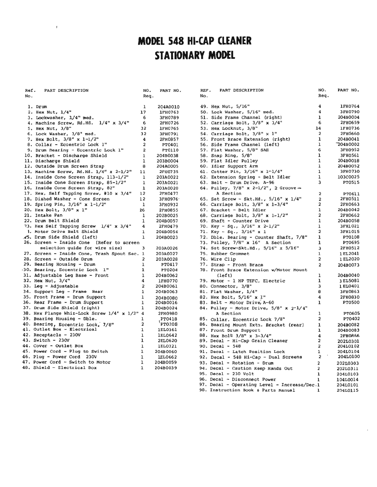
MODEL
548
HI-CAP
CLEANER
STATIONARY
MODEL
\
\ \
16
17
18
~
-
27-.
]I
26
2 .-."'-.
_-00
• - \
_0-
-
~
____
.,'='.-1_
0
,.
--"r-
I
,----->
/3
14
--'-i-,------'
15
88
MODEL
548
HI-CAP
CLEANER
STATIONARY
MODEL
Ref.
PART
DESCRIPTION
NO.
No.
Req.
1.
Drum 1
2.
Hex
Nut,
1/4"
17
3.
Lockwasher,
J.!4" DIed. 6
4.
Machine
Screw,
M.Hd.
1/4"
x
3/4"
6
5.
Hex
Nut,
3/8"
32
6.
Lock
Washer,
3/8"
med.
32
7.
Hex
Bolt,
3/8"
x
1-1/2"
4
8.
Collar
-
Eccentric
Lock
1"
2
9.
Drum
nearing
-
Eccentric
Lock
1"
2
10.
Bracket
-
Discharge
Shield
1
11.
Discharge
Shield
1
12.
OUtside
Drum
Screen
Strap
8
13.
Machine
Screw,
Rd.Hd.
1/4"
x
2-1/2"
11
14.
Inside
Cone
Screen
Strap,
113-1/2"
1
15.
Inside
Cone
Screen
Strap,
85-1/2"
1
16.
Inside
Cone
Screen
Strap,
82"
1
17.
Hex,
Self
Tapping
Screw,
1110
x
3/4"
12
18.
Dished
Washer
-Cone
Screen
12
19.
Spring
Pin,
3/16"
x
1-1/2"
1
20.
Hex
Bolt,
3/8"
x
1"
26
21.
Intake
Pan
1
22.
Drum
Belt
Shield
1
~3.
Hex
Self
Tapping
Screw
1/4"
x
3/4"
4
I.
Motor
Drive
Belt
Shield
1
.-6.
Drum
Side
Shield
(left)
1
26.
Screen
-
Inside
Cone
(Refer
to
screen
selection
guide
for
wire
si~e)
3
27.
Screen
-
Inside
Cone,
Trash
Spout
Sec.
1
28.
Screen
-
OUtside
Drum 2
29.
Bearing
Housing
-Drum 1
·30.
Bearing,
Eccentric
Lock
1"
1
31.
Adjustable
Leg
Base
-
Front
1
32.
Hex
Nut,
3/4"
4
33.
Leg -
Adjustable
2
34.
Support
Leg -
Frame
Rear
1
35.
Front
Frame
-Drwn
Support
1
36.
Rear
Frame
-Drum
Support
1
37.
Drum
Side
Shield
(right)
1
38.
Hex
Flange
Whi~-Lock
Screw
1/4"
x
1/2"
4
39.
Bearing
lIousing
-
Db1e.
1
40.
Bearing,
Eccentric
Lock,
7/8"
2
41.
Outlet
Box -
Elec
trical
1
42.
Receptacle
-230V 1
43.
Switch
-230V 1
44.
Cover
-
OUtlet
Box 1
45.
Power
Cord
-
Plug
to
Swi
tch
1
46.
Plug
-
Power
Cord
230V 1
47.
Power
Cord
-
Switch
to
Motor
1
48.
Shield
-
Electrical
Box 1
PART
NO.
2Q4A0010
1FH0763
3FH0789
2FH0726
1FH0765
3FH0791
2FH0857
PT0401
PTOllO
20480038
203B0004
204AO005
2Ffl0735
203A0022
203A0021
203A0020
2FH0477
3FH0976'
3FH0932
2FH0855
202B0025
204B0057
2FH0479
204B0054
204B0023
203A0026
203A0027
203A0028
PT0417
PT0204
204B0062
IFH0770
204B0061
204B0063
204B0080
204B0016
204B0024
2FH0980
PT0418
IpTO?oa
lEL0361
lEL0642
2EL0620
lEL0321
204B0060
lEL0662
204B0059
204B0039
REF'.
PART
DESCRIPTION
NO.
No.
Req.
49.
Heit
Nut,
5/16"
4
50.
Lock
Washer,
5/16"
med.
4
51.
Side
Frame
Channel
(right)
1
52.
Carriage
Bolt,
3/8"
x
3/4"
6
53.
Hex
Locknut,
3/8"
14
54.
Carriage
Bolt,
3/8"
x
1"
2
55.
Front
Brace
Extension
(right)
1
56.
Side
Frame
Channel
(left)
1
57.
Flat
Washer,
5/8"
SAE
6
58.
Snap
Ring,
5/8"
1
59.
Flat
Idler
Pulley
1
60.
Idler
Support
Arm
1
61.
Cotter
Pin,
3/16"
x
1~1/4"
1
62.
Extension
Spring
-
Belt
Idler
1
63.
Belt
-Drum
Drive,
A-96
3
64.
Pulley,
7/8"
x
2~1/2",
2
Groove-
A
Section
2
65.
Set
Screw
-
Skt.Hd.,
5/16"
x
1/4"
2
66.
Carriage
Bolt,
3/8"
x
1-3/4"
2
67.
Bracket
-
Belt
Idler
1
68.
Carriage
Bolt,
3/8"
x
1-1/2"
2
69.
Shaft
-
Counter
Drive
1
70.
Key -
sq.,
3/16"
x
2-1/2"
1
71.
Key -
sq.,
3/16"
x 1 2
72.
Dble.
Bearing
-
Counter
Shaft,
7/8"
1
73.
PUlley,
7/B"
x
16"
A
Section
1
74.
Set
screw-Skt.Hd.,
5/16"
x
5/16"
3
75.
Rubber
Grommet 1
76.
Wire
Clip
2
77.
Strap
-
Front
Brac~
2
78.
Front
Brace
Extension
w/Motor
Mount
(left)
1
79.
Motor
- 1
HP
TEFC,
Electric
1
80.
Connector,
3/8"
3
81.
Flat
washer,
1/4"
8
82.
Hex
Bolt,
5/16"
x
I"
4
83.
Belt
-
Motor
Drive;
A-60
1
84.
Pulley
-.
Motor
Drive,
5/8"
x
2-1/4"
A
Section
1
85.
Collar.
Eccentric
Lock
7/8"
2
86.
Bearing
Mo~nt
Ext~.
Bracket
(rear)
1
87.
Front
Drum
Support
1
88.
Hex
Bolt
3/8"
x
3-3/4"
4
89.
Decal
-
Hi-Cap
Grain
Cleaner
2
90.
Decal
-
548
2
91.
Decal
-
Latch
position
Lock
1
92.
Decal
-
548
Hi-Cap
-
Dual
Screens
2
93.
Deca
1 -
Rota
tion
-Drum 2
94.
Decal
-
Caution
Keep
Hands
Out
2
95.
Decal
-
230
Volt
1
96.
Decal
-
Disconnect
Power
1
97.
Decal
-
Operating
Level
-
Increase/Dec.1
98.
Instruction
Book "
Parts
Manua::' 1
PART
NO.
1FH0764
3FH0790
204B0004
2FH0659
IFH0736
2FH0660
204B0041
"'204B0002
3FH0952
3FH0561
204B0018
204B0052
3FH0730
103C0025
PTOSIS
PT06),1
2FH05ll
2FH0663
204B0042
2FH0662
204B0058
3FHl021
3FHI015
PTOI08
PT0695
2FH0512
1EL2041
1 EL2020
204B0073
20480040
3 EL5081
1 EL0401
3FH0863
2FIl0830
PT0500
PT0605
PT0402
20480082
204B0083
2FHMfifi
202L0301
204L0102
204LOI04
204L0100
202L0303
202L0311
204LOI03
104L0014
204LOIOl
204L01l5

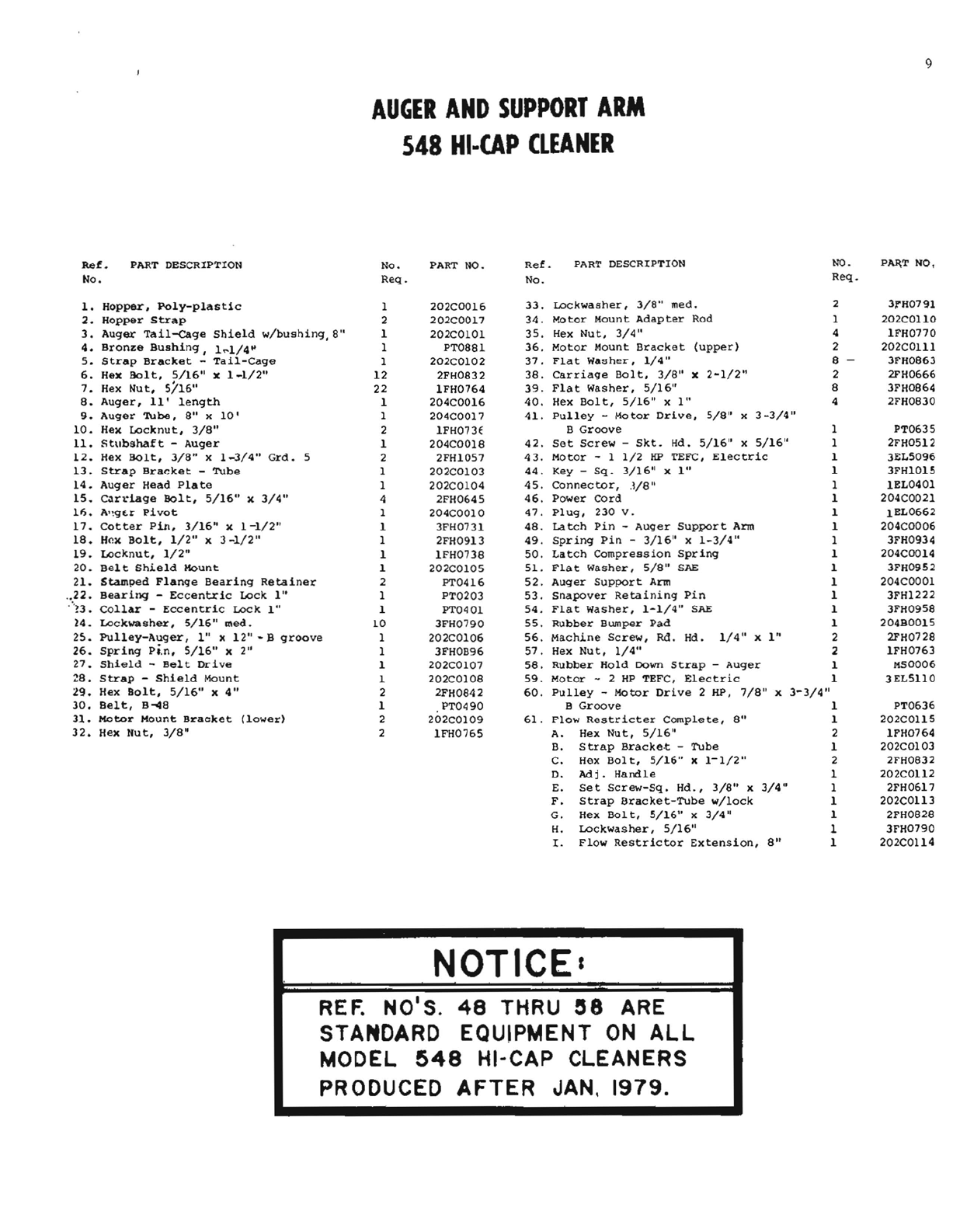
AUGER
AND
SUPPORT
ARM
548
HI
..
CAP
CLEANER
27--~
__
i
I
I
[§iJ
9
AUGER
AND
SUPPORT
ARM
548
HI-CAP
CLEANER
Ref.
PART DESCRIPTION
No.
PART NO.
Ref.
PART
DESCRIPTION
NO.
P~T
NO.
No.
Req.
No.
Req.
33.
Lockwasher,
3/8"
med.
2 3""H0791
1.
Hopper,
Poly-plastic
2.
Hopper
Strap
3.
Auger
Tail-<:age
Shield
w/bushing,8"
4.
Bronze
Bushing,
1~1/4~
5.
Strap
Bracket
-
Tail-Cage
1
2
1
1
1
202C0016
34.
Motor
Mount
Adapter
Rod 1
202COI10
202C0017
35.
Hex
Nut,
3/4"
4
1FH0770
202COIOl
PT0881
36.
Motor
Mount
Bracket
(upper)
2
202COll1
202C0102
37.
Flat
Washer,
1/4"
8
3FH0863
6.
Hex
Bolt,
5/16"
x
1-1/2"
12
2FH0832
38.
Carriage
Bol
t,
3/8"
x
2-1/2"
2
2FH0666
7.
Hex
Nut,
5/16"
22
1FH0764
39.
Flat
Washer,
5/16"
8
3FH0864
8.
Auger,
11'
length
9.
Auger
Tube,
8"
x
10'
10.
Hex
Locknut,
3/8"
11.
Stuhshaft
-
Auger
12.
Hex
Bolt,
3/8"
x
1-3/4"
Grd.
5
13.
Strap
Bracket
-
Tube
14.
Auger
Head
Plate
1
1
2
1
2
1
1
204C0016
40.
Hex
Bolt,
5/16"
xl"
4
2FH0830
204C0017
41.
pulley
-
Motor
Drive,
5/8"
x
3-3/4"
B
Groove
1
PT0635
42.
Set
Screw
-
Skt.
Hd.
5/16"
x
5/16"
1
2FH0512
43.
Motor
- 1
1/2
HP
TEFC,
Electric
1
3EL5096
1FH073E
204C0018
2FHI057
202C0103
44.
Key
-
Sq.
3/16"
x
1"
1
3FHI015
202COI04
45.
Connector,
.lI8"
1
1EL0401
15.
C.1n·iage
Bolt,
5/16"
x
3/4"
4
2FH0645
46.
Power
Cord
1
204C0021
11;.
A'~gE.r
pivot
17.
Cotter
Pin,
3/16"
x
1-1/2"
18.
Hl'lx
Bolt,
1/2"
x
3-1/2"
19.
Locknut,
1/2"
20.
Belt
Shield
Mount
21.
Stamped
Flange
Bearing
Retainer
..
22.
Bearing
-
Eccentric
Lock
1"
···?3.
Collar
-
Eccentric
Lock
1"
1
1
1
1
1
2
1
1
204COOI0
47.
Plug,
230
V.
1
lEL0662
3FH0731
48.
Latch
Pin
-
Auger
Support
Arm 1
204C0006
2FH0913
49.
Spring
Pin
-
3/16"
x
1-3/4"
1
3FH0934
1FH0738
50.
Latch
Compression
Spring
1 204COO14
202C0105
51.
Flat
washer,
5/8"
SAE 1
3FH0952
PT0416
52.
Auger
Support
Arm 1 204COOOl
PT0203
53.
snapover
Retaining
Pin
1
3FH1222
PT0401
54.
Flat
Washer,
1-1/4"
SAE 1
3FH0958
24.
Lockwasher,
5/16"
med.
10
3FH0790
55.
Rubber
Bumper
Pad
1
204B0015
25.
Pulley-Auger,
I"
x
12"-S
groove
26.
Spring
pi.n,
5/16"
x
2"
27.
Shield
-
Belt
Drive
Z8.
Strap
-
Shield
Mount
:l9.
Hex
Bolt,
5/16"
x
4"
30.
Belt,
B-.48
31.
!'IOtor
Mount
Bracket
(lower)
1
1
1
1
2
1
2
202COI06
56.
Machine
Screw,
Rd.
Hd.
1/4"
x
1"
2
2FH0728
3FHOB96
57.
Hex
Nut,
1/4"
2
1FH0763
202COI07
58.
Rubber
Hold
DOwn
Strap
-
Auger
1
MS0006
202COI08
59.
Motor
- 2
HP
TEFC,
Electric
1
3EL5110
2FH0842
60.
Pulley
-
Motor
Drive
2 HP,
7/8"
x
3-3/4"
PT0490
B
Groove
1
PT0636
202COI09
61.
Flow
Restricter
Complete,
8"
1
202C01l5
32.
Hex
Nut,
3/8"
2
IFH0765
A.
Hex
Nut,
5/16"
2
1FH0764
B.
Strap
Bracke·t
-
Tube
1
202COI03
C.
Hex
Bolt,
5/16"
x
1-1/2"
2
2FH0832
D.
Adj.
Handle
1
202C01l2
E.
Set
Screw-sq.
Hd.,
3/8"
x
3/4"
1
2FH0617
F.
Strap
Bracket-Tube
w/10ck
1
202C01l3
G.
Hex
Bolt,
5/16"
x
3/4"
1
2FH0828
H.
Lockwasher,
5/16"
1
3FH0790
1.
Flow
Restrictor
Extension,
8"
1
202C01l4
NOTICEs
REF:
NO'S.
48
THRU ee
ARE
STANDARD EQUIPMENT
ON
ALL
MODEL
548
HI-CAP CLEANERS
PRODUCED
AFTER
JAN,
1979.

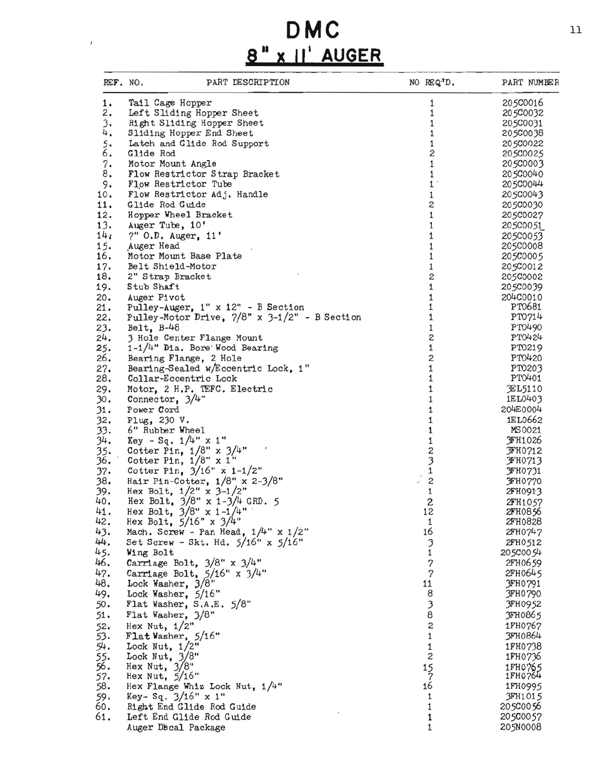
10
DMC
8
II
X
II'
AUGER
:0.
37
9
~
11
ER
REF.
NO.
PART
DESCRIPTION
NO
REQ"D.
PART
NUMIER
1.
Tail
Cage
Hopper
1
205COO16
2.
Left
Sliding
Hopper
Sheet
1 205COO)2
3.
Right
Sliding
Hopper
Sheet
1 205C00)1
4.
Sliding
Hopper
End
Sheet
1 205C0038
5.
Latch
and
Glide
Rod
Support
1
205COO22
6.
Glide
Rod 2 205C0025
7.
Motor
Mount
Angle
1
205COO03
8.
Flow
Restrictor
Strap
Bracket
1 205C0040
9.
Flpw
Restrictor
Tube
l'
205COO44
10.
Flow
Restrictor
Adj.
Handle
1 205C0043
11.
Glide
Rod
Guide
2 205C0030
12.
Hopper
Wheel
Bracket
1 205C0027
1).
Auger
Tube,
10'
1 205C0051
14,
7"
a.D.
Auger.
11'
1 205C0053
15.
,Auger Head 1
205COOOS
16.
Motor
Mount
Base
Plate
1
205COO05
17.
Belt
Shield-Motor
1
205COO12
18.
2"
Strap
Bracket
2
205COO02
19.
Stub
Shaft
1 205C0039
20.
Auger
Pivot
1 204C0010
21.
Pulley-Auger,
1"
x
12"
- B
Section
1 PT06S1
22.
Pulley-Motor
Drive,
7/S"
x
)-1/2"
- B
Section
1 PT0714
23.
Belt,
B-48
1 PT0490
24.
3
Hole
Center
Flange
Mount 2 PTQ424
25.
1-1/4"
Dia.
Bore'
Wood
Bearing
1 PT0219
26.
Bearing
Flange,
2
Hole
2 PT0420
27.
Bearing-Sealed
w/Eccentric
Lock,
1"
1 PT0203
28.
Collar-Eccentric
Lock
1 PTQ401
29.
Motor,
2
H.P.
!EFC.
Electric
1 JEL5110
30.
Connector,
3/4"
1 1EL0403
31.
Power
Cord
1 204EOO04
32.
Plug,
230
V.
1 lEL0662
33.
6"
Rubber
Wheel 1
MS0021
34.
Key -
Sq.
1/4"
x
1"
1 )FH1026
35.
Cotter
Pin,
1/8"
x
3/4"
2 3FH0712
36.
Cotter
Pin,
1/8"
xl"
3 )FH0713
37.
Cotter
Pin,
3/16"
x
1-1/2"
1 )FH0731
38.
Hair
Pin-Cotter,
1/8"
x
2-3/S"
, 2 )FH0770
39.
Hex
Bolt.
1/2"
x
3-1/2"
1 2FH091J
40.
Hex
Bolt.
3/8"
x
1-3/4
GRD.
5 2 2FH1057
41.
Hex
Bolt,
3/8"
x
1-1{4"
'
12
2FH0856
42.
Hex
Bolt,
5/16"
x
3/
" 1
2FHOS28
43.
Mach.
Screw
-
Pan
Head.
1/4"
x
1/2"
16 2FH0747
44.
Set
Screw
-
Skt.
Hd.
5/16"
x
5/16"
3 2FH0512
45.
Wing
Bolt
1 205COO54
46.
Carriage
Bolt,
3/S" x
3/4"
7 2FH0659
47.
48.
Carriage
BOlt,/s/16"
x
3/
4"
Lock
Washer,
3
8"
7
11
2FH0645
)FH0791
49.
Lock
Washer.
5/16"
S 3FH0790
50.
Flat
Washer,
S.A.E.
5/8"
3 3FH0952
51.
Flat
Washer,
3/S"
S )FH0865
52.
Hex
Nut.
1/2"
2 lFH0767
53.
Flat
Washer.
5/16"
1
3FHOS64
54.
Lock
Nut.
1/2"
1 lFH073S
55.
Lock
Nut.
%8"
2 lFH0736
56.
57.
Hex
Nut,
3
8"
Hex
Nut,
5/16"
15
7
lFH076,
lFH076
58.
Hex
Flange
Whiz
Lock
Nut.
1/4"
16 lFH0995
59.
Key-
Sq.
3/16"
xl"
1 JFH1015
60.
Righ.t End
Glide
Rod
Guide
1
205COO56
61.
Left
End
Glide
Rod
Guide
1 205C0057
Auger
DBcal
Package
1 205N000S
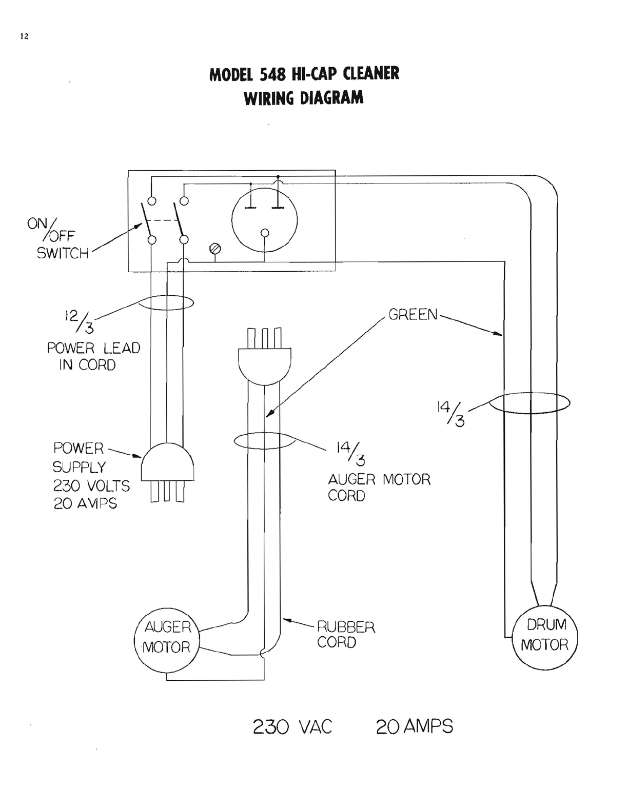
12
MODEL
548
HI-CAP
CLEANER
WIRING
DIAGRAM
GR.EEN~
ONI
IOFF
SWITCH
12/
3
POWER
LEAD
IN
CORD
POWER
----...
SUPPLY
230
VOLTS
20
AMPS
141
3
AUGER
MOTOR
CORD
---RUBBER
CORD
230
VAC
20
AMPS

19
MODEL
548
CLEANER
OVERALL
DIMENSIONS
62/
1
/I
82
1/
"
72
104
RETRACTED
HOPPER
.....---:-;-;;:~~~~==---=~=-=-=----r.-----
'10
II
---~
112
1/2"
EXTENDED
HOPPER

20
WARRANTY
The Hi-Cap
Grain
Cleaner
is
guaranteed
for. a
period
of
one
year,
to
be
free
of
defects
in
material
or
workmanship,
when
properly
installed
and
operated
i"n
accordance
':"'ith
the
instructions.
Warranted
parts
will
be
exchanged
FOB,
Mason
City,
Iowa
without
charge
to
the
user.
Damage
resulting
from
n€.gligence
voids
the
warranty.
Warranty
DOES NOT
INCLUDE
LABOR, INSTALLATION OR
DELIVERY
OF REPLACEMENT PARTS.
Electric
motors
are
covered
by
the
warranties
of
the
respective
manufacturers.
Electric
service
centers
are
located
in all
regions.
Consult
your
dealer.
The Hi-Cap
Warranty,
and
the
liability
of
David
Manufacturing
Company,
its
distributors,
dealers,
and
agents
is
limited
to
replacement,
without
charge
of
defective
parts,
as
outlined
above.
No
other
warranties,
express
or
implied,
shall
apply,
in
any
circumstances.
The
manufacturer
reserves
the
right
to
make
changes
in
specifications
or
prices
without
incurring
obligation
on
previously-produced
merchandise.
Important
Data!
SERIAL
NUMBER
YEAR
PURCHASED---------
_
DEALER--------
Addressli-- _
Phone
#----------------

DMOl3

CroProcessing
Equipment
Table of contents
Popular Industrial Equipment manuals by other brands


Daktronics
Daktronics M Series Operation manual

Siemens
Siemens RM400 C Series operating manual

Tronair
Tronair 06-4035-3600 Operation & service manual

schmersal
schmersal PSC1 Series installation manual

Rapid Packaging
Rapid Packaging Eastey Value Series user guide

Cargo Floor
Cargo Floor CF500 SL-2 Replacement instructions


