K R E B E R
5
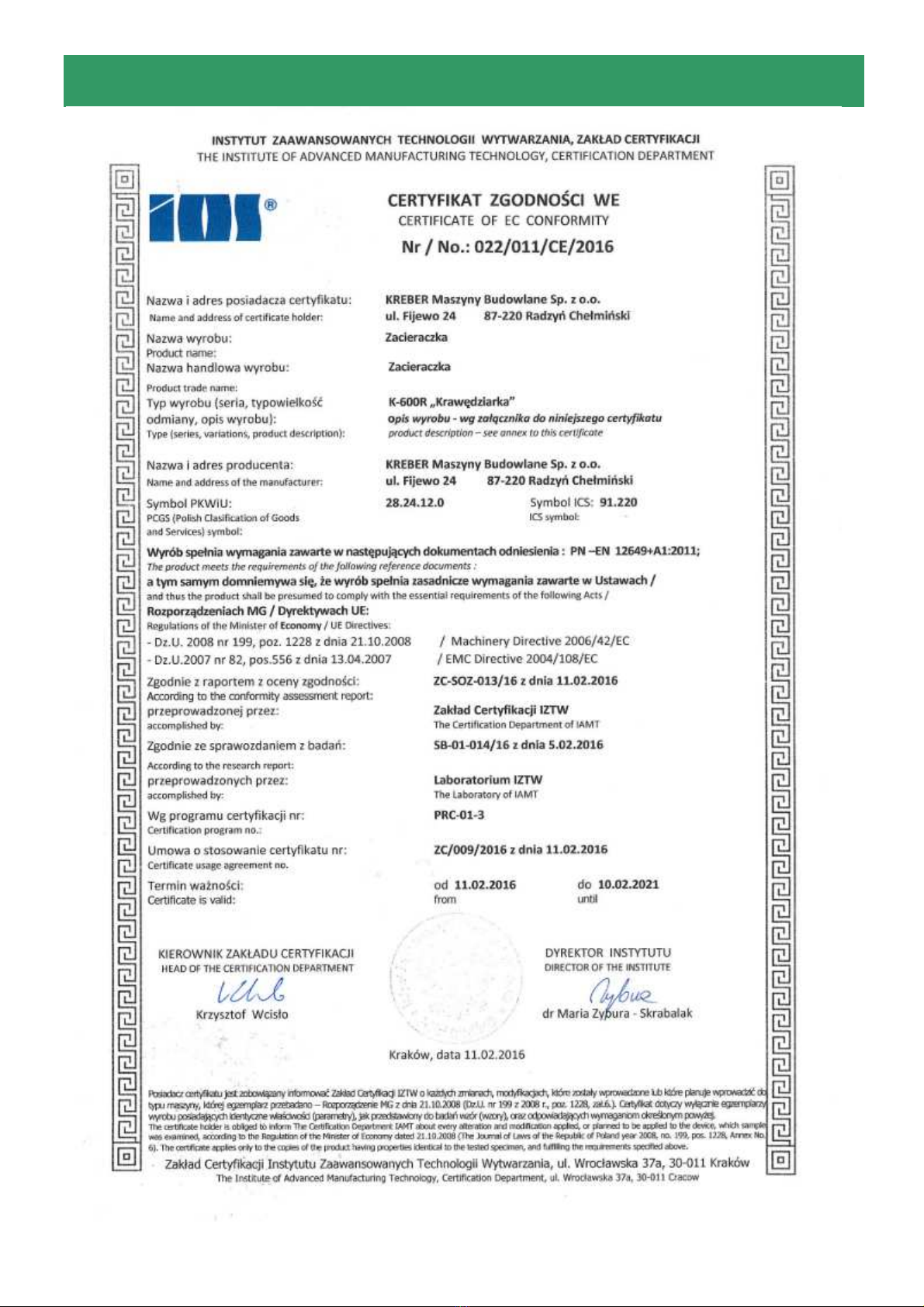
1. Intended use and scope of application
K-600 R trowel is used for trowelling and smoothing resin, concrete and surface
hardening floors. The used electric engine allows to work in closed unventilated rooms
which is not recommended for combustion engine machines. Quick and easy replacement
of blades and trowelling disc greatly facilitates operation and influences work efficiency.
2. Safety instructions
- An employee who has read the operating instructions may be allowed to work with
the trowel.
- Check the technical condition of the trowel before each start-up!
- It is forbidden to work with a machine that has damaged or disassembled covers
and protection elements.
- The operator should use ear protectors when working with the machine.
- Provide adequate ventilation of the rooms during work. The exhaust gas
contains toxic carbon monoxide. It is a colourless and odourless gas that can cause
loss of consciousness or death!!
- It is forbidden to use the machine in closed and potentially explosive rooms!!
- Stop the engine before each refuelling. In case of a fuel spill, remove it thoroughly
and do not start the engine before the residual fuel vapours evaporate.
- There is no risk of mechanical vibrations during the operation of the trowel.
- Do not use open fire during work and refuelling.
- Before starting troweling, check if the surface on which the machine is to work is
free from so-called "Foreign bodies" such as nuts, bolts, metal parts, protruding
reinforcement or expansion joints. They can cause serious damage to the machine and
endanger persons in the vicinity of the machine as well as the operator.
- The machine may only be transported with the engine switched off and the plate
removed.
- All maintenance work should only be carried out with the engine switched off.
- Repairs and overhauls may only be carried out by an authorized service centre or
the manufacturer.
The machine may not be used for work that is not in accordance with its
intended use!
DISREGARD OF THE ABOVE RECOMMENDATIONS MAY LEAD TO
SERIOUS DAMAGE TO HEALTH AND LOSS OF LIFE.