500224R07
DAVISCOMMS (S) PTE LTD
Daviscomms Confidential
CONTENT
PAGE
CONTENT PAGE
1. SYSTEM OVERVIEW 1
1.1 EAZITRAC 1000.......................................................................................................................................1
1.2 UNDERSTANDING THE PRODUCT MODEL OF YOUR HARDWARE ...............................................................2
1.3 PARTS DESCRIPTION OF EAZITRAC 1000.................................................................................................4
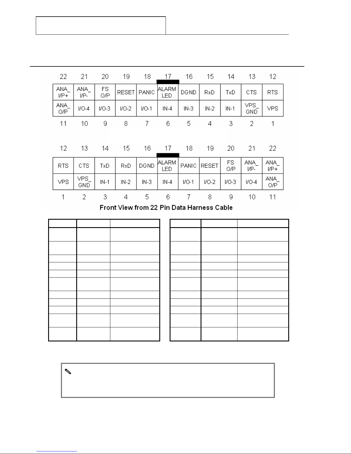
1.4 PIN LAYOUT DESCRIPTION........................................................................................................................4
1.4 PIN LAYOUT DESCRIPTION........................................................................................................................5
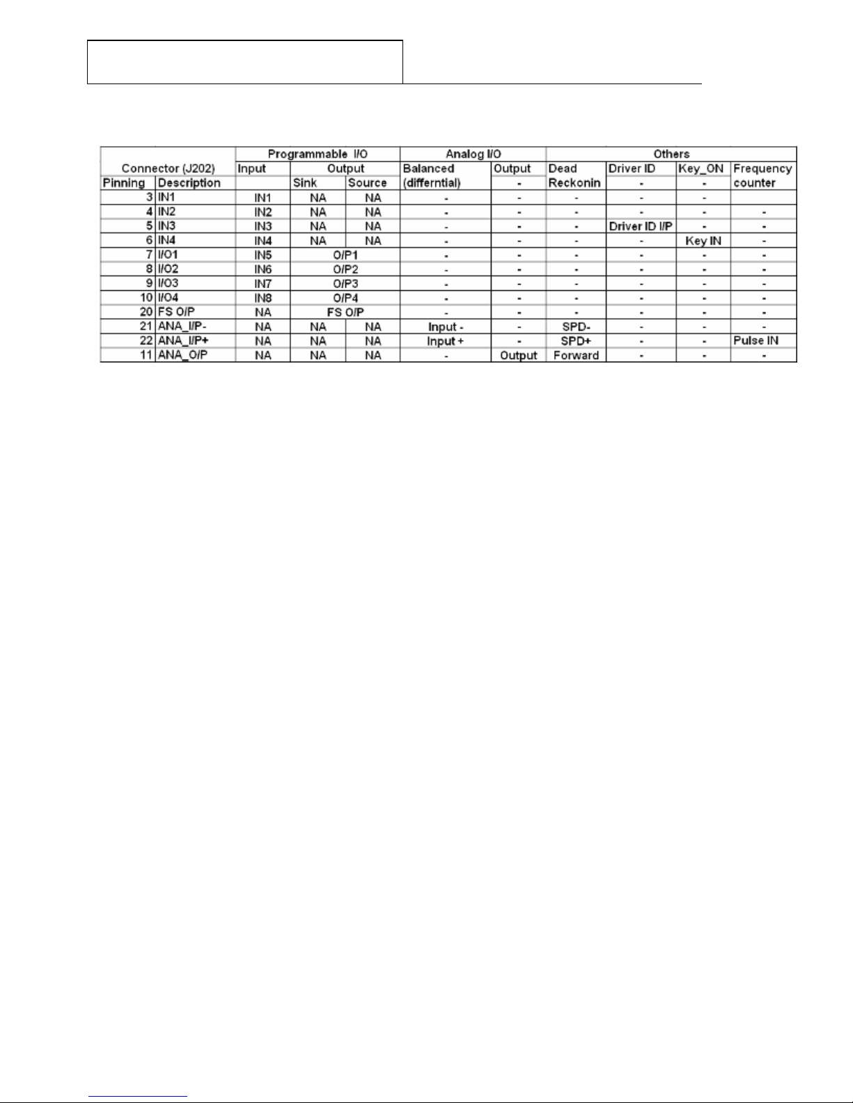
1.5 I/O PORT DEFINITION OVERVIEW...............................................................................................................7
7
REMARKS 7
(1) WITH DRIVER ID, IN3 CANNOT BE USED AS INPUT....................................................................................7
(2) ANALOG I/P AND DEAD RECKONING SHARE THE SAME PORTS,HENCE BOTH FEATURES CANNOT BE
IMPLEMENTED AT THE SAME TIME .......................................................................................7
1.6 OPERATING VOLTAGE AND TEMPERATURE...............................................................................................7
2. PRODUCT PACKAGE OVERVIEW 8
2.1 EAZITRAC 1000 DEVICE WITH OPTIONAL ACCESSORIES.........................................................................8
2.2 INSTALLATION AND STARTING UP ON THE EAZITRAC 1000..................................................................11
2.3 LED INDICATORS....................................................................................................................................14
3. INTERFACING THE EAZITRAC 1000 FOR AT COMMANDS COMMUNICATION 15
3.1 HYPERTERMINAL SETTINGS....................................................................................................................15
4. TERMINOLOGY 18
4.1 GSM……………………………………………………………………………………………………18
4.2 SIM CARD ............................................................................................................................................18
4.3 GPS……………………….....................................................................................................................18
4.4 GPRS……………..................................................................................................................................18
4.5 SMS……………....................................................................................................................................18
4.6 HYPERTERMINAL....................................................................................................................................18
5. APPLICATION EXAMPLES 19
5.1 EXAMPLE 1: RETRIEVING GPS DATA REMOTELY ON THE EAZITRAC 1000 WITHOUT THE USE OF A SIM
CARD .................................................................................................................................19
5.2 EXAMPLE 2: TO PROGRAM THE EAZITRAC 1000 TO RECEIVE DATA AND REPORTS VIA SMS.................20
5.3 EXAMPLE 3: CONFIGURING THE EAZITRAC 1000 TO SEND AN OUTPUT TO RELAY DEVICE AND DISABLE
THE FUEL PUMP OF THE VEHICLE........................................................................................23
5.4 EXAMPLE 4: PROGRAMMING THE EAZITRAC 1000 TO LOG SR MESSAGES TO MEMORY WHEN GPS
LOCATION IS FIXED AND DUMPING THE SR MESSAGES TO A TEXT FILE ..............................25
6. APPENDIX A 30