daviteq WS433-LPC User manual
WS433-LPC-MN-EN-01
FEB-2022
SKU
WS433-LPC
HW Ver.
2.5
FW Ver.
6.01
Item Code
WS433-LPC-01
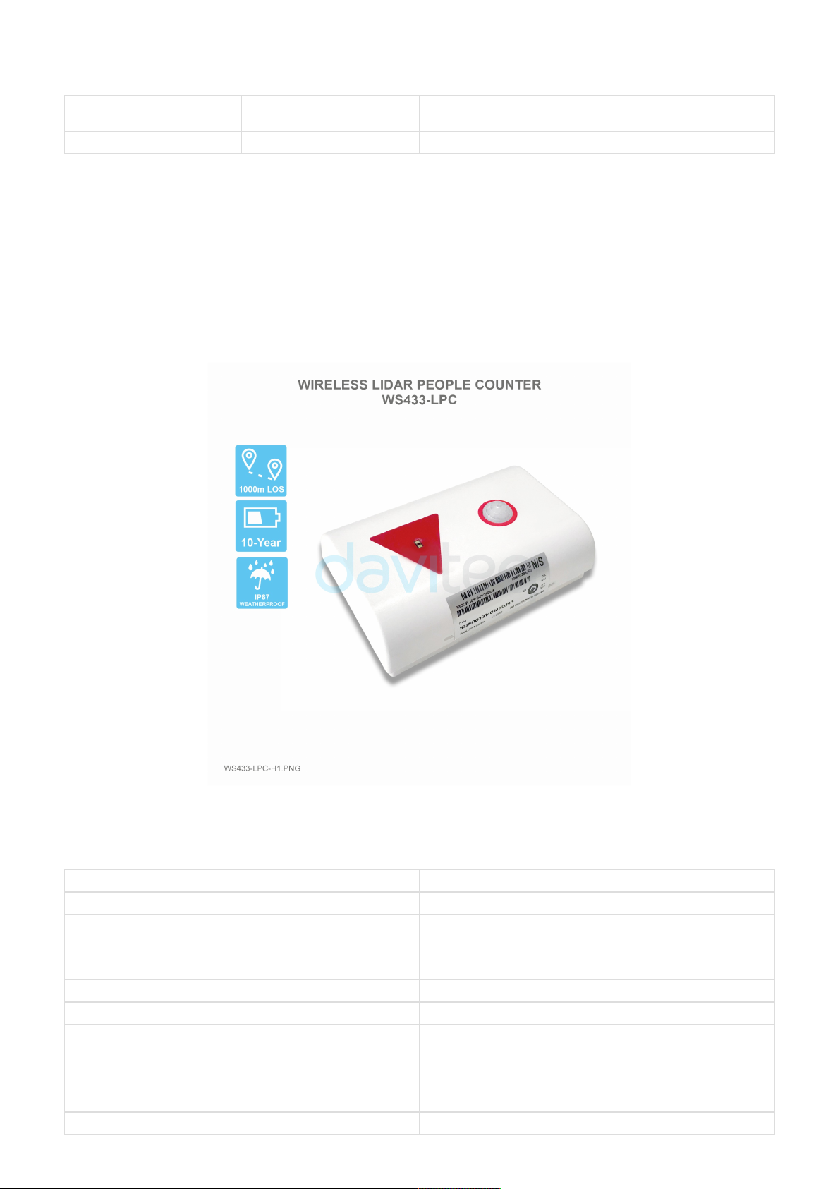
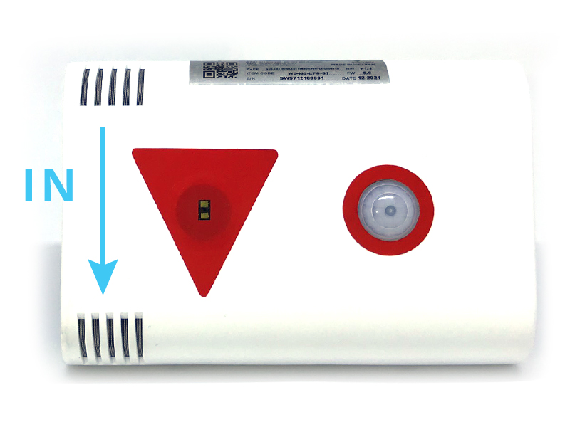
WIRELESS LIDAR PEOPLE COUNTER, 433MHZ, TYPE AA BATTERY 1.5VDC, IP5X
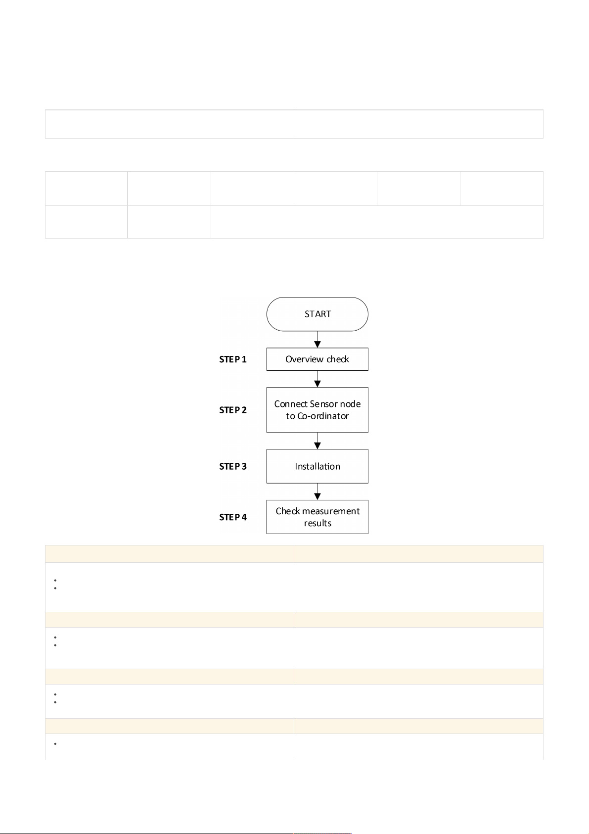
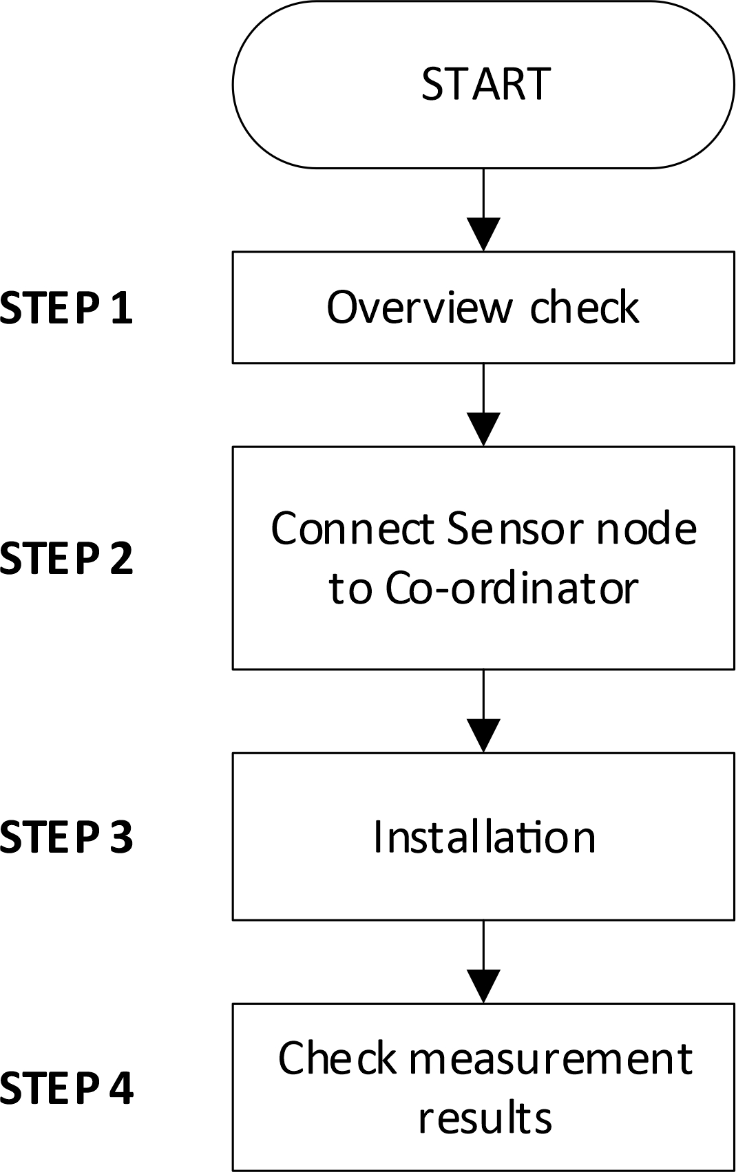
Step 1: Overview check
Check cope of delivery
Make sure the device shows no signs of damage
Refer to section 5 for details
Step 2: Connect Sensor node to Co-ordinator
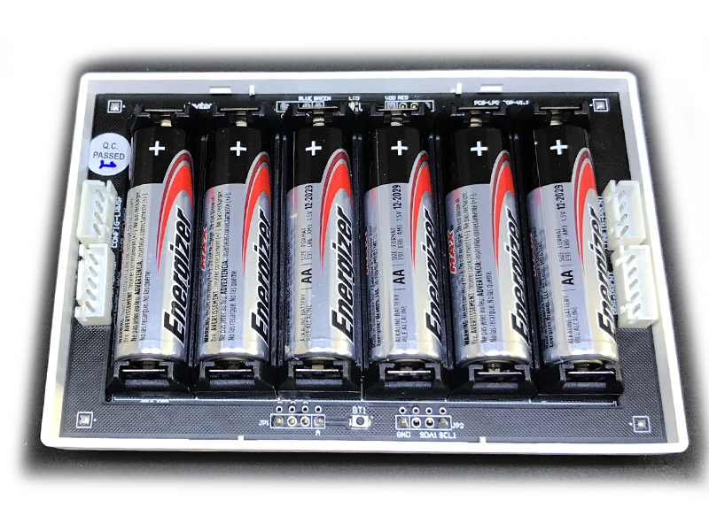
Make sure that the battery is installed properly
Follow every steps Add sensors node to Co-ordinator WS433-CL
or with iConnector integrated Co-ordinator
Refer to section 6.3 for details
Step 3: Installation
Make sure compliance with manufacturer's recommendations
Make sure the correct measuring range
Refer to section 6 and section 7 for details
Step 4: Check measurement results
Check the reliability of the measurement compared with reality
USER GUIDE FOR WIRELESS LIDAR
PEOPLE COUNTER WS433-LPC
This document is applied for the following products
0. Configuration Check List
HW Ver.
FW Ver.
Release Date
Functions Change
1.1
5.00
FEB-2022
WS433-LPC is a sensor with built-in advanced Lidar sensor to detect and ranging people. It can count the people walk
thru with accuracy higher than 95%. The sensor is not affected by temperature, humidity, RF noise and less affected
by ambient light... The wireless portion is Sub-GHz technology from Texas Instruments allows long range transmission
at ultra-low power consumption. It will connect 2-way wirelessly to the wireless co-ordinator WS433-CL to send data
and receiving the configuration. It can be configured the operation parameters like data sending interval, health check
cycle...remotely from Globiots platform or via ModbusRTU software (thru the WS433-CL). Its default data rate is 50
kbps, can be switched to 625 bps to increase the communication range. The sensor can last up to 5 years with type AA
battery. Typical Applications: People counter for public toilet, People counter for Store, shop, …
SENSOR SPECIFICATION
Sensor technology
Lidar
Detection range
max 4m
Detection cone
27 degree
Working temperature
-40 .. + 60 oC
Working humidity
0 .. 100% RH, non-condensing
WIRELESS SPECIFICATION
Data speed
Up to 50kbps
Transmission distance, LOS
1000m
Antenna
Internal Antenna
Functions
Sending data in interval or when alarms occur
Battery
Battery AA Type 1.5VDC and 7..48VDC (AC adapter not included
1. Functions Change Log
2. Introduction
3. Specification
Frequency Band
ISM 433MHz, Sub-GHz technology from Texas Instrument, USA
International Compliance
ETSI EN 300 220, EN 303 204 (Europe) FCC CFR47 Part15 (US), ARIB
STD-T108 (Japan)
Vietnam Type Approval Certification
QCVN 73:2013/BTTTT, QCVN 96:2015/BTTTT (DAVITEQ B00122019)
Security Standard
AES-128
Operating temperature of PCB
-40oC..+60oC (with Lithium Ultimate AA battery)
Housing/Protection
Self-extinguisher ABS, Dust and vapor protection
Mounting
Ceiling mount
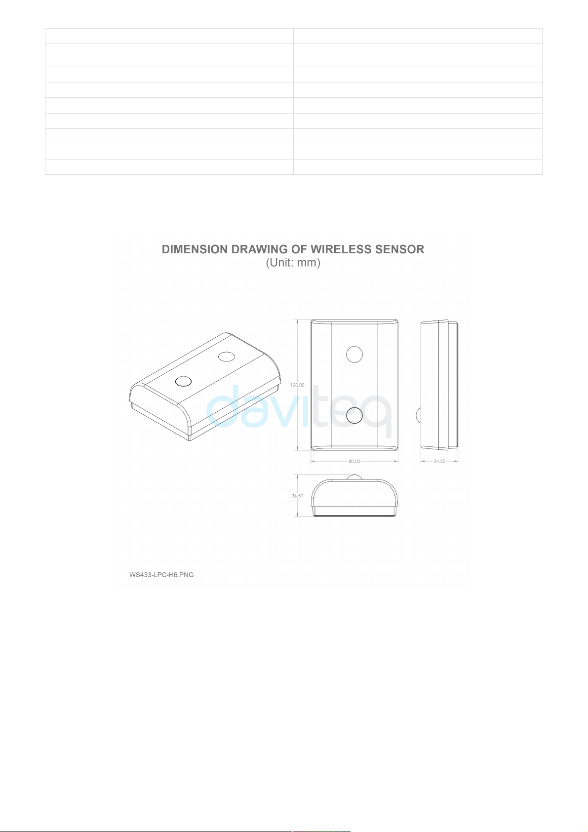
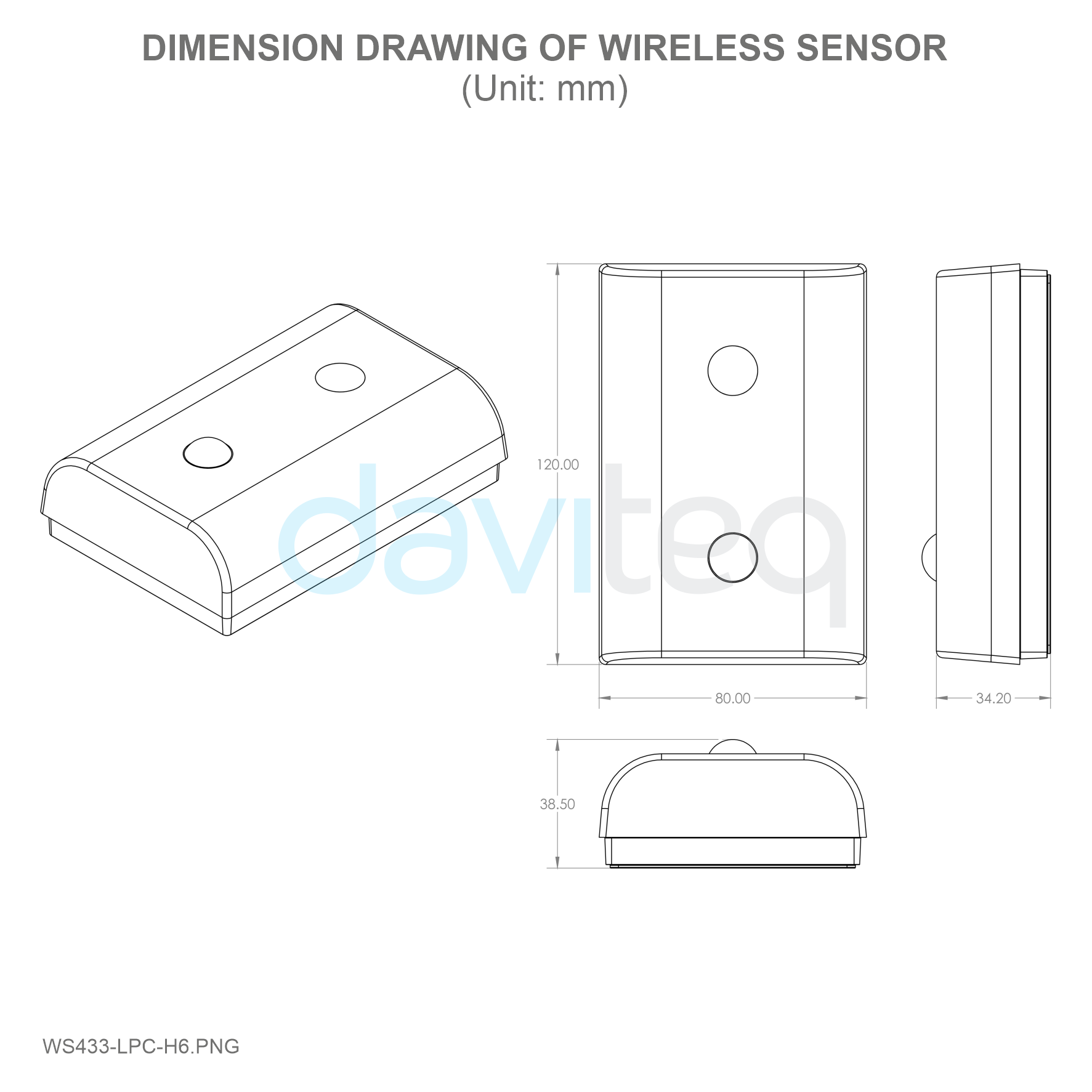
Dimension
H120xW80xD45
Net weight
≺150 grams
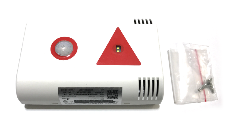
1. Wireless sensor
2. Screws
4. Dimensions
5. Scope of delivery

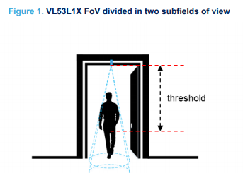
Counting people with the VL53L1X consists of using the multiple zones of the sensor receiving SPAD area, and of
configuring it with two distinct fields of view (FoV), to alternatively get a ranging distance from them and consequently
recognize the movements of a person. Using this method, the number of people occupying a meeting room, accessible
from a reasonably narrow access, is known at all times by detecting the entrances and exits of the attendees.
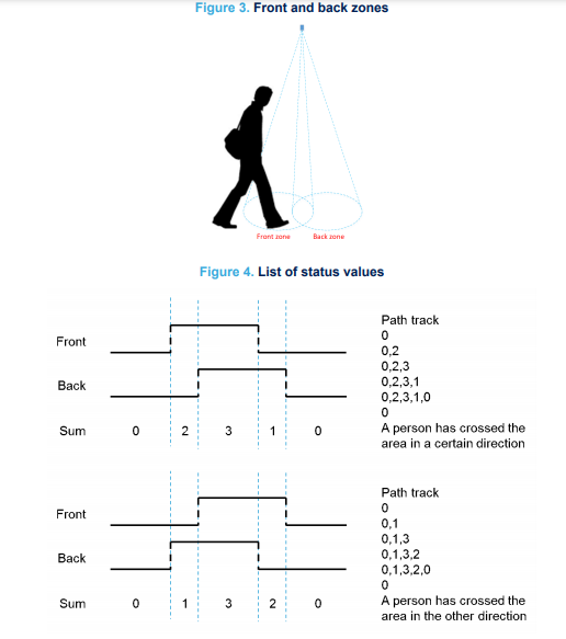
By measuring and analyzing the distances of targets within the FoVs of a front and back zone (see figure below and
Figure 3. Front and back zones), a simple algorithm can detect the direction a person crosses the area under the two
FoVs. This algorithm "understands" that someone is under one of the FoV as long as the distance measured by the
sensor under this FoV is between 0 and a threshold value specified in mm.
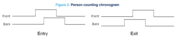
From a timing perspective, the sensor alternatively ranges on each of the two zones, for a very short period of time in
milliseconds. It is possible to determine in which direction a person crosses the area, depending in which order this
person has been detected in the two zones, as shown in the figure below.
The counting algorithm example relies on a list of states that have to occur in a certain order to detect if a person has
crossed the specified area and in which direction this area has been crossed. These states are stored in a list and
compared to two default lists of states that represent how the area is crossed in two different directions. When no-one
is seen in either of the two zones, the list of states is reset.
6. Operation Principle
6.1 The principle of counting people
6.1.1 Overview
6.1.2 Algorithm description

If we consider that a person detected in the front zone equals 2, and a person detected in the back zone equals 1, the
algorithm adds the value of the two states and stores the result as soon as it changes.
Eventually, if the consecutive states in the list are 0, 1, 3, 2, 0 or 0, 2, 3, 1, 0 this means a person has been detected in
one direction or the other, as described in Figure 4. List of status values.
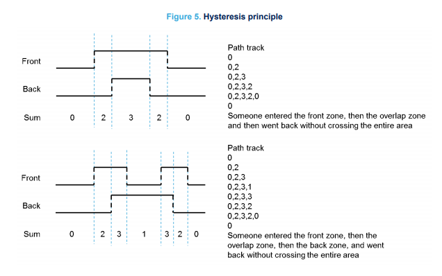
The algorithm validates a crossing event only when a person has fully crossed the two zones. It does not validate the
event when the person remains for a long time under the FoV or when the person decides to return from the place he
came from.
This is illustrated in the figure below: the algorithm stops and the list of states is reset as soon as no-one is detected in
any of the two FoVs.
6.1.3 Hysteresis
6.1.4 Ranging on the floor to determine the threshold

Reliability of the algorithm relies on the accuracy of the setup which detects the distance between the sensor and the
floor. This can be ensured only if nothing (e.g. no obstacle or static object) blocks the front and back FoVs. To assess if
a setup is reliable, a significant number of distances can be measured with the sensor. Then, a histogram diagram can
be established to confirm that the sensor is correctly set up and that no target is within its FoVs.
A threshold needs to be defined, which is achieved after having ranged on the flooring material over a significant
number of samples. In fact, the threshold should be chosen so that all the measured distances (when ranging the floor)
are greater than this threshold. We recommend that at installation of the application, an autocalibration routine is
launched to calculate the threshold. This is because flooring material can be different in many locations.
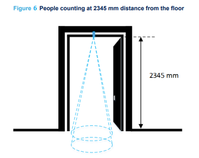
Figure 6. People counting at 2345 mm distance from the floor. The distance between the sensor and the floor is 2345
mm, and as the minimum distance measured by the sensor is 2290 mm, the threshold is thus less than 2290 mm.
Note: This calibration should be performed in the worst ambient light conditions, to maximize the jitter and obtain a
threshold that is relevant to all possible ambient lighting conditions the counting setup is exposed to.
Hi-Byte is error code
Error code
Description
0
No error
1
Just exchange the sensor module but node has not been reset ==>
please take out the battery for 20s then install it again to reset node to
recognize the new sensor module
2
Error, sensor port M12F shorted to GND
3
Error, sensor port M12F shorted to Vcc
4
Error, sensor port M12F shorted each other
Lo-Byte is sensor type
Error code
Description
0
No error
1
Just exchange the sensor module but node has not been reset ==>
please take out the battery for 20s then install it again to reset node to
recognize the new sensor module
2
Error, sensor port M12F shorted to GND
3
Error, sensor port M12F shorted to Vcc
4
Error, sensor port M12F shorted each other
6.2 Status bytes of sensor Node
6.3 Add sensors node to Co-ordinator WS433-CL
Step 1: After supplying power the Co-ordinator via M12 connector, the Node ID must be registered within the first 5
minutes, up to 40 WS.
Step 2: Bring the wireless sensor closer to the Co-ordinator's antenna then take off the wireless sensor battery, wait
for 5s then insert the battery again. If:
Buzzer plays 1 peep sound, LED blink 1 time, that means registering Node ID on Co-ordinator successfully.
Buzzer plays 2 peep sounds, LED blink 2 times, that this Node ID is already registered.
Node id added in this way will be written to the smallest node_id_n address which is = 0.
Set Rssi_threshold (see RF MODE CONFIG (in the Modbus Memmap of WS433-CL), default -25): The case if Co-
ordinator is on high position and need to add node sensor. We set the sensor as close as possible and set the
Rssi_threshold to -80, -90 or -100 to increase the sensitivity to allow WS433-CL-04 can add sensors at a longer
distance. After that, perform 2 steps of adding sensors and then reset Rssi_threshold = -25.
Enb_auto_add_sensors configuration (see RF MODE CONFIG (in the Modbus Memmap of WS433-CL)): In case
you do not want to turn off the power WS433-CL, you can set Enb_auto_add_sensors = 1, this way we have 5
minutes to add nodes (add up to 40 nodes) . After 5 minutes Enb_auto_add_sensors will automatically = 0.
http://www.daviteq.com/en/manuals/books/long-range-wireless-co-ordinator-ws433-cl/page/user-guide-
for-long-range-wireless-co-ordinator-ws433-cl
First, you need to prepare
6.3.1 Add Sensor Node ID automatically
If you do not hear the "Peep" sound, please disconnect the power the co-ordinator, wait a few minute and try
again.
Memmap resgisters
You can download Modbus Memmap of WS433-CL with the following link:
https://filerun.daviteq.com/wl/?id=BKEaUzdArkoc0Hc7nfpRShdPVToVrqQZ
6.3.2 Add sensor node into WS433-CL-04 (1) through intermediate
WS433-CL-04 (2) and Modbus
In case the sensor need to be added to WS433-CL-04 (1) has been installed in a high position, the
sensor cannot be brought close to WS433-CL-04 (1). For more details:
6.4 Configuration

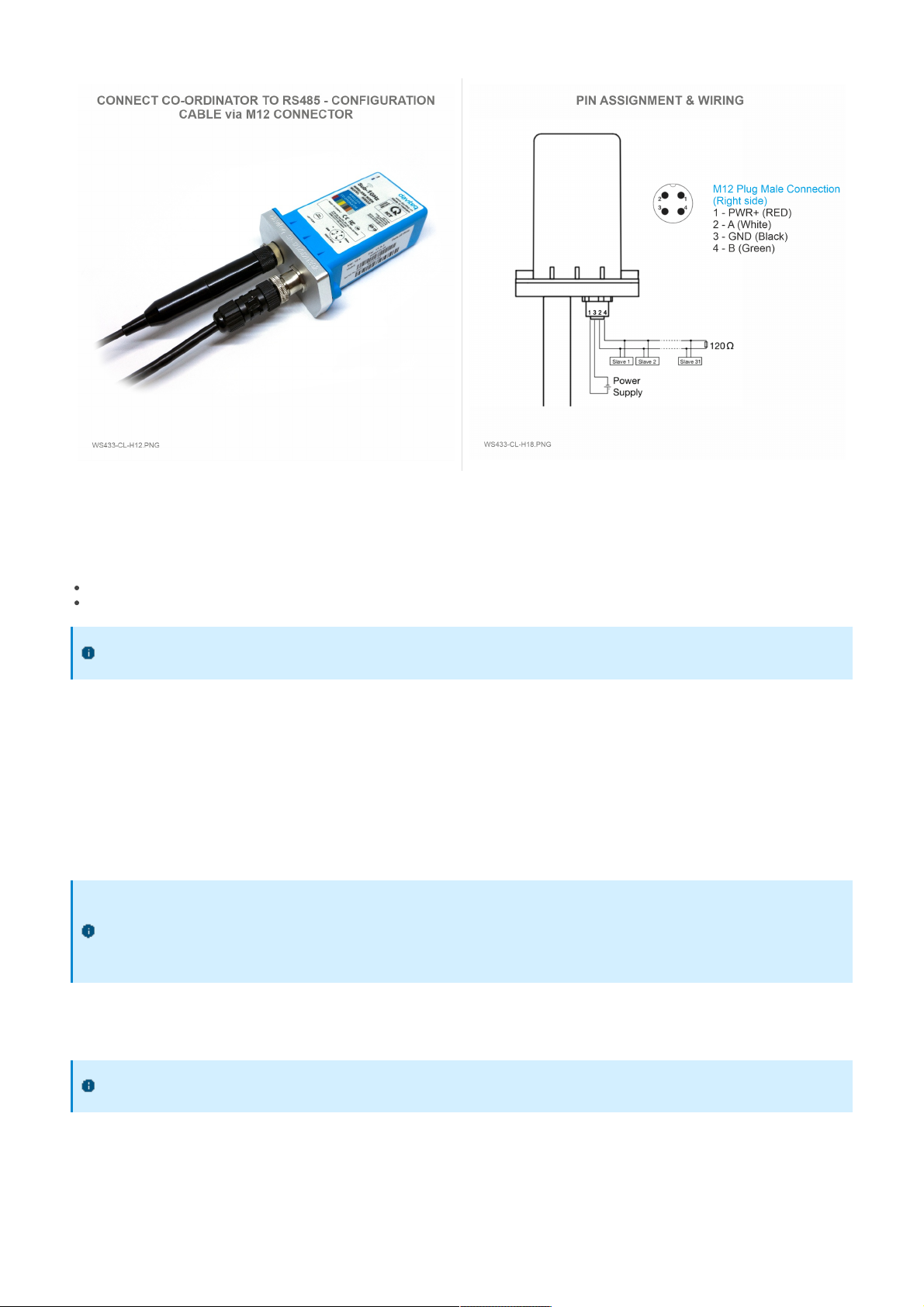
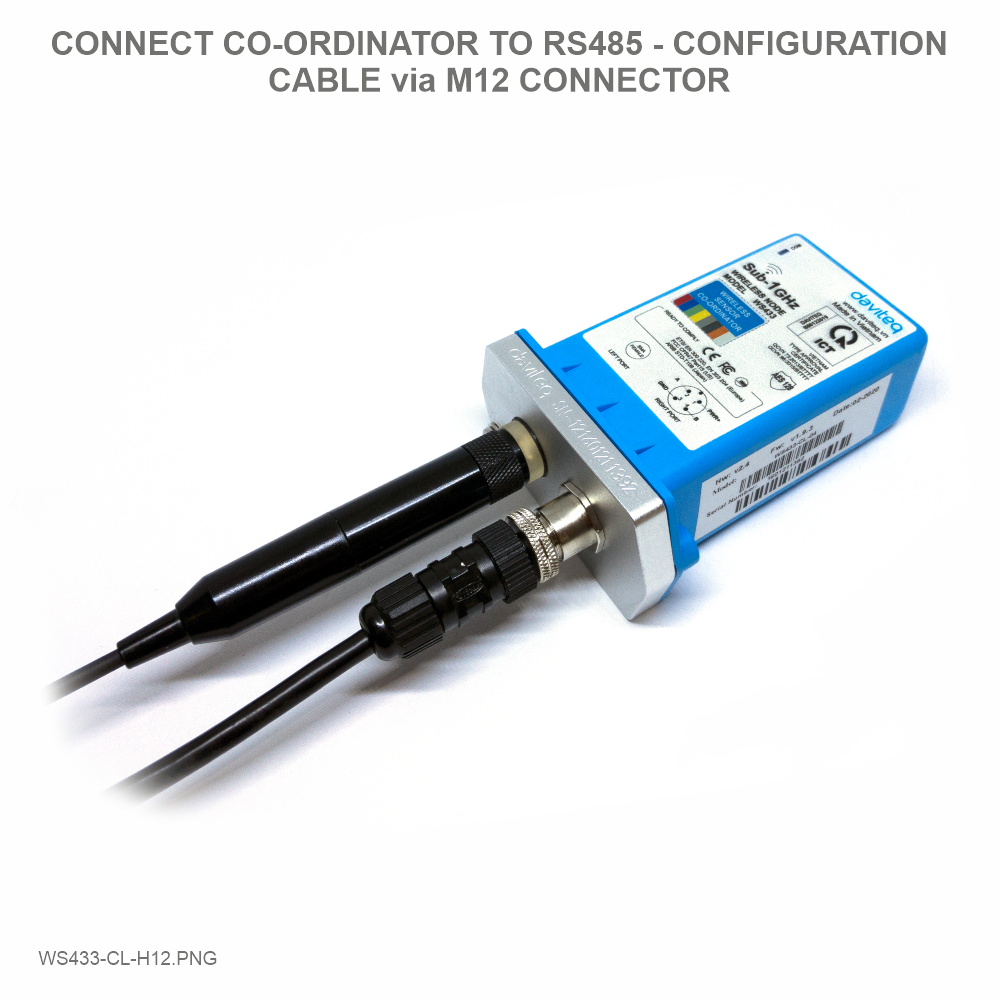
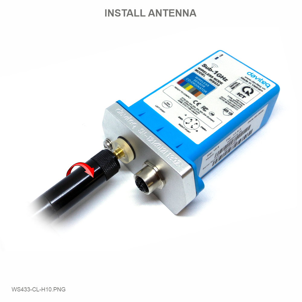
Step 1: Connect Antenna, RS485 - configuration cable and power supply co-ordinator
Num of Node will indicate the number of nodes managed by WS433-CL.
Every time a node is added, the Num of Node will increase by 1.
Every time a node is deleted, the Num of Node is reduced by 1.
Writing Num of Node = 0 will delete all 40 node ids to 0.
If you want to delete a node id, then write it = 0 with the Write function is 16 and the Read function is 3.
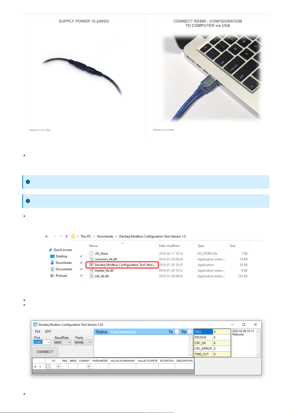
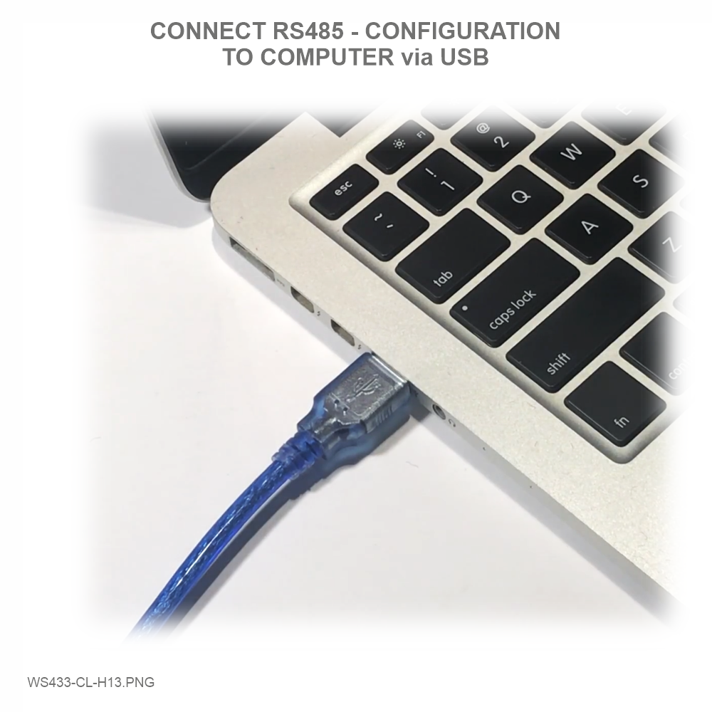
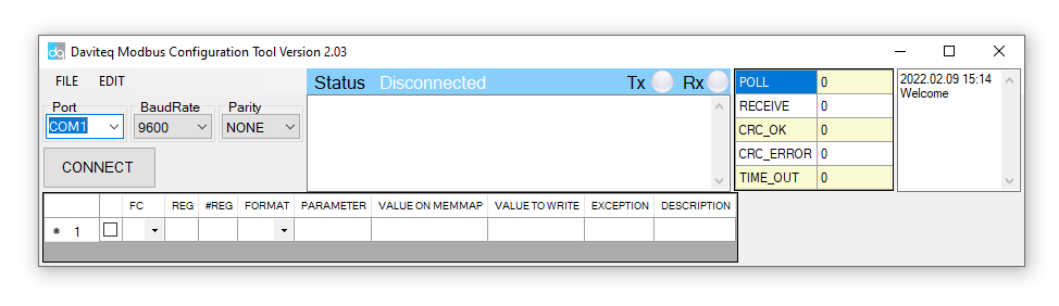
Step 2: Open Modbus tool on PC
You can download Daviteq Modbus Configuration Tool with the following link:
https://filerun.daviteq.com/wl/?id=yDOjE5d6kqFlGNVVlMdFg19Aad6aw0Hs
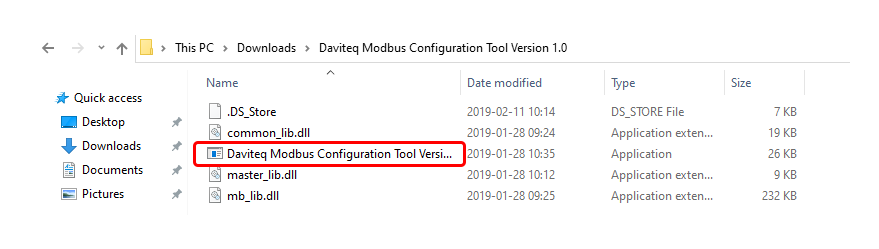
Unzip file and run file application "Daviteq Modbus Configuration Tool Version"
Choose COM Port (the Port which is USB cable plugged in)
Set the BaudRate: 9600, Parity: none
Click “ Connect “ untill the Status displays “disconnected” to “connected“. It means the WS433-CL-04 is
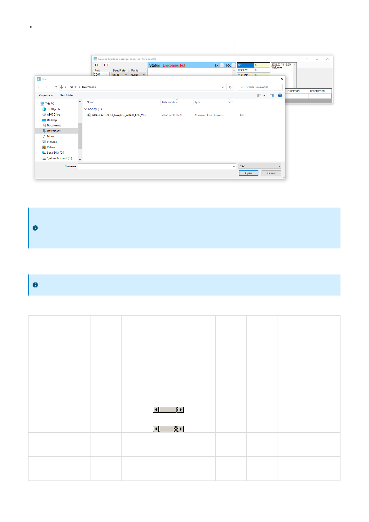
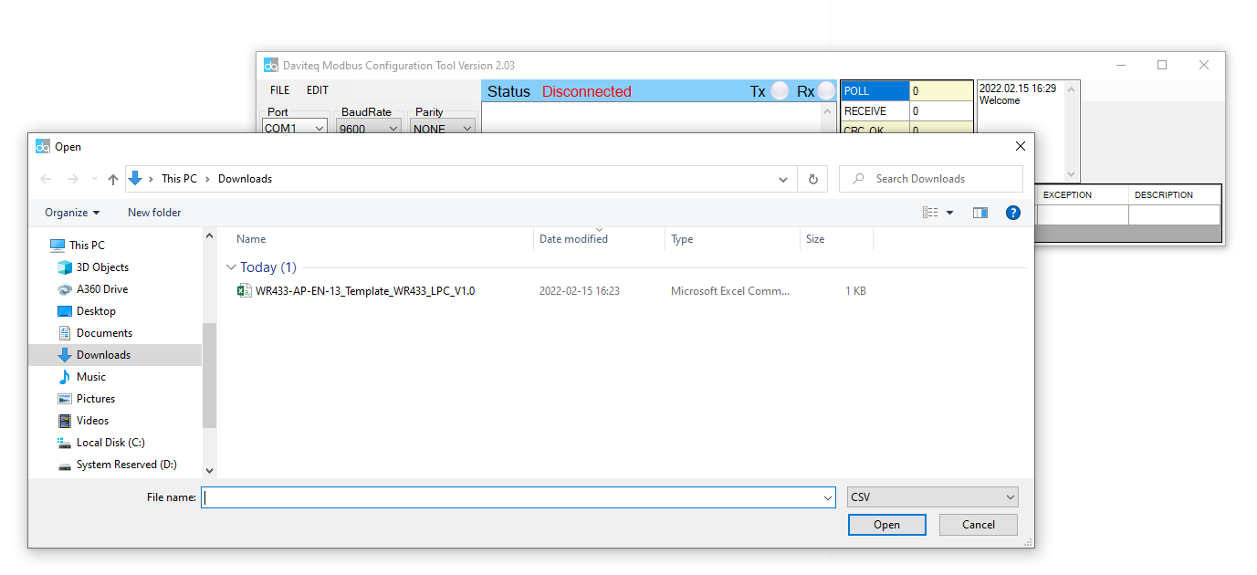
Template File: https://filerun.daviteq.com/wl/?id=xYEknMN8AhRLTmf73fXh9SWf0Ryp1QMa
How to use the Modbus configuration software
being connected with computer;
Next, we need to import the configuration file for WS433-CL-04 by importing the csv file: Go to MENU: FILE /
Import New / => select the template file.
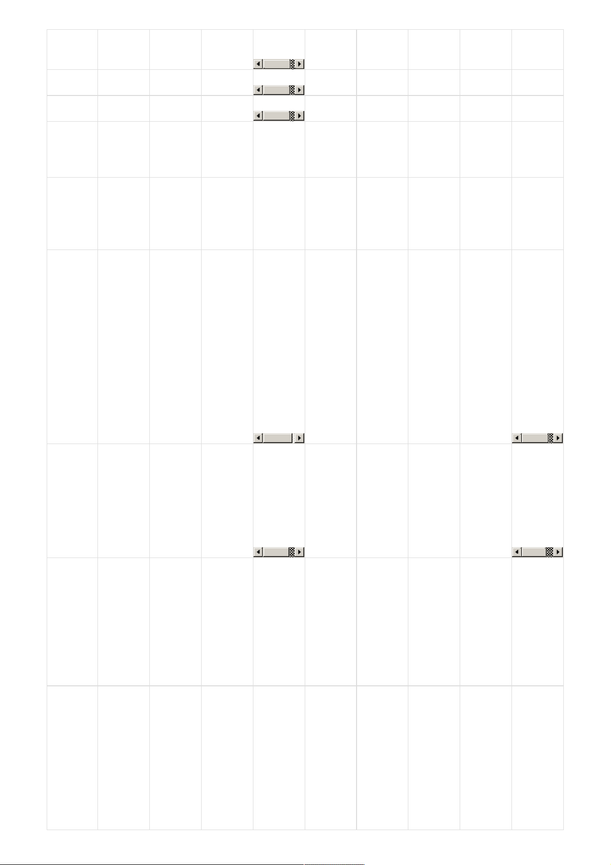
Step 3: Configure parameters of the sensor.
In the memmap file, refer to the Memmap of WS433-LPC sheet to configure the sensor's operating parameters
accordingly.
Typical sensor parameters:
Function
Code
(Read)
Function
Code
(Write)
# of
register
Byte Size
Description
Value
Range
Default
Format
Property
Explanation
4
1
2
%Battery
of sensor
Node
10,30,60,99
uint16
Read
Battery
level, only
04 levels:
10%, 30%,
60% and
99% (full).
When 10%
==> Need
to replace
the battery
4
1
2
NRC_People_In
uint16
Read
Non-
resettable
counter
4
1
2
NRC_People_Out
uint16
Read
Non-
resettable
counter
4
1
2
Status
bytes of
sensor
Node
uint16
Read
Hi-Byte is
error code,
Lo-Byte is
sensor type
4
1
2
RC_People_In
uint16
Read
Reset to 0
after
sending to
Coordinator
Memmap resgisters
You can download Modbus Memmap of WS433-CL with the following link:
https://filerun.daviteq.com/wl/?id=BKEaUzdArkoc0Hc7nfpRShdPVToVrqQZ
The reference memmap addresses are based on the order of the sensors added in the Memmap file
above
4
1
2
RC_People_Out
uint16
Read
Reset to 0
after
sending to
Coordinator
4
1
2
Dist_front_zone
int16
Read
Distance of
front zone
4
1
2
Dist_back_zone
int16
Read
Distance of
back zone
3
1
2
Data status
of Node
0-9, 99
byte
Read
0-9:
Interval
updated
data
99:
Disconnected
3
1
2
RF Signal
strength of
Node
0-4
byte
Read
From 0 to 4
with 0 is
being lost
connection
RF and 4 is
the
strongest
RF
3
16
1
2
Cycle_wakeup
1-3600(s)
120
uint16
Read /
Write
Every time
interval of
Cycle_wakeup,
sensor node
would ONLY
send data
to co-
ordinator if
the new
measured
value was
changed
more than
the Delta
value of the
last
measured
value.
Default
Cycle_wakeup
is 120
seconds
3
16
1
2
Cycle_healthsta
60-7200(s)
600
uint16
Read /
Write
Every time
interval of
Cycle_healthsta,
sensor node
will
absolutely
send data
to co-
ordinator
regardless
any
condition
3
16
2
4
Co-
ordinator id
0
uint32
Read /
Write
Configure
the ID
number of
Co-
ordinator
that
wireless
sensor want
to connect
to the Co-
ordinator
when only
adding the
sensor
manually
3
16
2
4
Radio
frequency
433.05-
434.79, 433
Mhz
433.92
float
Read /
Write
Configure
the
operating
frequency
of wireless
sensor by
Co-
ordinator,
should be
configured
from
433.05-
434.79
MHz, only
for
advanced
users

3
16
1
2
Tx power
-10,10,15
15
int16
Read /
Write
Configure
the RF
power of
wireless
sensor by
Co-
ordinator,
only for
advanced
users
+ 15 <=>
tx power =
15dBm
+ 10 <=>
tx power =
10dBm
+ -10 <=>
tx power =
-10dBm
3
16
1
2
Data rate
RF
0-1
0
uint16
Read /
Write
Configure
the air data
rate of
wireless
sensor by
Co-
ordinator,
only for
advanced
users
+ 0 <=>
data rate
RF at
50kbps
+ 1 <=>
data rate
RF at
625bps
3
16
1
2
Count_threshold
20
uint16
Read /
Write
Threshold
count on
how many
people send
Coordinator
3
16
1
2
Dist_threshold
1600
uint16
Read /
Write
Threshold
setting for
laser sensor
to
distinguish
between
when
people are
present and
when no
one is
standing
under the
sensor
The laser
sensor will
measure
the
distance
value from
the sensor
(ceiling) to
the floor.
+ When
there are
people, the
measured
laser sensor
value <
Dist_threshold
+ When
there is no
person, the
measured
laser sensor
value >
Dist_threshold
3
16
1
2
Dist_hys
100
uint16
Read /
Write
Hysteresis
of
Dist_threshold
3
16
1
2
Inter_meas_period
48
uint16
Read /
Write
The
sampling
time of the
sensor laser
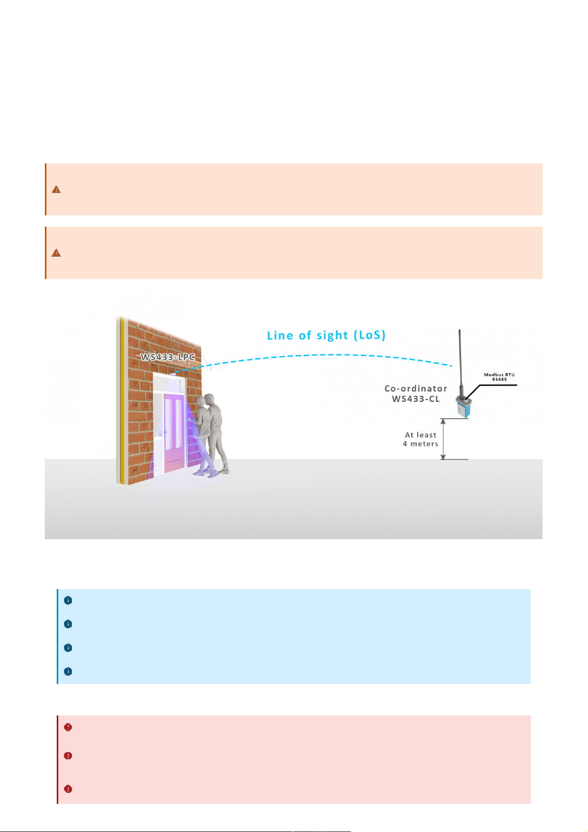
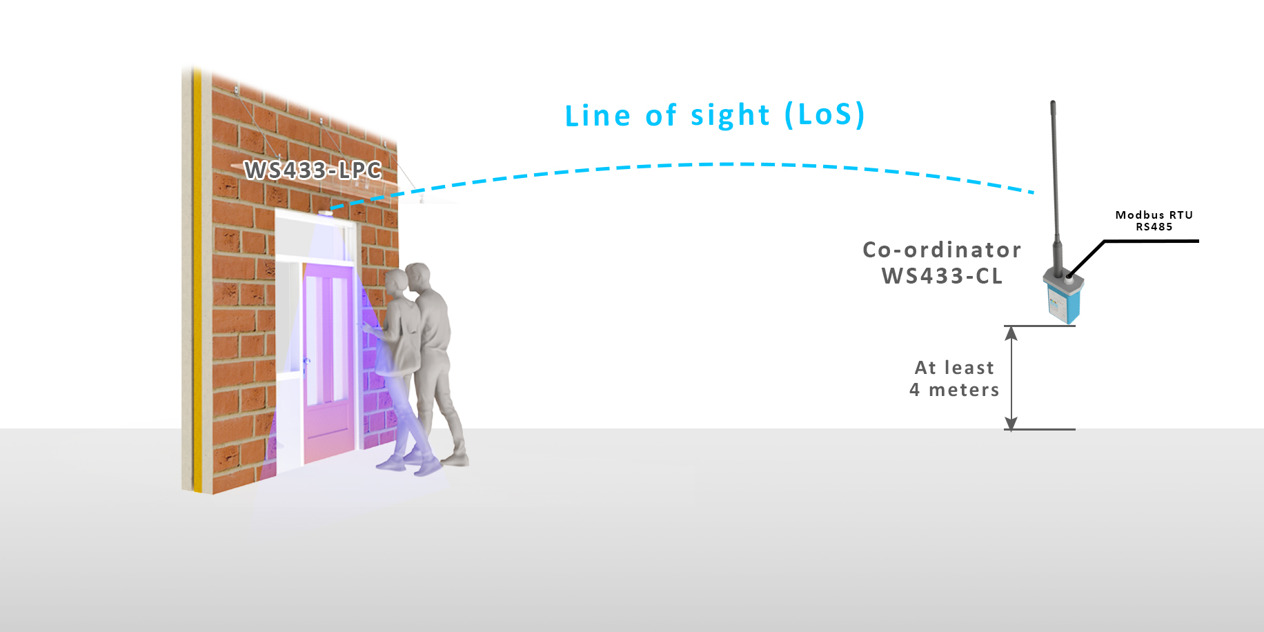
Wireless sensor utilize the ultra-low power 433Mhz RF signal to transmit/receive data with Wireless co-ordinator.
To maximize the distance of transmission, the ideal condition is Line-of-sight (LOS) between the Wireless sensor and
Gateway. In real life, there may be no LOS condition. However, the two modules still communicate each other, but the
distance will be reduced significantly.
7. Installation
7.1 Installation location
ATTENTION:
DO NOT cover the Wireless sensor or its antenna inside a completed metallic box or housing, because the RF
signal can not pass through the metallic material.
NOTE:
Integrated WS433-CL / iConnector Coordinator The coordinator must be placed at least 4 meters above the
ground and the WS433-LPC clearly visible.
7.2 Mounting
Installation method: Mount to the ceiling
Locate the mounting position at the entrance where people pass by, and out of direct sunlight
The direction of the triangle is the direction of counting people entering as specified in the payload
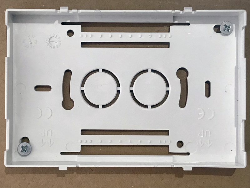
Determine the correct orientation to install the bottom cover to the ceiling in the correct direction
WARNING:
Avoid placing hands or heavy objects on the laser sensor surface or the PIR sensor surface, as this may
cause damage to the device;
Periodically use a clean cloth moistened with 70 degrees of alcohol to wipe the surface of the 2 sensors to
keep the sensor clean and accurate.
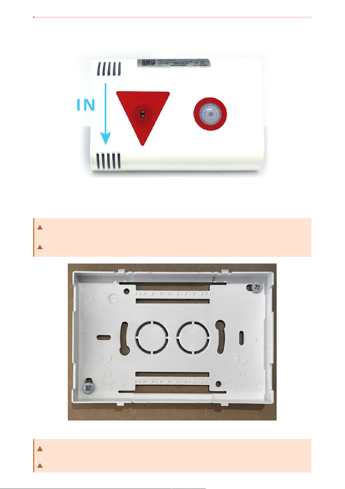
Step 1: Determine the direction of people entering the room of the sensor
Step 2: Mount the bottom housing of the sensor to the ceiling by fasten the 2 screws to the ceiling located at the 2
diagonal corners of the bottom cover.
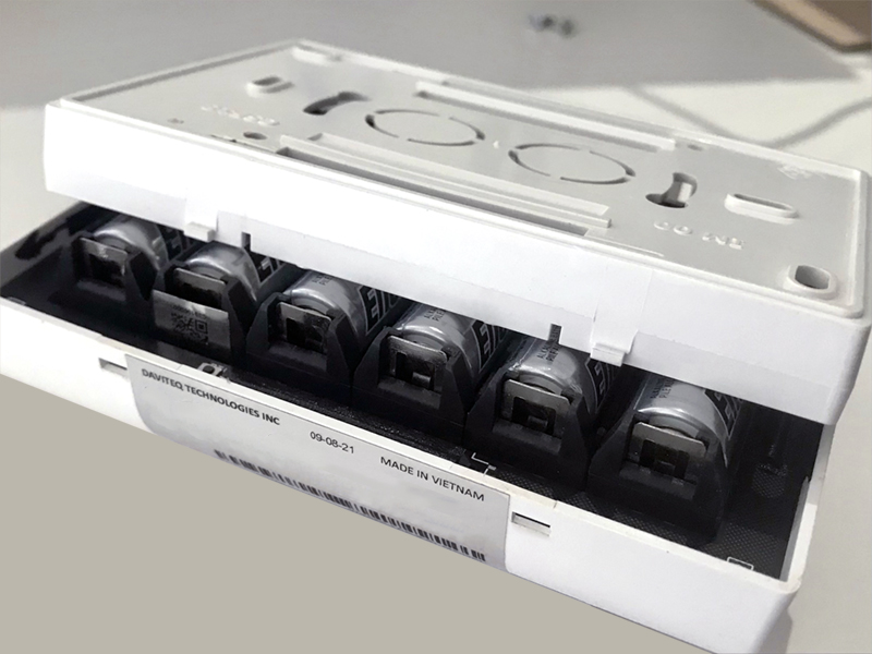
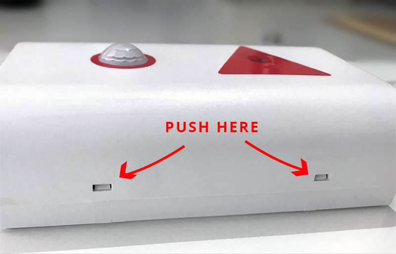
Step 3: Attach the top and bottom housings (note the 2 reed joint)
Use the 2 screws that are included to be used to attach the sensor to surfaces such as: Wood, composite
plastic.
If the ceiling surface is made of plaster, it is recommended to use a special insert so that the device can
firmly adhere to the ceiling surface. Avoid dropping the device.
Fit the main body to the bottom cover in the correct direction: the 2 reed joints on the bottom cover
should fit into the main body on the side labeled with the device.
Make sure that the main body is fully engaged with the bottom cover, then release the hand.


No.
Phenomena
Reason
Solutions
1
The status LED of wireless sensor
doesn't light up
No power supply
Configuration function of
the LED is not correct
Check that the battery is
empty or not installed
correctly
Reconfigure the led light
function exactly as
instructed
2
Wireless sensor not connected to
co-ordinator
No power supply
The configuration function
of the RF data rate is
incorrect
Check that the battery is
empty or not installed
correctly
Reconfigure the RF data
rate with the button
according to the
instructions
Manufacturer
Daviteq Technologies Inc
No.11 Street 2G, Nam Hung Vuong Res., An Lac Ward, Binh Tan Dist., Ho
Chi Minh City, Vietnam.
Tel: +84-28-6268.2523/4 (ext.122)
Email: info@daviteq.com | www.daviteq.com
Distributor in Australia and New Zealand
Templogger Pty Ltd
Tel: 1800 LOGGER
Email: contact@templogger.net
Revision #4
Created Tue, Feb 15, 2022 3:57 AM by Kiệt Anh Nguyễn
Updated Tue, Feb 15, 2022 9:53 AM by Kiệt Anh Nguyễn
7. Troubleshooting
8. Support contacts
This manual suits for next models
1
Table of contents
Other daviteq Cash Counter manuals


