Allsafetyrelatedcodifications,symbolsandinstructionsthatappearinthisoperatingmanual
orontheequipmentmustbestrictlyfollowedtoensurethesafetyoftheoperatingpersonnelas
wellastheinstrument.
Ifalltheequipmentisnothandledinamannerspecifiedbythemanufacturer,itmightimpairthe
protectionprovidedbytheequipment.
Productimprovementandupgradeisaconstantprocedure.Soformoreupdatedoperatinginformationandsupport,
Pleasecontactourhelpline:+91-9978991474/76/82orEmailat
[email protected]Ver:04-2018
=> Readcompleteinstructionspriortoinstallationandoperationoftheunit.
WARNING: Riskofelectricshock.
3)Cableusedforconnectiontopowersource,musthaveacrosssectionof1mmorgreater.Thesewires
shouldhaveinsulationscapacitymadeofatleast1.5kV.
2)Toreduceelectromagneticinterference,usewirewithadequateratingandtwistsofthesameofequalsizeshall
bemadewithshortestconnection.
4)Whenextendingthethermocoupleleadwires,alwaysusethermocouplecompensationwiresforwiringfortheRTD
type,useawiringmaterialwithasmallleadresistance(5maxperline)andnoresistancedifferentialsamong
threewiresshouldbepresent.
1)TopreventtheriskofelectricshockpowersupplytotheequipmentmustbekeptOFFwhiledoingthewiring
arrangement.Donottouchtheterminalswhilepowerisbeingsupplied.
5)Abetteranti-noiseeffectcanbeexpectedbyusingstandardpowersupplycablefortheinstrument.
1)Thisequipment,beingbuilt-in-type,normallybecomesapartofmaincontrolpanelandsuchincasethe
terminalsdonotremainaccessibletotheenduserafterinstallationandinternalwiring.
2)Donotallowpiecesofmetal,wireclippings,orfinemetallicfillingsfrominstallationtoentertheproduct
orelseitmayleadtoasafetyhazardthatmayinturnendangerlifeorcauseelectricalshocktotheoperator.
3)Circuitbreakerormainsswitchmustbeinstalledbetweenpowersourceandsupplyterminalto
facilitatepowerONorOFFfunction.Howeverthismainsswitchorcircuitbreakermustbe
installedatconvenientplacenormallyaccessibletotheoperator.
4)Useandstoretheinstrumentwithinthespecifiedambienttemperatureandhumidityrangesas
mentionedinthismanual.
WarningGuidelines
SafetyPrecautions
InstallationGuidelines
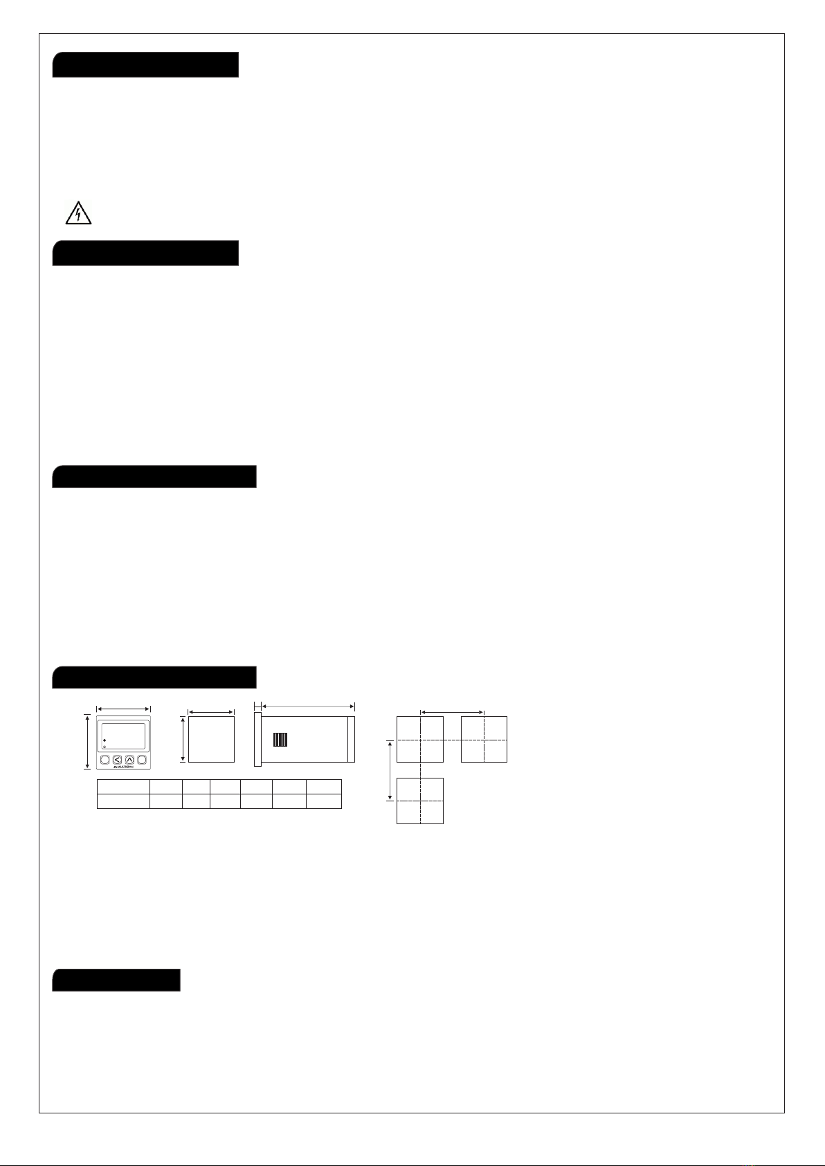
MechanicalInstallation
Maintenance
1)Preparethepanelcutoutwithproperdimensionsasshowabove.
2)Fittheunitintothepanelwiththehelpofclampgiven.
3)Theequipmentinitsinstalledstatemustnotcomeincloseproximitytoanyheatingsource,
causticvapors,oilssteam,orotherunwantedprocessbyproducts.
4)Usethespecifiedsizeofcrimpterminal(M3.5screws)towiretheterminalblock.Tighteningthe
screwsontheterminalblockusingthetighteningtorqueoftherangeof1.2N.m.
5)Donotconnectanythingtounusedterminals.
1)Theequipmentshouldbecleanedregularlytoavoidblockageofventilatingparts.
2)Cleantheequipmentwithacleansoftcloth.Donotuseisopropylalcoholoranyothercleaningagent.
3)Fusibleresistormustnotbereplacedbyoperator.
2
www.multispanindia.com
Page-4PC-444
A
B
C
D
EF
MODEL A
48mm 48mm 44mm 44mm 3mm 95mm
BC
D E
F
DIMENSIONS
68mm-2.68inches
60mm-2.36inches
RESET
SET
ENT
PC 444
SET COUNT
COUNT
R1
R2
.
.