Dawnway HT400 User manual

HT400&DF3600,DF5050
LEAD FREE
DIGITAL INSTANT HOT WATER DISPENSER
HT400&DF3601,DF5051
LEAD FREE
DIGITAL INSTANT HOT AND COLD WATER DISPENSER
INSTALLATION MANUAL
DF3600
DF3601
DF5050 DF5051
HT400
Digital Instant Hot Water Dispenser Instruction Ver. A-E 2022/12/1

IMPORTANT INFORMATION
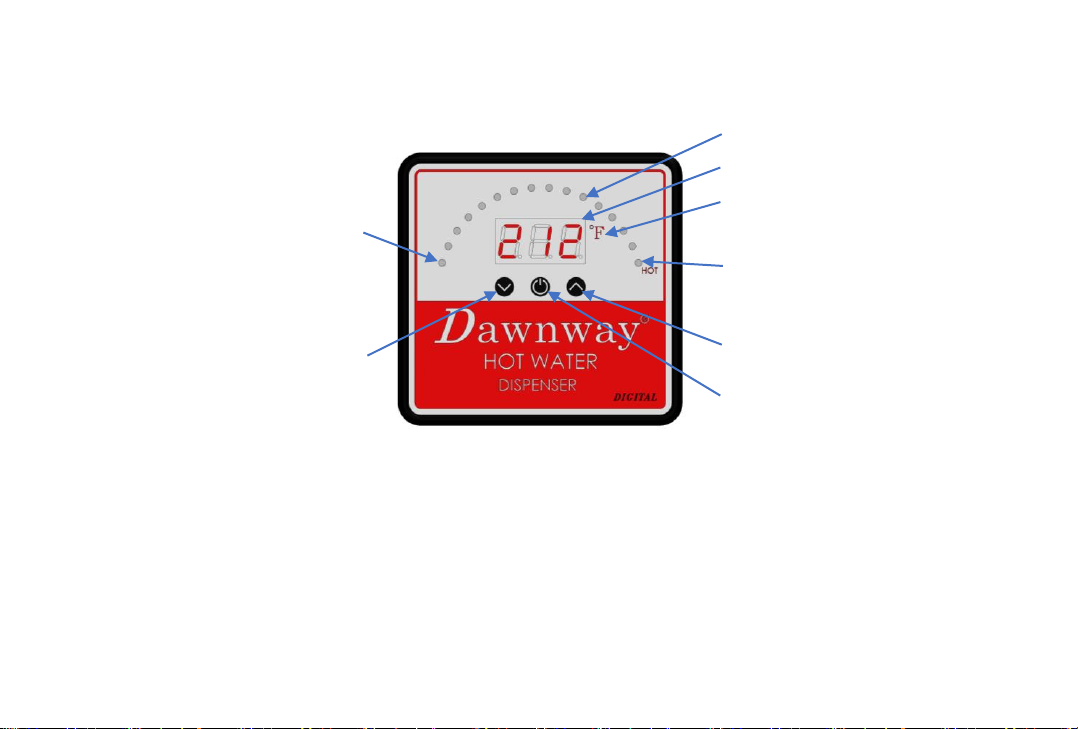
This digital hot water dispenser produces instant hot
water of approximately100゚C (212゚F, max.) as
dispensed from the faucet.
This product is not intended to produce a continuous
flow of hot water.
The standard model will produce up to 60 cups of
water per hour at approximately 88゚C (190゚F ). Due to
high water temperature, for safety reasons, the tank is
not under pressure. Consequently, there is a slight
delay of water flow after the faucet has been activated.
This is normal and indicates that the expansion
chamber is functioning properly.
This appliance is not intended for use by persons
(including children) with reduced physical, sensory or
mental capabilities, or lack of experience and
knowledge, unless they have been given supervision or
instruction concerning use of the appliance by a person
responsible for their safety. Children should be
supervised to ensure that they do not play with the
appliance.
1
IMPORTANT SAFETY INSTRUCTIONS
PLEASE READ ALL INSTRUCTIONS VERY CAREFULY
1. Read all instructions.
2. To protect against electrical shock, do not place cord,
plugs, or appliance in water or other liquid.
3. Do not operate any appliance with a damaged cord
or plug, or after the appliance malfunctions. Return
appliance to the factory for examination, repair or
adjustment. See Warranty insert.
4. Do not use outdoors or in damp area.
5. Do not let cord hang over edge of table or counter,
or touch hot surfaces.
6. Do not use appliance for other than intended
household use.
7. Do not attempt to service this product. Repairs
should be done by authorized service personnel.
8. Do not let children operate. The water can cause
severe burns.
When using electrical appliances, basic safety
precautions should always be followed including the
following:

SAVE THESE INSTRUCTIONS. THIS PRODUCT
FOR HOUSEHOLD USE ONLY.
The alert symbols displayed above point to important
safety information to make you aware of potential
hazards that can cause serious injury or death. Please
pay special attention to the information following these
alerts and warnings. Failure to comply with these
instructions can result in property damage, serious
injury of death.
ELECTRICAL SUPPLY
THIS APPLIANCE MUST BE EARTHED, In the event of a
malfunction, earthing provides a path of least
resistance for the electrical current, thus reducing the
risk of electrical shock.
This dispenser is rated 120VATTS , 50/60 Hz , maximum
10.9AMPS and should be connected to a main
distribution board or consumer unit.
Before you begin connecting the electrical supply, you
should be thoroughly familiar with electrical power and
procedures. If you are not, consult an electrician.
IS THE DISPENSER EARTHED?
THIS APPLIANCE MUST BE EARTHED.
In the event of malfunction or breakdown, earthing
reduces the risk of shock. This dispenser must be
connected to an earthed, metal, permanent wiring
conductor and connected to the equipment earthing
terminal or lead on the dispenser.
HOT WATER CONCEPT
Unlike a household water heater, this dispenser tank is
not pressurized for safety reasons. For a conventional
household water heater, the faucet valve is placed after
the heater tank resulting in a pressurized tank. For a
hot water dispenser, the faucet valve is placed before
the tank, creating an "open vent" style faucet and
consequently no pressure is built up inside the tank.
Operating inlet water pressure requirements :
172kPa (1.7bar, 25psi) Min and 861 kPa (8.6bar, 125psi)
Max
2

HT400
DIGITAL INSTANT HOT WATER DISPENSER
SPECIFICATION SHEET
. 2.3 LITTER STAINLESS STEEL TANK
. ALL STAINLESS STEEL TANK AND CASE
. 1 YEAR WARRANTY TO ORIGINAL PURCHASER
. MOUNTING BRACKET INCLUDED
ELECTRICAL SPECIFICTION
. 120 VAC, 50/60Hz
750 WATTS, 6.3 AMPS
1000 WATTS, 8.4 AMPS
1300 WATTS, 10.9 AMPS
. MAX TEMP 100 ℃(212 ℉) UNIT : [INCH]
mm
3
quick-connect fitting
with filter and cap
quick-connect fitting
accessory :
Inlet pipe
outlet pipe

DF3600
LEAD FREE FAUCET
INSTANT HOT WATER DISPENSER
SPECIFICATION SHEET
4
UNIT : [INCH]
mm
MOUNTING
HOLE
The green labeled pipe
connects with water
supply.
Silicon tube connects
with the outlet pipe
of tank.
The red
labeled pipe
connects
with the inlet
tube of tank.

DF5050
LEAD FREE FAUCET
INSTANT HOT WATER DISPENSER
SPECIFICATION SHEET
5
UNIT : [INCH]
mm
MOUNTING
HOLE
The green
labeled pipe
connects
with water
supply.
Silicon tube
connect with the
outlet pipe of
tank.
The red
labeled pipe
connects
with the inlet
tube of tank.

DF3601
LEAD FREE FAUCET
INSTANT HOT AND COLD WATER DISPENSER
SPECIFICATION SHEET
HOT WATER
LINE
COLD WATER
LINE
6
UNIT : [INCH]
mm
MOUNTING
HOLE
The green
labeled pipe
connects
with water
supply.
Silicon tube
connect
with the
outlet pipe
of tank.
The red
labeled pipe
connects
with the inlet
tube of tank.
The blue labeled
pipe connects
with cold water
supply.

DF5051
LEAD FREE FAUCET
INSTANT HOT AND WATER DISPENSER
SPECIFICATION SHEET
7
UNIT : [INCH]
mm
HOT WATER
LINE
COLD WATER
LINE
MOUNTING
HOLE
The green
labeled pipe
connects
with water
supply.
Silicon tube
connect
with the
outlet pipe
of tank.
The red
labeled pipe
connects
with the inlet
tube of tank.
The blue labeled
pipe connects
with cold water
supply.

8
Cold water inlet supply line
feeds through faucet then to
tank via the connection at the
rear corner on the top of the
hot water dispenser.
Make sure countertop has a
1 1/4” to 1 3/8” (32mm or
35mm) mounting hole.
1 3/8”(35mm) maximum
countertop thickness.
Quick-connect fitting
with filter and cap
connects to cold water
supply line filter and
cap side points toward
faucet.
Center outlet sends hot
water to dispenser when
faucet is turned on.
Approximately 36”(914mm) electrical outlet to tank
CAUTION : Tank must
be mounted in the
vertical position.
Before switching on the
heater, ensure water
flows from faucet.
OVERVIEW OF A COMPLETED SET-UP
Shut-off valve

CONTROL PANEL
You will be instructed throughout this document to learn a method of operating digital water heater. Please refer to the
diagram below to understand variety functions.
INSTRUCTIONS
1. The current temperature represents the current temperature of water inside the tank.
2. The target temperature represents that the water inside the tank will be heated up to this temperature.
3. The heating temperature represents that a temperature is 3 ℃(5 ℉) lower than the target temperature. The water heater will
start working if the current temperature is lower.
4. After connecting to the power source, the indicating lights(1) will flash on from the leftmost LED(7) to the rightmost LED(4)
sequentially and then light off all and repeat both three times. The temperature indicator(2) shows the current temperature.
As the indicating lights(1) light off all, the water heater won’t work.
5. Indicating lights(1) illustrate the current temperature or the water heater is working or not and auto running mode is on or off.
Each LED represents 5 ℃(9 ℉).
9
(1)Indicating Lights(16 LEDs)
(2)The temperature Indicator
(3)The unit of temperature
(5)The button of rising
target temperature
(8)The button of
reducing target temperature
(6)The button of auto running
(4)The rightmost LED indicates the
water temperature of the tank being
higher than 95℃(203℉)
(7)The leftmost LED Indicates the
water temperature inside the tank
being lower than 25℃(77℉)

OPERATING INSTRUCTION
1. Setting the target temperature
. Pressing and then releasing the button of rising target temperature(5), the temperature indicator(2) changes to show the target
temperature and the target temperature rises up 1 ℃(2~3℉) as it is higher then 90 ℃(194℉); otherwise, it rises up 5 ℃(9℉) each time.
The highest target temperature is 100 ℃(212℉).
. Pressing and holding on the button of rising target temperature(5), the target temperature will rise continually until releasing it,
After releasing it and waiting for 3 secs, the temperature indicator(2) will return to show the current temperature.
. Pressing and then releasing the button of reducing target temperature(8), the temperature indicator(2) changes to show the target
temperature and the target temperature reduces 1 ℃(2~3℉) as it is higher then 90 ℃(194℉); otherwise, it reduces 5 ℃(9℉) each time.
The lowest target temperature is 25℃(77℉).
. Pressing and holding on the button of reducing target temperature(8), the target temperature will reduce continually until releasing
it, After releasing it and waiting for 3 secs, the temperature indicator(2) will return to show the current temperature.
2. Auto running mode
. Auto running mode means that if the current temperature is lower then the heating temperature, the water heater will start
working and if the current temperature is equal to the target temperature, the water heater stops working.
. As the indicating lights(1) light off all, the water heater won’t work. It is not on auto running mode.
. Pressing and then releasing the button of auto running(6), the water heater goes into the auto running mode. Repressing and
releasing it, the water heater will turn off the auto running mode. Alternately pressing and releasing the button of auto running(6) could
change the state of the water heater.
. When the water heater goes into the auto running mode, indicating lights(1) light on from the leftmost LED(7) to the LED of
compared to the current temperature continuously.
. When the water heater is working, the indicating lights(1) light on from the leftmost LED(7) to the LED of compared to the current
temperature sequentially and then light off all and will repeat until the water heater stops working.
3. Reheating function
. To Use this function, the water heater must be in the auto running mode.
. As the current temperature is between the target and heating temperature, the water heater won’t work. If you want to get higher
temperature soon. You can long press the button of auto running(6) for 3 secs, the water heater will start working immediately.
10

11
BEFORE YOU BEGIN INSTALLATION
1. Before connecting to the power source, the tank must be filled with water.
2. Do not use an extension cord with this appliance. Appliance must be within approximately 36" (914 mm) of the power
source.
3. Do not use any pipe sealing compounds as they may get inside the dispenser causing a discomforting taste and odor.
4. Determine a convenient location to mount faucet and tank. Important considerations when determining location
include:
•Installation must comply with local plumbing codes.
•Read these instructions for the dispenser and heating tank before proceeding.
•Dispenser will drip occasionally in use after water is drawn and tank is heating more water. This is normal.
•Make sure the tank outlet supply tube has no loops or low areas.
•Tighten fitting with an adjustable crescent or open wrench. Never use a pipe wrench.
•Never dispense both hot and cold water at the same time.
•Dispenser will occasional drip and spurt during water boiling. Lower target temperature to prevent spurting.
•Be sure faucet is positioned where there will be no contact with the water flow when turning the faucet on and off to
avoid burns.
•Be sure to allow for 4" to 6" (102 mm to 154 mm) of space around the front and sides of the tank to allow for air
circulation.
•The container(s) you will use with the appliance such as a large cooking pan or carafe.

5. Mounting Hole Size Requirements :
•Existing hole in sink (the spray hose opening for example) or drilling another hole into the sink or countertop, You will need a 1
1/4“ (32 mm) or 1 3/8” (35 mm) hole in your sink.
•Drilling into a stainless steel sink : You need a 1 ¼” (32 mm) or 1 3/8" (35 mm) knockout punch (available at most hardware stores)
or drill a hole with an expandable drill.
•Drilling into a porcelain sink : Proper tools are required to drill through a porcelain or cast iron sink. If you are not familiar with this
process you should consider having this done by a professional plumber.
•Do not attempt to drill sink holes without these special tools as you may severely damage your sink.
•Location of the hole should also provide easy access for tank connections.
•Tank must be mounted close to faucet to avoid kinking or pulling of lines. Lengthening of lines is not recommended as this may
diminish performance of the appliance and void warranty.
•The thickness of the sink or counter must be less than 1 3/8" (35mm).

13
Tools and Safety Equipment you may need (not provided)
ㆍruler or measuring tape
ㆍpliers
ㆍhand or electric drill
ㆍsmall drill bit for starter holes
ㆍ1 3/8" (35 mm) drill bit - if no sink
hole exists
ㆍsafety glasses
ㆍbucket or pan
ㆍopen-end wrench (es)
ㆍgloves
ㆍtubing cutter
Materials required (not provided)
2 mounting bracket screws
(and 2 plastic anchors if
attaching to drywall)
1/4" (6.35 mm) O.D. PE
tube
shut-off valve
and "T" fitting"

14
Faucet Installation (stage 1)
quick-connect fitting
Lock Nut
Horseshoe washer
INSTALLING PROCEDURE :
1. Make sure countertop has a 1 1/4” or 1 3/8” (32mm
or 35mm) mounting hole and countertop thickness
is no more than 1-3/8”(35mm).
2. Make sure there is space for the handles to push
back when opened.
3. Remove lock nut , horseshoe washer and quick-
connect fitting from the mounting pipe .
4. Make sure O-ring is in the bottom of body . Slide the
mounting hoses through the countertop.
5. Place the horseshoe washer on the mounting pipe
and thread on lock nut. Make sure faucet is aligned
properly and the hot handle is on the left. Tighten
the lock nut.
6. Push back the quick-connect fitting on the
mounting pipe.
O-ring

Position tank vertically beneath faucet so the flexible tube from the faucet reaches the center faucet
supply tube on the tank and tank touches the wall. Mark the wall at the top of tank. Set tank aside.
Mark a second line 2 1/8" (54 mm) below the first line. Align bottom of bracket even with the
second line and screw into place. If a stud is not available, drywall anchors may be used for
additional support. Hang tank on bracket.
Be sure to allow for 4" to 6" (101.6 mm to 154.2 mm) air circulation around the front and sides of
tank.
NOTE :
The tank must be positioned so the hose
to the faucet does not twist or kink.
Mounting considerations to ensure back
siphonage cannot occur:
This faucet must be mounted on a surface
so that the faucet outlet is higher than the
highest portion of the sink.
bracket
15
Tank Installation (stage 2)

Connecting (stage 3)
Step 1 - Connect Faucet to Tank
Connect the pipe of marked red label on the faucet by 1/4" (6.35 mm) PE tube to the rear pipe at the top corner of
tank with the quick-connect fitting supplied with the appliance. (Do not use the quick-connect fitting with filter and
cap.)
Push line straight into quick-connect fitting as far as possible for both connections.
Install the compression tube assy. on the outlet pipe of tank.
Use pliers to open clamp and thread the silicon tube through clamp then push fully onto compression tube assy.
Mounted on center outlet pipe on top of tank. The clamp should create a secure connection when properly installed.
Be sure the silicon tube is not twisted or kinked. Hose may be shortened if necessary.
NOTE: DO NOT lengthen the silicon tube –dispenser
performance will be impaired and warranty will be void.
Quick-connect
fitting
Compression
tube assy.
16
Make sure the tank
outlet silicon tube has
no loops or low areas.
Quick-connect
fitting with filter
and cap

Step 2.0 Connect Cold Water Supply (for water supply without filter or chiller)
Check filter in Quick-Connect Fitting with Filter and Cap .
The cone-shaped screen filter comes seated inside the quick-connect fitting as shown in the illustration below, with
the narrow end protruding through the cap which is also attached to the fitting. (The open or wide end of the screen is
inserted into the fitting.) However, the filter may become dislodged in the shipping process.
Check to see that it is seated correctly within the fitting. If the cap is still in place, pop cap off by slipping a screwdriver
into the notch and lift off. Gently pull on the screen. If it comes loose, push in with a light jiggling or wiggling motion
until it snaps into place. If installed property, a gentle pull should not dislodge it.
Cold water is supplied to the tank through the faucet.
Connect the cold water line to the faucet using the 1/4"
(6.35 mm) supply line and the quick-connect fitting that
contains a cone shaped screen filter (supplied with the
tank.) The cap end of the fitting connects to the faucet
line.
It is suggested that a shut-off valve be installed
between this connection and the cold water supply line.
quick-connect fitting
with Filter and cap
Filter and cap side
points toward faucet.
Shut-off valve
17

Step 2.1 - Connect Cold Water Supply For DF3600 & DF5050 Without Filter Or Chiller :
Connect a quick-connect fitting with filter and cap (attached with tank) between shut-off valve and faucet and cap side
points toward faucet. See page 17.
Connect the pipe of marked green label on the faucet by ¼”(6.35mm) PE tube to shut-off valve .
Do not connect directly to the water supply without shut-off valve.
Flush all lines before connecting.
quick-connect
fitting (green label) quick-connect fitting
(red label)
quick-connect
fitting (red label)
silicon tube
¼”(6.35mm)
PE tube
shut-off valve
quick-connect
fitting with filter
and cap
DF3600
DF5050
18
quick-connect
fitting (green label)
¼”(6.35mm)
PE tube
silicon tube
quick-
connect
fitting
with filter
and cap
shut-off valve

Step 2.2 - Connect Cold Water Supply For DF3601 & DF5051 Without Filter Or Chiller :
Install a shut-off valve with T quick-connect fitting in the main water supply line.
Connect ¼”(6.35mm) PE tube between faucet quick-connect fitting (blue label ) and shut-off valve for cold water
supply.
Connect ¼”(6.35mm) PE tube between faucet quick-connect fitting (green label ) and quick-connect fitting with filter
and cap and then connect to shut-off valve for hot side water supply.
Do not connect directly to the water supply without shut-off valve. Flush all lines before connecting.
quick-connect
fitting, green label
quick-connect
fitting, blue label
quick-connect
fitting, red label
silicon tube
¼”(6.35mm)
PE tube
shut-off valve
quick-connect
fitting with
filter and cap
DF3601 DF5051
19
quick-connect
fitting, green label
¼”(6.35mm)
PE tube
silicon tube
quick-connect
fitting with
filter and cap
shut-off valve
quick-connect
fitting, blue label
quick-connect
fitting, red label
T quick-
connect
fitting
T quick-
connect
fitting
This manual suits for next models
4
Table of contents
Other Dawnway Water Dispenser manuals
Popular Water Dispenser manuals by other brands

Borg & Overstrom
Borg & Overstrom b4 quick start guide

Honeywell
Honeywell HWB2052 Series owner's manual

GE
GE SmartWater GXSF18G Owner's Manual & Installation Instructions

Oasis
Oasis PCPEBQ installation instructions

Royal Sovereign
Royal Sovereign RWD-500W owner's manual

Kenmore
Kenmore Elite 625.386200 Use & care guide