Oase FiltoClear 3400 User manual

EN
FR
ES
FiltoClear
3400, 5200, 8200
EN
Operating instructions
FR
Notice d'emploi
ES
Instrucciones de uso

2
Original operating manual. This operating manual belongs with the unit and must always be
handed over together with the unit.
EN
WARNING
WARNING
Disconnect all electrical units in the water from the power supply be-
fore reaching into the water. Otherwise there is a risk of injuries or
death by electrocution.
This unit can be used by children aged 8 and above and by persons
with reduced physical, sensory or mental capabilities or lack of expe-
rience and knowledge if they are supervised or have been instructed
on how to use the unit in a safe way and they understand the hazards
involved. Do not allow children to play with the unit. Only allow chil-
dren to carry out cleaning and user maintenance under supervision.

EN
3
Table of Contents
Questions, problems, missing parts?..........................................................................................................4
Safety information.........................................................................................................................................4
Electrical connection ................................................................................................................................4
Safe operation............................................................................................................................................4
Intended use...................................................................................................................................................5
Product description...................................................................................................................................... 6
Overview .................................................................................................................................................... 6
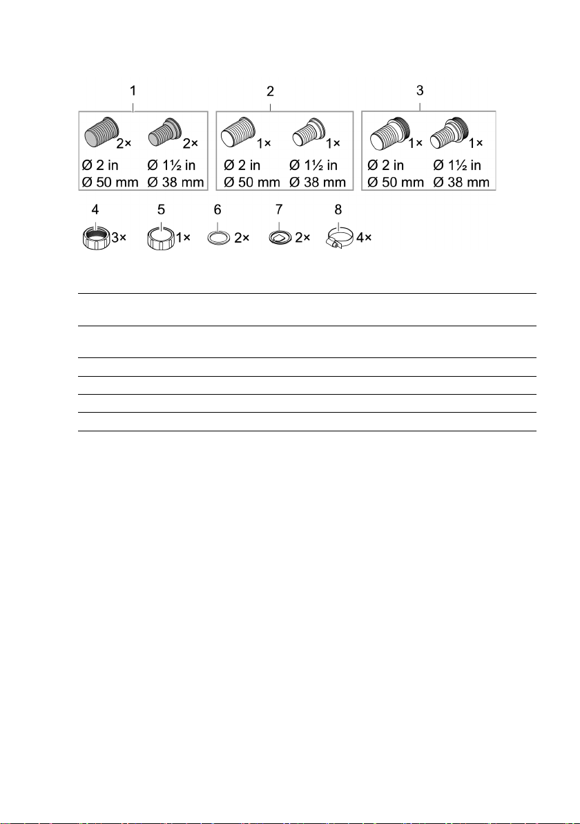
Connection components for installation.............................................................................................. 8
Function description................................................................................................................................ 9
Recommended filter pump ..................................................................................................................... 9
Symbols on the unit................................................................................................................................10
Installation and connection........................................................................................................................10
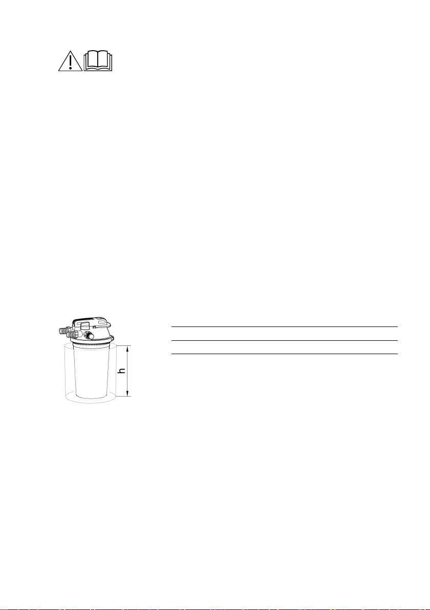
Installing the unit ....................................................................................................................................10
Establishing the connections ................................................................................................................ 12
Commissioning/start-up............................................................................................................................ 14
Switching the UVC clarifier on/off........................................................................................................ 15
Operation ...................................................................................................................................................... 15
Maintenance and cleaning.......................................................................................................................... 15
Cleaning the foam filters........................................................................................................................ 16
Removing/positioning the filter cover ................................................................................................ 17
Cleaning the unit and washing or replacing the foam filters............................................................ 19
Removing/installing the UVC unit head ............................................................................................. 22
Replacing the UVC lamp ........................................................................................................................ 23
Cleaning/replacing the quartz glass.....................................................................................................24
Replacing the cleaning rotor................................................................................................................. 26
Wear parts.....................................................................................................................................................27
Decommissioning/winter storage ............................................................................................................27
Troubleshooting.......................................................................................................................................... 28
Technical data.............................................................................................................................................. 29
Unit data .................................................................................................................................................. 29
Permissible water values....................................................................................................................... 30
Disposal ........................................................................................................................................................ 30

4
Questions, problems, missing parts?
Before returning the unit to your dealer, call us at 330-274-8317, Monday-Friday, or email us at
customerservice@atlantic-oase.com.
Safety information
Electrical connection
•Special regulations apply to electrical installation in outdoor areas. Only allow a qualified elec-
trician to perform the electrical installation.
– The qualified electrician has the required professional training, knowledge and skills to per-
form electrical installations in outdoor areas. The qualified electrician can detect potential
risks and adheres to regional and national standards, regulations and directives.
– For your own safety, please consult a qualified electrician.
•Only connect the unit if the electrical data of the unit and the power supply match.
•Only connect the device to a correctly installed socket.
•The device is to be supplied through a residual current device (RCD) having a rated residual op-
erating current not exceeding 30 mA.
•Extension cables and power distributors (e.g. outlet strips) must be suitable for outdoor use
(splash-proof).
•Protect open plugs and sockets from moisture.
Safe operation
•Do not use the unit, if electrical lines or the housing are damaged.
•Dispose of the unit if its power connection cable is damaged. The power connection cable can-
not be replaced.
•Do not carry or pull the unit by its power cable.
•Never make technical modifications to the unit.
•Only carry out work on the unit that is described in this manual.
•Only use original spare parts and accessories.
•Route lines so that they are protected from damage and nobody can trip over them.
•Should problems occur, please contact the authorized customer service or OASE.
WARNING
Serious injury or death due to dangerous electrical voltage is possible with an electrical device in
water operated with a voltage U > 12 V AC or U > 30 V DC.
Disconnect all electrical devices in the water from the power supply before reaching into the
water.
Disconnect the device from the power supply before starting work on the unit.

EN
5
WARNING
In the event of improper connection of the unit grounding, there is a risk of electric shock.
The unit must be grounded in order for the electrical current to be dissipated via the grounding
and to reduce the risk of electric shock in the event of a malfunction or failure.
Instructions for grounding:
The unit is equipped with a mains cable with grounding conductor and a plug with grounding
pin. The plug must be plugged into a suitable socket, which is installed and grounded accord-
ing to local regulations and ordinances and is protected by a FI protection switch (GFCI).
Do not modify the plug. Have a suitable socket installed by an electrician if the plug does not
fit into the socket.
Contact an electrician if you have any doubts as to whether the appliance is properly
grounded.
Intended use
Only use the product described in this manual as follows:
•For mechanical and biological cleaning of garden ponds
•In compliance with the technical specifications. (→ Technical data)
The following restrictions apply to the unit:
•This product is not suitable for general lighting, but is only intended for the purpose described
here.
•Never operate the UVC lamp outside the casing or use it for any other purpose. The UVC radia-
tion is harmful to the eyes and skin even in small doses.
•Never use the unit with fluids other than water.
•Do not use in conjunction with chemicals, foodstuff, easily flammable or explosive substances.
•Never run the unit without water.
•Do not use for commercial or industrial purposes.

6
Product description
Overview
FCL0007

EN
7
1
Water inlet for the pond water being cleaned
•
Connection G2
2
Opening ring with locking screw for locking the UVC unit head
•
To remove the UVC unit head, undo the opening ring.
3
Water outlet for the clean pond water
•
Connection G2
4
UVC unit head with temperature monitor
•
The UVC clarifier shuts down when overheated and is automatically reactivated after cooling
down
5
Turning valve for switching between water outlet and dirt water outlet
Water filtration and UVC radiation
Cleaning foam filters
6
Dirt water outlet for dirt water when cleaning the
foam filters
•
Connection G2
7
Indicator light for checking the function of the UVC clarifier
8
Cleaning handle
•Pulling compresses the foam filters and removes dirt particles
9
Filter lid
10
Clamping ring for fastening the filter lid on the container
11
Marking for the max. embedding depth
12
Container
13
Cleaning rotor, cleans the quartz glass during operation
•Only for FiltoClear 5200, 8200
14
Blue foam filter (10 ppi)
15
Red foam filter
(30 ppi)
16
Purple foam filter (20
ppi)
17
Closing disk for filter sponges, is connected to both cleaning rods
18
Cleaning rod, connecting cleaning handle and closing disk
19
Meshed tube, maintaining the foam filter spacing to the UVC water casing
20
UVC water casing, conveying water to the UVC lamp
21
Spacer, connecting two spacer disks with each other
•
The spacer prevent the foam filters from being compressed by the weight of the foam filters
above them
22
Quartz glass with
internal UVC lamp
23
Spacer disk, each positioned between two foam filters

8
Connection components for installation
FCL0012
1
Hose connector, transparent
•
Use: Water outlet, dirt water outlet
2
Hose connector, black
•
Use: Water inlet
3
Hose
connector, black with G2 outer thread
•Use: Open end of the dirt water hose, the cover cap is screwed onto the outer thread
4
Union nuts G2, for installing the hose connectors
5
Cover cap G2, for closing the dirt water outlet
6
Flat seal for black hose c
onnector and cover cap
7
Flow lug for transparent hose connector
8
Hose clip

EN
9
Function description
The filter pump presses the water into a pressure-tight container, where it passes several clean-
ing stages before returned into the pond.
Cleaning stage "filtering"
The water flows through the foam filters. Mechanical soiling is retained by the foam filters. Sus-
pended matter and bio sludge settle on the container bottom. Useful bacteria colonize the foam
filters, cleaning the water biologically. Their effect starts at a water temperature +50 °F ( +10 ) °C.
Foam filter
Properties
Blue (10
ppi)
High flow rate
Bacterial colonization for nitrification so that ammonium is first converted
to nitrite and then to nitrate
Purple (20
ppi)
Red
(30 ppi)
Low flow rate
Bacterial colonization for nitrification and denitrification to convert nitrate
to nitrogen
Cleaning level “UVC radiation”
The UVC clarifier irradiates the water with UV-C light. Green algae die, pathogenic agents are
killed.
Bypass
The bypass ensures that only approx. 70 % of the water is irradiated with UV-C light. This means
a sufficient radiation dosage is achieved even with high flow rates.
Biological cleaning effect
The maximum biological cleaning effect is achieved when the foam filters are fully colonized by
filter bacteria. This may take several weeks for new foam filters. Adding starter bacteria can sig-
nificantly accelerate the colonization process.
Cleaning foam filters
You can use waste water generated by cleaning foam filters to fertilize your garden.
Recommended filter pump
FiltoClear
3400
5200
8200
AquaMax Eco Premium
2000
3000
4000

10
Symbols on the unit
Read the operating instructions.
Installation and connection
Installing the unit
To be taken into consideration for planning:
•For operation at a swimming pond: Install the unit at a distance of at least min. 6.6 ft (2 m)
from the water.
•For operation at a pond: You can install the unit directly at the edge of the pond.
•Protect the pressure filter from direct sunlight.
•Route the return to the pond so that the water is returned to the pond e.g. through a water
course. This enriches the water with additional oxygen.
•Ensure that the inlet into the pond is max. 6.6 ft (2 m) above the filter lid.
Bury the pressure filter
A buried container is barely visible. The FiltoCap stone gray (art. no. 91645) cover for the filter lid,
available as an accessory, blends seamlessly into the pond landscape.
•Dig a hole close to the pond and place the container in the hole down to the maximum em-
bedding depth.
•Ensure that the ground is firm and horizontal.
FiltoClear
Embedding depth h
3400
0.8 ft (0.24 m)
5200
1.2 ft (0.36 m)
8200
1.6 ft (0.48 m)

EN
11
Installing the pressure filter on level ground
If you choose not to bury the pressure filter, position it so that it is hidden from sight e.g. cov-
ered by bushes.
•Install the unit near the pond.
•The ground must be firm and horizontal.
FCL0011

12
Establishing the connections
Hoses with a diameter of 1½ in (38 mm) or 2 in (50 mm) can be connected to the pressure filter.
The corresponding hose connectors are part of our scope of delivery.
Use hoses with a diameter of 2 in (50 mm) to keep the pressure loss in the hoses as low as
possible.
If you use a filter starter for start-up, fill the product into the container prior to carrying out
the following installation steps.
−It is easier to remove the filter cover if you first remove all hoses from the filter cover.
Connecting the inlet
Only use pressure hoses approved for at least the maximum pump pressure to connect the out-
let of the filter pump and the inlet of the pressure filter.
•Always use a hose clip to fasten the hose on a hose connector.
Connecting the outlet
Use a transparent hose connector with a flow lug. The transparent hose connector will allow you
to assess the water quality after filtration. The flow lug will show you the water flow.
•Push the hose onto the hose connector until only two segments on the hose connector re-
main uncovered.
– This will give you a sufficiently large view into the hose connector.
•Always use a hose clip to fasten the hose on a hose connector.
FCL0014

EN
13
Connecting the dirt outlet
The soiled water resulting from cleaning can be used for fertilisation. Connect a hose and route it
up to a suitable location (e.g. flower bed).
Use a transparent hose connector with a flow lug. The transparent hose connector will allow you
to assess the degree of soiling of the water when cleaning the foam filters. The flow lug will show
you the water flow.
•Push the hose onto the hose connector until only two segments on the hose connector re-
main uncovered.
– This will give you a sufficiently large view into the hose connector.
•Always use a hose clip to fasten the hose on a hose connector.
•Install the black hose connector with the G2 outer thread on the outlet of the hose. Close the
hose connector with the cover cap and the flat seal.
NOTE
Close the dirt outlet or the outlet of the connected hose with the cover cap and the flat seal.
This prevents unintended emptying of the pond. Only remove the cover cap to drain dirty water.
FCL0028

14
Commissioning/start-up
NOTE
The unit will be destroyed if it is operated with a dimmer. It contains sensitive electrical compo-
nents.
Do not connect the unit to a dimmable power supply.
The purely biological starter bacteria Oase AquaActiv BioKick activate the filter biology and
ensure maximum performance of your pond filter within only a few weeks. They immedi-
ately start removing nitrite, ammonium and ammonia from the water. We recommend fill-
ing the container with Oase AquaActiv BioKick
−during initial start-up,
−after manual cleaning or replacing the foam filters,
−after long shut-down periods or during start-up after a long winter break.
Start-up sequence:
1. If required, fill the container with Oase AquaActiv BioKick. (→ Removing/positioning the filter
cover)
2. Ensure that the hoses, cover cap for the dirt water outlet and the clamping ring with the
safety latch are firmly connected.
3. Turn the turning valve to “Filter water”.
4. Switch on the pond pump.
5. Only switch on the UVC clarifier when water emerges from the water outlet. (→ Switching the
UVC clarifier on/off)
– Never run the UVC clarifier without water flowing through.
– If you are using Oase AquaActiv BioKick, leave the UVC clarifier turned off for 24 hours. This
allows the starter bacteria to achieve optimum effectiveness.

EN
15
Switching the UVC clarifier on/off
•Switching on:Plug the power plug into the outlet.
– The unit switches on immediately.
– The indicator lamp lights up.
– The flow lug on the outlet will show you that water is flowing.
•Switching off: Pull the power plug from the outlet.
FCL0015
Operation
The pressure filter can remain in operation for the entire pond season (the filter pump and the
UVC clarifier are switched on).
•At water temperatures below 50 °F (10 °C), the filter biology is no longer active.
•Take the unit out of operation at water temperatures below 47 °F (8 °C) or, at the latest, when
freezing temperature are to be expected. (→ Decommissioning/winter storage)
•The UVC lamp is a wear part. Replace the UVC lamp after a specific operating duration to en-
sure optimal filtration power. (→ Replacing the UVC lamp)
Maintenance and cleaning
NOTE
Do not use aggressive cleaning agents or chemical solutions. These agents can damage the
housing, impair the function of the device and harm animals, plants and the environment.
Only clean the unit from the outside with clear water and a soft brush.

16
Cleaning the foam filters
The Easy Clean function is used to clean the foam filters. During cleaning, the filter pump is
switched on so that the dirt water is transported out of the pressure filter.
•Turn the turning valve to guide the water in the container to the dirt water outlet. This pre-
vents the dirt water from flowing back into the pond.
– Beforehand, remove the cover cap from the outlet hose for the dirt water.
•Pull the cleaning handle to compress the foam filters. The dirt particles are removed and flow
with the water via the dirt water outlet, for instance to a flower bed.
•The transparent hose connectors allow you to check the water flow and assess the degree of
soiling in the water during cleaning on the dirt water outlet. As soon as the water runs clear,
turn the turning valve back to “Filtering”.
•After cleaning, close the dirt water hose or the dirt water outlet with the cover cap and the
flat seal.
FCL0020

EN
17
Removing/positioning the filter cover
Removing the filter cover
How to proceed:
•Switch off the filter pump and pull the power plug of the UVC clarifier from the outlet.
•Remove all hoses from the filter cover (unscrew hose connectors).
•Undo the locking latch.
– Use flat nose pliers if the locking latch is hard to move.
•Open the clamping ring and remove the filter cover.
FCL0018

18
Positioning the filter cover
•Ensure that the O-ring on the container is positioned correctly on the container rim.
– Moisten the seal with water or grease the seal, if necessary, so that the filter head is easier
to push onto the container.
•Evenly and forcefully push the filter cover as far as possible onto the container.
– The filter ring must make full contact with the container, otherwise the clamping ring will
not close.
•Fasten the filter cover with the clamping ring and close the locking latch.
– The locking latch prevents the clamping ring from coming loose accidentally, which would
cause pond water to leak in an uncontrolled manner.
– Use flat nose pliers if the locking latch is hard to move.
•Attach all hoses (screw hose connectors in place).
FCL0019

EN
19
Cleaning the unit and washing or replacing the foam filters
Wear of the foam filters is caused by mechanical stress and normal ageing.
Insert new foam filters at the start of the season.
Disassembling the foam filter package
Prerequisite:
•The filter cover has been removed. (→ Removing the filter cover)
Place the filter cover upside down on a soft clean surface so that the foam filter package is on
top.
•Undo the two screws, remove the closing disc and remove the first foam filter.
•For every additional foam filter, undo the two spacers and remove the spacer disc and the
foam filter.
FCL0023

20
Cleaning
•Clean the container, the clamping ring, the filter cover, the UVC water housing and the
meshed tube with a powerful water jet.
– Pull off the meshed tube by pulling and simultaneously turning it clockwise.
•Wash each of the foam filters by forcefully compressing it under running water.
– If necessary, replace the foam filters.
FCL0030
This manual suits for next models
2
Table of contents
Languages:
Other Oase Water Dispenser manuals
Popular Water Dispenser manuals by other brands

Elkay
Elkay OFA25*1D Installation, care & use manual

Lancaster Water Treatment
Lancaster Water Treatment 7-LECS-50 Installation, operating and service manual

KENT
KENT 11063 Instruction handbook

Elkay
Elkay DSBWCT1 Installation, care & use manual

Grunbeck
Grunbeck softliQ:MD32 Operation manual

Powel Antica
Powel Antica AntiCa++ installation manual

Scalemaster
Scalemaster SL TWIN E Installation & operation manual

blupura
blupura BLUSODA HOT Series Use & maintenance manual

WaterLogic
WaterLogic WL350 Troubleshooting

Kärcher
Kärcher WPD 100 manual

First Sales
First Sales FEST Series Installation instructions and owner's manual

Envirotec
Envirotec ET42H owner's manual