Operating Instructions
for the Winterhalter MonoMatik 3 Softener
1 Safety notes
For safe operation of the MonoMatik 3 softener,
please read the safety notes listed here careful-
ly.
1.1 Explanation of symbols used
The following symbols are used in this manual:
Warns of potential defects or destruction of the
product when the provided safety measures are
not heeded.
An important tip is given here.
A useful tip is given here.
These arrows indicate procedural instructions
This symbol designates the results of your actions.
This symbol denotes lists
1.2 Intended use
The MonoMatik 3 softener is a device for water softening of fresh
water for use in commercial warewashers and may only be used
for this purpose. The MonoMatik 3 softener is installed between
the fresh water supply pipe and the warehwasher. The fresh water
must be of drinking water quality from a microbiological point of
view.
The MonoMatik 3 softener is a technical work equipment for com-
mercial use and is not intended for private use.
Any alterations to the design or to use of the device performed
without the written approval of Winterhalter Gastronom GmbH will
lead to the guarantee and product liability becoming void.
Winterhalter Gastronom GmbH will not accept liability for any
damage caused by failure to use the MonoMatik3 softener in ac-
cordance with its intended use.
1.3 Safety notes for maintenance and repairs
Maintenance and repairs may only be performed by authorised
Winterhalter service technicians. Unprofessional maintenance or
repairs may lead to considerable dangers for the user for which
Winterhalter cannot be held liable.
Only original spare parts by Winterhalter may be used for mainte-
nance or repairs. Use of spare parts that are not original spare
parts invalidates the warranty.
1.4 General safety notes
Read the safety and operational notes included in these operating
instructions carefully. Keep these operating instructions in a safe
place for later reference. Failure to observe the safety notes and
operating instructions voids all liability and warranty claims against
Winterhalter Gastronom GmbH.
Only work with the MonoMatik 3 softener after reading and under-
standing the operating instructions. Winterhalter Customer Ser-
vices will be glad to provide you with information on how to oper-
ate the device and how it functions. The MonoMatik 3 softener
may only be operated as described in these operating instructions.
2 Product description
The MonoMatik 3 consists of a mobile plastic container with a re-
movable cover. The regeneration salt is placed in the container.
Within this container is a cartridge that is filled with spare resin.
Water softening is based on the principle of ion exchange. The spare
resin in the cartridge binds with the hardening ions from the raw
water flowing through the device and releases other non-hardening
ions into the water. The softened water has a total hardness of 0 °dH.
The capacity of the spare resin is limited. This depends on the total
hardness of the raw water. This resin cartridge must be regenerated
when it has been exhausted. The control button on the cartridge
controls regeneration depending on the water hardness set. If water
is required during regeneration, raw water is provided via a bypass.
3 Installation and connection
3.1 Installation site requirements
The room must be frost-free.
A waste water drain must be located near the softener. The waste
water drain must not be situated higher than the side overflow on
the MonoMatik 3.
Ideally the room has a floor drain.
The installation location must be horizontal and even. Slight incli-
nations such as are usual in kitchens do not impair functioning,
however the softener should be secured against rolling.
The MonoMatik 3 should preferably be erected on the floor. If the
MonoMatik 3 is placed on a base, the castors should be removed.
It must be possible to remove the cover for topping up regenera-
tion salt.
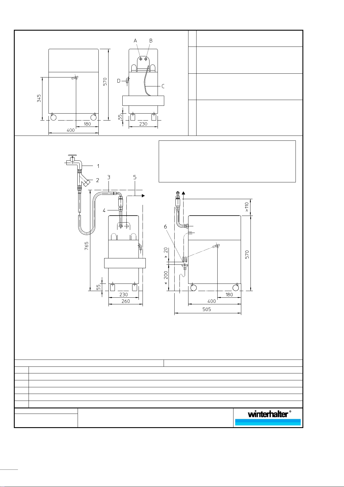
For water supply and drainage connections, see the connection
diagram on page 10.
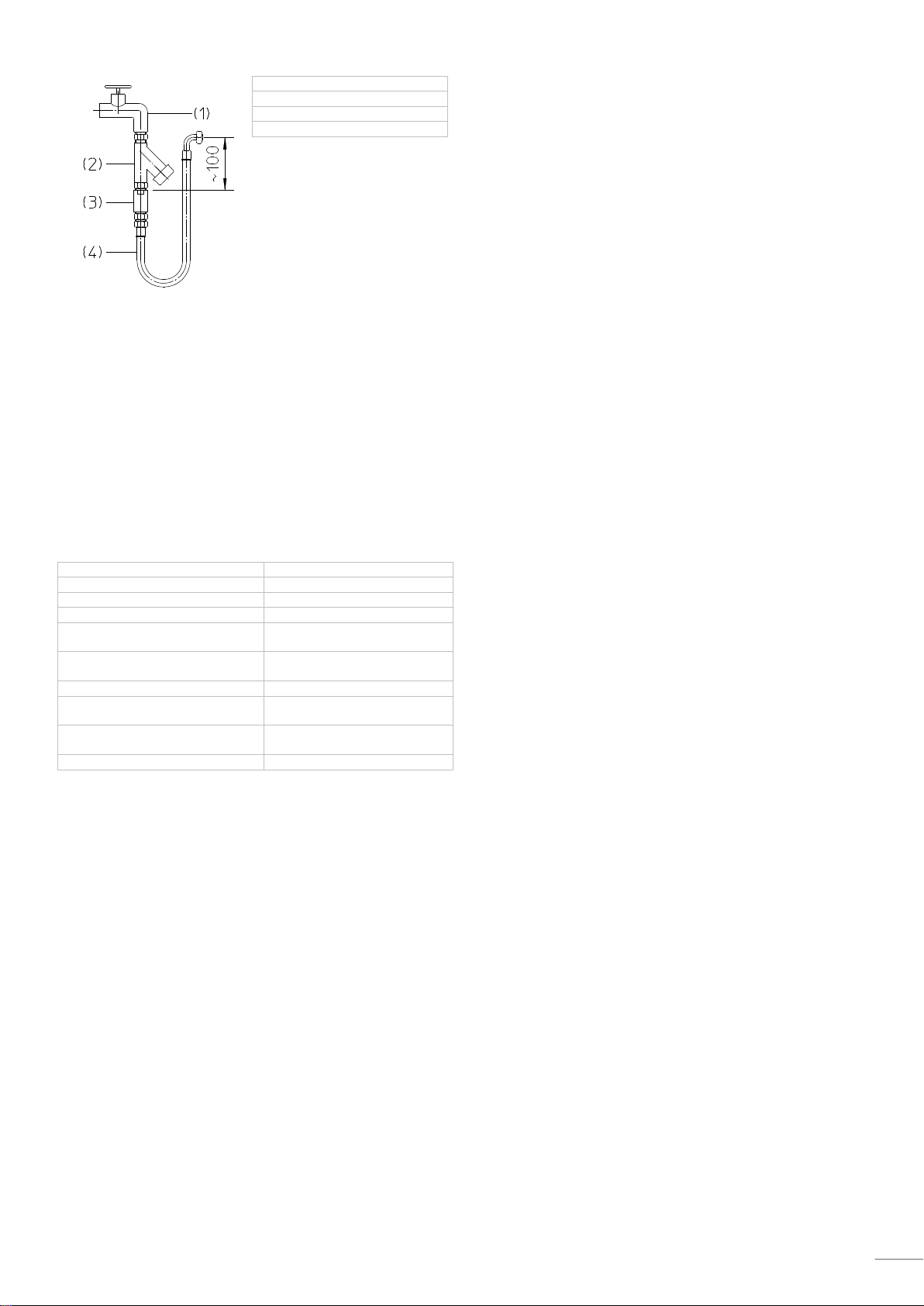
3.2 Connecting
Connection of the MonoMatik 3 to the drinking water
network and to waste water must be performed accord-
ing to the country-specific, local conditions by an ap-
proved water fitter.
National installation and operating regulations as well as
details on the connection diagram on page 10 must be
observed.
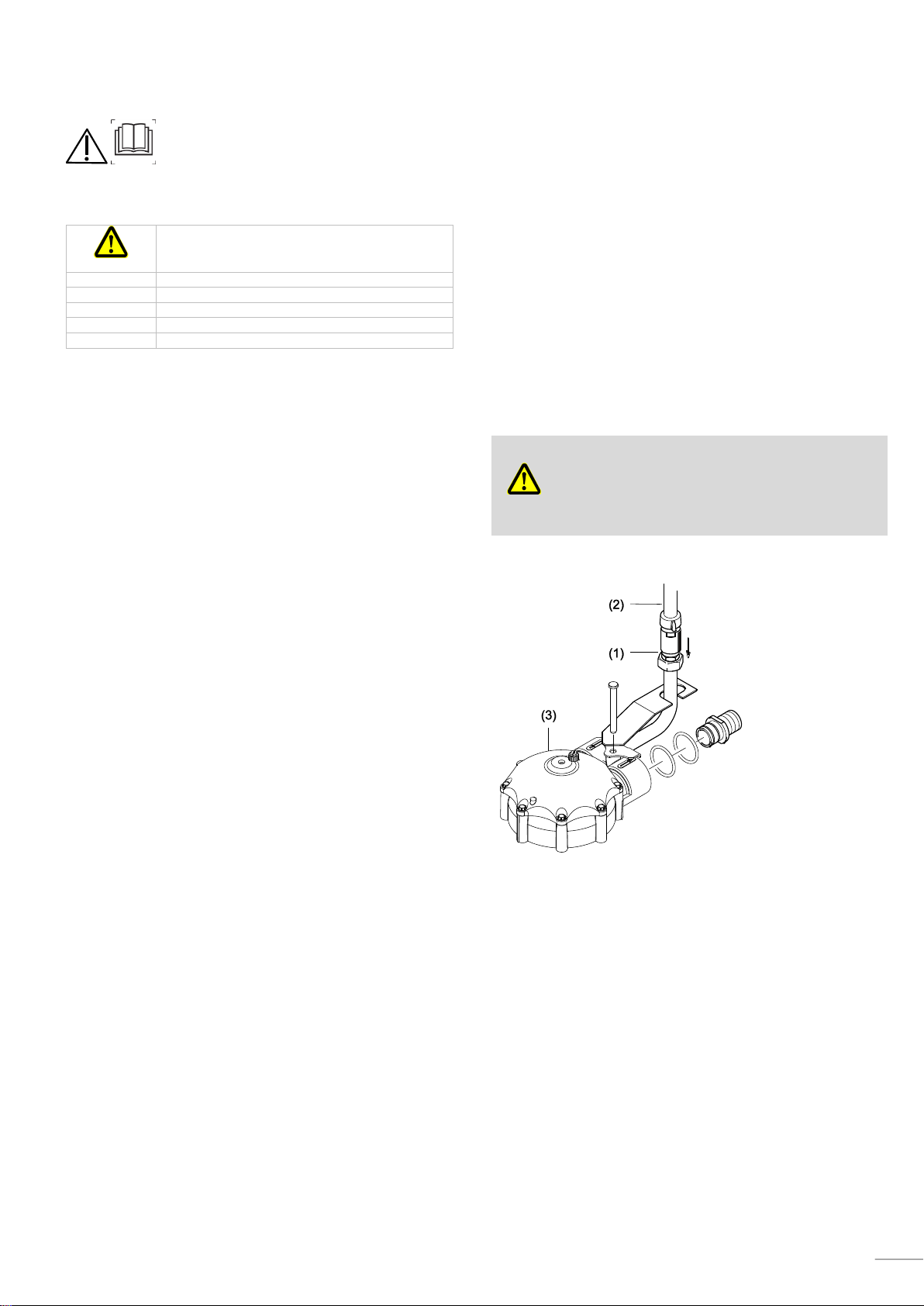
3.3 Connecting the water safety device
A water safety device (1) must be used in order for the MonoMatik 3
to be operated in accordance with DIN requirements. A kit is availa-
ble from Winterhalter for this purpose.
The kit contains a backflow preventer type HD in accordance with
DIN EN 1717.
Installation of the water safety device is shown in the drawing.
Should national guidelines not require a check valve or anti-vacuum
device, the water supply hose (2) is connected directly at the control
head (3).