Dawson Tools DDM350 User manual

Pen-Type Digital Multimeter
User’s Manual
DDM350

CONTENTS CONTENTS
Out of the Box.............................................1
Accessories................................... ...2.........
Safety Information......................................2
INTRODUCTION .............................. ........4.
Overview ................................... ...4.............
Buttons and Components ............ ...4.............
Display Description........... ...6.......................
USING THE METER........................ ........7....
Preparation .......... ...7..................................
DC/AC Voltage Measurement........ ...7...........
DC/AC Current Measurement......... ...8..........
Resistance Measurement.......... ...9...............
Diode Test .......... ...9....................................
LIMITED WARRANTY AND
LIMITATION OF LIABILITY. .......... ...........1. ......
Safety Symbols ................................ ......3....
Certification................................ ......4.........
Capacitance Measurement. .10......................
Continuity.......... .10.....................................
Frequency/Duty Cycle.......... .11....................
Data Hold . ......... ..12. ...................................
SPECIFICATIONS........................ ...... 13... ...
General Specification ......... .13.....................
Technical Specification..............................14
MAINTENANCE AND REPAIR......... .......18...
Repair.......... ..18..........................................
Test Leads Replacement ........ ..18.................
Replacing the batteries ........ .18....................
CONTACT DAWSON........................ ......19...
Backlight .......... .12......................................
Work light.......... .12......................................
NCV (Non-Contact Voltage). ..12....................
Auto Off. ......... ...12. .....................................

01 02
LIMITED WARRANTY AND
LIMITATION OF LIABILITY
This instrument from Dawson Tools Inc. will be free
from defects in workmanship and material for three
years from the date of original purchase.This warranty
does not cover defects resulting from damage caused
by the user such as drops, neglect, misuse,
unauthorized alteration, usage outside of specified
conditions, contamination, or improper repair/
maintenance.To receive service on the instrument if it
becomes necessary during the warranty period,
contact your nearest Dawson authorized service center
at (800) 898-6991 or visit www.DawsonTools.com to
obtain a return authorization (within the US only).
A return authorization is necessary before returning
any instrument to Dawson; no service will be provided
without a return authorization.The user is responsible
for properly packing the unit and charges such as
shipping, freight and insurance charges.The extent of
Dawson's liability is limited solely to the repair/
replacement of the instrument.The above warranty in
its entirety is inclusive and no other warranties, written
or oral, are expressed or implied.
Out of the Box
Check the meter and accessories thoroughly before
using the meter. Contact your local distributor if the
meter or any components are damaged or malfunction.
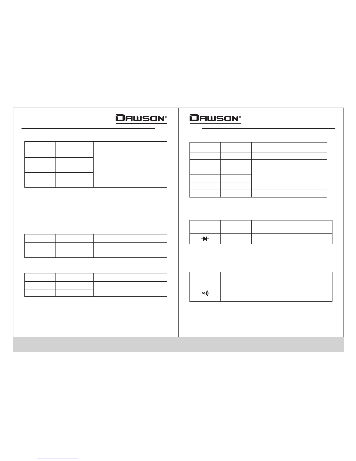
Accessories
Test Lead
1.5V AAA Battery
Case
1
2
3
4
1 pcs
1 pcs
2 pcs
1 pcs
Safety Information
To reduce the risk of fire, electrical shock, product
damage or personal injury, please follow the safety
instructions described in the user’s manual. read
the manual before using the meter.
Warning
To ensure safe operation and life of the meter, do
not place the meter in any environment with high
pressure, high temperature, dust, explosive gas
or vapor.
Warning
1.Avoid shaking, dropping or any kind of impacts when
using or transporting the meter.
2.To avoid electric shock or personal injury, repairs or
servicing not covered in this manual should be
performed only by qualified personnel.
3.Avoid direct exposure to sunlight to ensure extended
life of the meter.
4.Do not place meter in a strong magnetic field; this may
cause false readings.
5.Use only the batteries indicated in the Technical Spec.
User’s Manual
51 pcs
Alligator Clip & cable

Important safety information, please
refer to the user’s manual
Earth ground
Indicates compliance with requirements
for double insulation
03 04
6.Avoid exposing batteries to humidity. Replace batteries
as soon as the low battery indicator appears.
7.Please keep the original packing for future shipping
purposes (ex. Calibration)
8.After opening the box, check for any damage during
delivery.
Safety Symbols
Important Safety Information
• Repair or maintenance should be implemented by
trained personnel only.
Certification
CAT I :This meter has met IEC1010-1 standard with an
overvoltage category (CAT III) and pollution degree of 2.
The meter comp ies to EMC requirements.
II
l
Fuse must be replaced with ratings
specified in the manual.
Conforms to IEC1010-1 standards for
overvoltage in category III installations
with a pollution degree of II.
Complies with European Union (EU)
standards
CE
CATIII
Complies with U.S. and Canadian safety
standards.
• Never use the meter to measure voltages that might
exceed 600V DC/AC above earth ground in category
III installations.
• Always be careful when working with voltage above
60V DC or 30VAC RMS. Keep fingers behind the probe
barriers while measuring.
• Inspect test leads and probes for cracks, breaks or
crazes on the insulation before using the meter.
Introduction
Overview
The DDM350 is a portable pen-type digital multimeter
featuring DC/AC voltage and current measurements,
resistance, capacitance, continuity, diode testing,
frequency and duty cycle, auto/manual range, worklight,
and an LCD w/backlight for easy reading. The slim and
lightweight design is mobile and ideal for both
professionals and hobbyists.
Figures and Components
Buttons and Components
1.Test Probe (+)
2.Probe Cap
3.NCV Indicator
4.Protective Ring
5.LCD Display
6.Rotary Switch
7.FUNC (Function) Button
8.RAN (Range) Button
9. (Work light) Button
10.NCV (Non-Contact Voltage) Button
11.H/ (Hold/Backlight) Button
12.Hz/% (Frequency/Duty Cycle) Button
13.COM Jack (-)
03

05 06
Buttons and Components Description
+ Input for V/A/Ω/ / / /Hz/%
COM Common terminal
Probe Cap Protective cap to be used when making
CAT III or above measurements
Protective Ring Keep hand behind the ring for safety
FUNC Button
Switch between AC/DC or between
resistance, continuity, diode or
capacitance
RAN Button Choose auto or manual range
Button Hold to turn on the work light
Hold data reading/turn on/off backlight
NCV Button Hold to activate Non-Contact Voltage
measurement
H/ Button
Switch between frequency/duty cycle
functions
Hz/% Button
Select different functions
Rotary Switch
Probe
Display Description
°C°F
n,µ,m,k,M nano, micro, milli, kilo, mega
ΩOhms (resistance)
FFarad (capacitance)
A
V
Ampere (current)
Volt (voltage)
Diode
Buzzer
Data hold
AUTO Auto range
Low battery indicator
AC Alternating Current
DC Direct Current
%Duty Cycle
Frequency
Hz
Celsius/Fahrenheit
12345678910 11 12 13

07 08
Using the Meter
Preparation
• Select a function and a range for the item to be
measured using the rotary switch and “RAN” button if
necessary. In manual range if the range to be measured
is unknown, start with the highest range.
• In manual range, “OL” is displayed when overload
occurs. Choose a higher range.
• To perform measurement, first connect the test lead to
common (COM) input then connect the probe tip of the
Meter to the circuit to be tested.
• If the battery voltage is less than 2.4V,“ ”is displayed.
Please change the batteries.
DC/AC Voltage Measurement
Use caution when measureing high voltage circuits
to avoid electrical shock and injury. do not test
voltages higher than dc/ac 600v.
Warning
•
or higher measurements.
• Insert the black test lead or lead with test clip in the
“COM” jack.
• Set the rotary switch to the “V ”position.
• Press the “FUNC” button to switch between DC and AC
measurements. Manual range can be selected by
pressing the “RAN” button. Hold “RAN” to go back to
Auto range.
• Connect the probe tip of the meter and tip of the test lead
(or test clip) across the voltage source or load.
• Read the measurement on the display. The polarity of
the meter ’s “+” probe will be indicated.
Make sure the probe cap is screwed on if making CAT III
NOTE:
At small voltage ranges the meter may show unsteady
readings when test leads are not connected to the circuit,
this is normal because of the sensitivity of the meter.
When the meter is connected to the circuit, true readings
will be displayed.
DC/AC Current Measurement
Use caution when measureing high voltage circuits
to avoid electrical shock and injury. do not test
voltages higher than dc/ac 600v.
Warning
• Make sure the probe cap is screwed on if making CAT III
or higher measurements.
• Insert the black test lead or lead with test clip in the
“COM” jack.
• Set the rotary switch to the “mA ”position.
• Press the “FUNC” button to switch between DC and AC
measurements. Manual range can be selected by
pressing the “RAN” button. Hold “RAN” to go back to
Auto range.
• Connect the probe tip of the meter and tip of the test
lead (or test clip) across the power source or load.
• Read the measurement on the display. The polarity of
the meter ’s “+” probe will be indicated.

09 10
Resistance Measurement
To avoid electrical shock and injury, power off the
circuit and discharge the capacitance before
measuring resistance.
Warning
• Insert the black test lead or lead with test clip in the
“COM” jack.
• Set the rotary switch to the “ ” position. Manual range
can be chosen by pressing the “RAN” button. Hold
“RAN” to go back to Auto range.
• Connect the probe tip of the meter and tip of the test
lead (or test clip) across the resistance or circuit under
measurement and read the measured value on the
display.
Ω
NOTE:
•
reading if the measured resistance is above 1MΩ.
• When the input is not connected (i.e. an open circuit)
“OL” will be displayed.
The meter may take a few seconds to reach steady
Diode Test
•
• Set the rotary switch to the “ ”position. Press “FUNC”
to choose diode measurement; “ ”is displayed.
• Connect the probe tip of the meter and tip of the test
lead (or test clip) across the diode under measurement
and read the measured value on the display.
Insert the black test lead or test clip in the “COM” jack.
NOTE:
The Meter shows the forward voltage drop. If the lead
connection is reversed, “OL” is displayed.
Capacitance Measurement
To avoid electrical shock and injury, power off the
circuit and discharge the capacitance before
measuring capacitacne.
Warning
• Insert the black test lead or lead with test clip in the
“COM” jack.
• Set the rotary switch to the “ ”
• position.Press “FUNC” twice to choose capacitance
measurement.There is no manual range available in
capacitance mode.
• Connect the probe tip of the meter and tip of the test lead
(or test clip) across the capacitance or circuit under
measurement and read the measured value on the
display.
NOTE:
The meter may take a few seconds to reach steadyeading
when making high capacitance measurements.
Continuity
To avoid electrical shock and injury power off the
circuit and discharge the capacitance before
measuring continuity.
Warning
•
“COM” jack.
• Set the rotary switch to the “ ”position. Press “FUNC”
3 times to choose continuity test; “ ”is displayed.
• Connect leads to the circuit terminals.
• If continuity exists (i.e. resistance is less than 50Ω), the
built-in buzzer will sound.
Insert the black test lead or lead with test clip in the

11 12
Data Hold
• If the result is an open circuit (or the measured circuit
resistance is higher than 200Ω) “0L” is displayed.
Frequency/Duty Cycle
Use caution when measureing high voltage circuits
to avoid electrical shock and injury. do not test
voltages higher than dc/ac 600v.
Warning
• Make sure the probe cap is screwed on if making CAT III
or higher measurements.
• Insert the black test lead or test clip in the “ jack.
• Set the rotary switch to the “Hz%” position; “Hz” is
displayed.
• Connect the probe tip of the meter and tip of the test
lead (or test clip) across the source or load for
measurement and read the measured frequency on the
display.
• Press “Hz%” to switch to duty cycle measurement; “%”
is displayed.
• Connect the probe tip of the meter and tip of the test
lead (or test clip) across the source or load for
measurement and read the measured duty cycle on
the display.
• Alternatively, while in AC voltage or AC current modes,
pressing the “Hz%” button will switch to frequency
mode.Press the button again to switch to duty cycle.
Press the button a third time to return to voltage/current
mode.
COM”
To hold a reading, press the“ / ”button and the current
reading will be held on the display. Press the button again
to return to normal reading.
Backlight
• Hold the“ / ”button for two seconds to turn on
backlight. The backlight will go off automatically after
10 seconds.
• Hold the“ / ”button again to manual turn off the
backlight.
Work light
While the meter is on in any position, hold the “ ”
button to turn on the work light.Use this in areas that are
poorly illuminated to make measurements easier.
NCV (Non-Contact Voltage)
While the meter is on in any position, hold the “NCV”
button to turn check for the presence of voltage. Move
the top of the meter toward the voltage source and if the
voltage detected is >110VAC, the meter will beep and
the NCV indicator will flash.
NOTE:
Do not rely solely on NCV detection to determine the
presence of voltage in a conductor.Socket design,
insulation, interference, etc. can affect detection.
Auto Off
When not in use, the Meter will automatically turn off after
approx. 15 minutes. After auto off, press “FUNC” to turn
the power back on. The Meter will beep 5 times 1 minute
before and a long beep right as it turns off.
Hold the “FUNC” button while turning on the meter to
disable auto off.

13 14
Specifications
General Specifications
Environment Conditions 600V CAT. III
Pollution Degree 2
Maximum Operating Altitude 7000 Ft (2000m)
Operating Temperature
0~40°C, 32°F~122°F
(<80% RH, <10℃
non-condensing)
Display 20mm LCD
Max. ValueDisplay 3999 (3 3/4 digit display)
Polarity Indication: “-”indicates negative
polarity.
Overrange Indication Display “OL .shows ”
Sampling Time approx. 0.4 second
Unit Display Displays function and
measured value.
Low Battery Indication “ ”displayed
Fuse Protection: FF400mA/600V
Storage Temperature
-10~50 °C, 14°F~122°F
(<70% RH, battery
removed)
Max. Voltage Between
Terminals And Earth Ground 600V DC or AC
Auto Ranges and Manual Range
Auto power off time 15 min.
Power Supply 1.5V×2 AAA battery.
Dimension 8.9x1.6x1.4 in.
(227×40×35mm)
Weight approx. 4.48oz (127g)
including battery sss
Technical Specifications
DC voltage
Resolution
0.1mV
Accuracy
400mV
0.001V
0.01V
0.1V
1V
4V
40V
400V
600V
±(0.5% reading + 3 digits)
Range
-
-
-
Input Impedance: 10MΩ
Overload Protection: 400mV range: 250V DC or AC rms
4V to 600V ranges: DC 600V or AC 600V rms
Max. Input Voltage: 600V DC

Function
Range
If resistance is lower than 50Ω, the built in
buzzer will sound.
-
-
Open circuit voltage: 1.0V
Overload Protection: 250V DC or RMS AC
Resolution Function
Range
Displays diode forward voltage
0.001V
-
-
-
Forward DC Current: 1mA
Reversed DC Voltage: 3.2V
Overload Protection: 250V DC or RMS AC
Resistance
Resolution
0.1Ω
Accuracy
400Ω
0.001kΩ
0.01kΩ
0.1kΩ
4kΩ
40kΩ
400kΩ
4MΩ
±(1.0% reading + 3 digits)
Range
±(1.0% reading + 5 digits)
- Open circuit voltage:1.0V
- Overload protection: 250V DC or AC (RMS)
40MΩ0.01MΩ
0.001MΩ
±(1.0% reading + 1 digits)
15 16
AC voltage
Resolution
0.1mV
Accuracy
±(0.8% reading + 3 digits)
400mV
0.001V
0.01V
0.1V
1V
4V
40V
400V
600V
±(0.8% reading + 3 digits)
Range
±(1.0% reading + 3 digits)
- Input Impedance: 10MΩ
Overload Protection: 400mV range: 250V DC or AC rms
4V to 600V ranges: DC 600V or AC 600V rms.
-
- Frequency range: 40 to 400hz
- Response: True RMS
- Maximum input voltage: 600V AC rms
Resolution
0.01mA
Accuracy
±(1.5% reading + 3 digits)
40mA
0 1 mA.400mA
Range
- Overload protection: resettable fuse 400mA/600V
DC Current
AC Current
Resolution
0.01mA
Accuracy
±(2.0% reading + 3 digits)
40mA
0 1 mA.400mA
Range
-
- Frequency Range: 40 to 400Hz
- Response: True RMS
Overload protection: resettable fuse 400mA/600V
Diode
Continuity

17 18
- Overload Protection: 250V DC or AC RMS
Function
±(0.5% reading + 3 digits)
Hz
%
Range
0-10MHz
1-99%
Frequency/Duty Cycle
Accuracy
±(3.0% reading + 3 digits)
Capacitance
Resolution
0.001nF
Accuracy
4nF
0.01nF
0.1nF
1nF
40nF
400nF
4µF ±(4.0% reading + 10 digits)
Range
0.01µF
40µF
0.1µF
400µF
1µF
4mF
0.01µF
40mF
- Overload Protection: 250V DC or AC RMS
Maintenance and Repair
Repair
Please follow these steps closely if the meter is not
functioning properly:
• Check the batteries; replace with new batteries if low
battery indicator “ ”appears.
• Follow the user’s manual to confirm all procedures.
• Before sending the meter back for repair, include a
description of the problems encountered. Remove
batteries and pack the meter well to avoid damage
during delivery; Dawson does not cover damage due to
delivery.
• Repair or service not covered in this manual should be
performed only by the authorized service center or
qualified personnel.
Test Leads Replacement
Replace the test leads with identical or compatible
leads. lead spec:600V 10A.
Warning
Replace new leads if the current leads are worn or
damaged.
Replacing the batteries
Follow these steps to replace the batteries:
• Turn off the meter.
• Loosen the battery cover and remove the cover from
the case’s bottom.
• Remove the batteries and replace them with new ones.
• Re-attach the battery cover to the case’s bottom and
tighten the screw.

19
Contact Dawson
Dawson Tools, Inc.
1142 S. Diamond Bar Blvd., #858
Diamond Bar, CA 91765
Phone:
www.DawsonTools,com
(310) 728-6220
Features
• True RMS
• LCD Display
• Auto and Manual Range
• Auto Power Off
• Diode Test
• Audible Continuity
• Non-Contact Voltage Detection
• Work light
• Backlight
• Data Hold
• Low Battery Indicator
00-05-3544
Table of contents
Other Dawson Tools Multimeter manuals

Dawson Tools
Dawson Tools DDM190 User manual

Dawson Tools
Dawson Tools DDM640 User manual

Dawson Tools
Dawson Tools DDM450 User manual

Dawson Tools
Dawson Tools DAN120 User manual

Dawson Tools
Dawson Tools DDM453 User manual

Dawson Tools
Dawson Tools DDM190D User manual

Dawson Tools
Dawson Tools DDM230C User manual