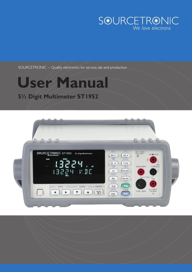
Sourcetronic ST1963 User manual

SOURCETRONIC −Quality electronics for service, lab and production
ST1963 6½ Digit Multimeter
User Manual

2
Contents
Chapter 1 General Information.................................................................................................................................. 4
1.1 Feature Overview......................................................................................................................................... 4
1.2 Operating Environment ............................................................................................................................... 4
1.3 Dimensions and Weight............................................................................................................................... 4
1.4 Safety symbols and Precautions .................................................................................................................. 5
1.5 Unpacking Inspection.................................................................................................................................. 5
1.6 Mark............................................................................................................................................................. 5
1.7 Warranty....................................................................................................................................................... 6
1.8 Limitation of Warranty ................................................................................................................................ 6
Chapter 2 Specifications and Features....................................................................................................................... 7
2.1 Specifications............................................................................................................................................... 7
2.2 Supplementary specifications.....................................................................................................................11
Chapter 3 Instructions for use.................................................................................................................................. 12
3.1 Front Panel Menu Reference ..................................................................................................................... 12
3.2 Measurement ............................................................................................................................................. 14
3.2.1 DC Voltage...................................................................................................................................... 14
3.2.2 DCV Ratio ...................................................................................................................................... 15
3.2.3 AC Voltage...................................................................................................................................... 15
3.2.4 DC Current...................................................................................................................................... 17
3.2.5 AC Current...................................................................................................................................... 18
3.2.6 Resistance 2W ................................................................................................................................ 19
3.2.7 Resistance 4W ................................................................................................................................ 21
3.2.8 Capacitance Measurement.............................................................................................................. 22
3.2.9 Diode .............................................................................................................................................. 23
3.2.10 Continuity..................................................................................................................................... 24
3.2.11 Temperature test............................................................................................................................ 25
3.2.12 Frequency measurement............................................................................................................... 26
Chapter 4 Arithmetical Operation............................................................................................................................ 28
4.1 Null Operation........................................................................................................................................... 28
4.2 Statistics..................................................................................................................................................... 28
4.3 Limit .......................................................................................................................................................... 28
4.4 dB Calculation........................................................................................................................................... 28
4.5 dBm Calculation........................................................................................................................................ 29
4.6 mX+b......................................................................................................................................................... 29
4.7 Percent....................................................................................................................................................... 29
Chapter 5 Interface .................................................................................................................................................. 30
5.1 RS-232 interface........................................................................................................................................ 30
5.1.1 RS-232 Interface Operation............................................................................................................ 31
5.2 Handler Interface....................................................................................................................................... 33
5.2.1 Handler setup.................................................................................................................................. 34
5.3 USB Interface ............................................................................................................................................ 35
5.3.1 USB Host........................................................................................................................................ 35

3
5.4 LAN Interface............................................................................................................................................ 35
5.5 GPIB Interface........................................................................................................................................... 36
5.5.1 GPIB Bus........................................................................................................................................ 36
5.5.2 Setting the GPIBAddress............................................................................................................... 37
5.5.3 General Bus Commands ................................................................................................................. 37
5.5.4 Setting through the interface........................................................................................................... 38
Chapter 6 System Settings....................................................................................................................................... 39
6.1 Set the language......................................................................................................................................... 39
6.2 Setting the date/time.................................................................................................................................. 39
6.3 Setting the buzzer and brightness.............................................................................................................. 39
6.4 Setting the format of the digital display..................................................................................................... 39
Chapter 7 SCPI Command Reference ..................................................................................................................... 40
7.1 SCPI Language Profile.............................................................................................................................. 40
7.1.1 Grammatical conventions............................................................................................................... 40
7.1.2 Command separator........................................................................................................................ 40
7.1.3 Using MIN, MAX and DEF parameters......................................................................................... 41
7.1.4 Query Parameter Settings ............................................................................................................... 41
7.1.5 Parameter Type ............................................................................................................................... 41
7.2 Subsystem commands................................................................................................................................ 42
7.2.1 CONFigure Subsystem ................................................................................................................... 42
7.2.2 MEASure subsystem....................................................................................................................... 45
7.2.3 TRIGger subsystem ........................................................................................................................ 48
7.2.4 [SENSe:]VOLTage subsystem........................................................................................................ 51
7.2.5 [SENSe:]CURRent Subsystem....................................................................................................... 54
7.2.6 [SENSe:]{RESistance|FRESistance} subsystem............................................................................ 56
7.2.7 [SENSe:]{FREQuency|PERiod} Subsystem.................................................................................. 57
7.2.8 [SENSe:]TEMPerture Subsystem................................................................................................... 59
7.2.9 [SENSe:]CAPacitance subsystem................................................................................................... 60
7.2.10 SYSTem Subsystem - I/O Configuration...................................................................................... 61
7.2.11 SYSTem Subsystem - General Command .................................................................................... 63
7.2.12 DATA2 subsystem ........................................................................................................................ 64
7.2.13 NULL subsystem.......................................................................................................................... 64
7.2.14 CALCulate:SCALe subsystem ..................................................................................................... 66
7.2.15 CALCulate: LIMit subsystem....................................................................................................... 68
7.2.16 CALCulate: AVERage Subsystem................................................................................................ 68

4
Chapter 1 General Information
Thank you for purchasing and using our products. Before using the instrument, first inspect it according to the
“1.5 Unpacking Inspection” section of this chapter in this manual. If there is any discrepancy, please contact our
company as soon as possible to protect your rights. If you still have questions after reading this manual, please
contact your local distributor or call our company's engineers directly for further consultation.
1.1 Feature Overview
The ST1963 is a 6½ digital multimeter with high accuracy, stability and speed. The digital multimeter provides a
maximum measurement speed of 1000 readings/sec. ST1963 has a 0.0035% DC voltage basic accuracy, 0.0100%
basic resistance accuracy and other high performance.
ST1963 has broad measurement ranges:
DC voltage from 0.1μV to 1000V
AC voltage from 0.1μV to 750V, peak value of 1000V
AC/DC voltage from 1μV to 750V (RMS)
DC current from 10nA to 10A
AC current from 10nA to 10A
Resistance measurement from 0.01mΩ to 120MΩ
Frequency from 2Hz to 1MHz
Some additional capabilities of Model ST1963:
Full range of functions: In addition to those listed above, ST1963 functions include period, dB, dBm,
continuity, diode testing, arithmetical operation (mX+b) and percent.
Programming languages and remote control interfaces: ST1963 provides the SCPI programming
language and the remote control interface ports USB Device, RS-232C, LAN, IEEE-488/GPIB (option),
and Handler (option) interface.
Readings and instrument settings: Up to 10,000 readings can be stored in local mode.
Completed calibration: The unit can be calibrated either from the front panel or through the remote
control interface.
1.2 Operating Environment
Power supply: 110V/220V ±10%
Line frequency: 50Hz / 60Hz ±5%
Power consumption: ≤30VA
Operating temperature: 0°C to 40°C
Humidity: ≤ 90%RH
1.3 Dimensions and Weight
Dimensions (W×H×D): 225mm×100mm×355mm
Net weight: Around 2.5Kg

5
1.4 Safety Symbols and Precautions
The symbol on the instrument indicates that user should refer to the operating instructions located in the
manual before performing.
The symbol on the instrument shows that high voltage may be present on the terminal(s). Be careful to
avoid personal contact with these voltages.
The symbol on the instruments means earth grounding.
The WARNING heading used in the manual explains high voltage danger that might result in personal injury or
death. Always read the associated information very carefully before performing the indicated procedure.
The CAUTION heading in the manual reminds user that hazards could damage the instruments if not according
to operating instructions. Such damage may invalidate the warranty.
1.5 Unpacking Inspection
Your ST1963 was carefully inspected mechanically and electrically before shipment. After unpacking all items
from the shipping carton, please check for any obvious signs of physical damage that may have occurred during
transportation. Report any damage to the shipping agent immediately. Save the original packing carton for
possible future reshipment. The following items are included with every Model ST1963 order:
Model ST1963 61/2Digital Multimeter
Test leads (Model ST26036)
USB interface connection cable (ST26017)
Power cord
T500mAL fuse
T3.15AL fuse
Test report
This operation manual
Other optional accessories, if ordered
Verify that you have received all the items above when you get the multimeter. If anything is missing, please
contact our representative or our sales office.
Note: The IEEE-488 interface and Handler interface of this instrument are optional and need to be purchased
separately. These two interfaces cannot be installed at the same time.
1.6 Mark
The following marks are on each instrument panel or nameplate:
•Manufacturer's name or trademark
•Product name and model
•Product number

6
•Manufacturing measuring instrument license signs and numbers
•Test terminal mark
1.7 Warranty
Sourcetronic warrants this product to be free from defects in material and workmanship for a period of one year
from the date of shipment. During the warranty period, we will, at our option, either repair or replace any product
that proves to be defective.
1.8 Limitation of Warranty
This warranty does not apply to defects resulting from product modification without our express written consent,
or misuse of any product or part. This warranty also does not apply to fuses, software, or problems arising from
normal wear or failure to follow instructions.
THIS WARRANTY IS IN LIEU OF ALL OTHER WARRANTIES, EXPRESSED OR IMPLIED, INCLUDING ANY
IMPLIED WARRANTY OF MERCHANTABILITY OR FITNESS FOR A PARTICULAR USE. THE REMEDIES
PROVIDED HEREIN ARE BUYER’S SOLE AND EXCLUSIVE REMEDIES.
NEITHER SOURCETRONIC NOR ANY OF ITS EMPLOYEES SHALL BE LIABLE FOR ANY DIRECT,
INDIRECT, SPECIAL, INCIDENTAL OR CONSEQUENTIAL DAMAGES ARISING OUT OF THE USE OF ITS
INSTRUMENTS AND SOFTWARE EVEN IF SOURCETRONIC HAS BEEN ADVISED IN ADVANCE OF THE
POSSIBILITY OF SUCH DAMAGES. SUCH EXCLUDED DAMAGES SHALL INCLUDE, BUT ARE NOT
LIMITED TO: COSTS OF REMOVAL AND INSTALLATION, LOSSES SUSTAINED AS THE RESULT OF
INJURY TO ANY PERSON, OR DAMAGE TO PROPERTY.

7
Chapter 2 Specifications and Features
Technical description of test performance data
One year calibration cycle
Operating environment temperature: 18 °C ~ 28 °C
Calibration environment temperature TCAL=23°C
Calibrated after warming up for 60 minutes
Accuracy data specification: ± (% of reading + % of full range)[1]
Operating humidity environment: at 0 °C ~ 18 °C, ≤80%RH (when the resistance range is ≥10M, ≤70% RH),
at 28°C~40°C, ≤70%RH
2.1 Specifications
All values given as ± (% of reading + % of full range)[1]
DC voltage specification
Range
Resolution[4]
24 hours [3]
TCAL ± 1°C
90 days
TCAL ± 5°C
1 year
TCAL ± 5°C
Temperature
coefficient/°C[2]
100.0000mV[5]
0.1uV
0.0030+ 0.0030
0.0040 + 0.0035
0.0050 + 0.0035
0.0005 + 0.0005
1.000000V
1uV
0.0020+ 0.0006
0.0030 + 0.0007
0.0040 + 0.0007
0.0005 + 0.0001
10.00000V
10uV
0.0015+ 0.0004
0.0020 + 0.0005
0.0035 + 0.0005
0.0005 + 0.0001
100.0000V
100uV
0.0020+ 0.0006
0.0035 + 0.0006
0.0045 + 0.0006
0.0005 + 0.0001
1000.000V[6]
1mV
0.0020+ 0.0006
0.0035 + 0.0010
0.0045 + 0.0010
0.0005 + 0.0001
DC current specification
Range
Internal
resistance
voltage drop
Minimum
resolution
24 hours
TCAL ± 1°C
90 days
TCAL ± 5°C
1 year
TCAL± 5°C
Temperature
coefficient/°C[2]
100uA
<0.011V
0.1nA
0.010 + 0.020
0.040 + 0.025
0.050 + 0.025
0.0020+ 0.0030
1mA
<0.011V
1nA
0.010 + 0.006
0.030 + 0.006
0.050 + 0.006
0.0020+ 0.0005
10mA
< 0.05 V
10nA
0.010 + 0.020
0.030 + 0.020
0.050 + 0.020
0.0020+ 0.0020
100mA
< 0.5 V
100nA
0.010 + 0.004
0.030 + 0.005
0.050 + 0.005
0.0020+ 0.0005
1A
< 0.7 V
1uA
0.050 + 0.006
0.080 + 0.010
0.100 + 0.010
0.0050+ 0.0010
3A
< 2.0 V
1uA
0.180 + 0.020
0.200 + 0.020
0.200 + 0.020
0.0050+ 0.0020
10A
< 0.5 V
10uA
0.050 + 0.010
0.120 + 0.010
0.120 + 0.010
0.0050+ 0.0010

8
DC resistance specification[7] [8]
Range
Test
current
Resolution
24 hours
TCAL ± 1°C
90 days
TCAL ± 5°C
1 year
TCAL ± 5°C
Temperature
coefficient /°C
10.00000Ω
10mA
10uΩ
0.0050+0.0040
0.0080+0.0060
0.0100+0.0080
0.0006+0.0008
100.0000 Ω
10mA
0.1mΩ
0.0030+0.0020
0.0080+0.0030
0.0100+ 0.0040
0.0006+0.0005
1.000000kΩ
1mA
1mΩ
0.0020+0.0005
0.0080+0.0010
0.0100+ 0.0010
0.0006+0.0001
10.00000kΩ
100uA
10mΩ
0.0020+0.0005
0.0080+0.0010
0.0100+ 0.0010
0.0006+0.0001
100.0000kΩ
10uA
100mΩ
0.0020+0.0005
0.0080+0.0010
0.0100+ 0.0010
0.0006+0.0001
1.000000MΩ
5uA
1Ω
0.0020+0.0010
0.0080+0.0010
0.0100+ 0.0010
0.0010+0.0002
10.00000MΩ
500nA
10Ω
0.0150+0.0010
0.0200+0.0010
0.0400+ 0.0010
0.0030+0.0004
100.0000MΩ
500nA/10M
100Ω
0.3000+0.0100
0.8000+0.0100
0.8000+ 0.0100
0.1500+0.0002
Continuity (conduction) test specification
Function
Range
Test current
24 hours
TCAL ± 1°C
90 days
TCAL ± 5°C
1 year
TCAL ± 5°C
Temperature
coefficient /°C
Continuity
1kΩ
1mA
0.002 + 0.030
0.008 + 0.030
0.010+ 0.030
0.0010+ 0.0020
Diode test specification
Function
Range
Test current
24 hours
TCAL ± 1°C
90 days
TCAL ± 5°C
1 year
TCAL ± 5°C
Temperature
coefficient /°C
Diode[12]
5V
1mA
0.002 + 0.030
0.008 + 0.030
0.010+ 0.030
0.0010+ 0.0020
Temperature test specification
Temperature
PT100 (DIN/ IEC 751)
Probe accuracy + 0.05°C
5 kΩ thermistor
Probe accuracy + 0.10°C
Capacitance test specification
Range
24 hours
TCAL ± 1°C
90 days
TCAL ± 5°C
1 year
TCAL ± 5°C
Temperature
coefficient /°C
1.0000nF
0.5+0.10
0.5+0.40
1.0+0.50
0.02+0.001
10.000nF
0.2+0.05
0.5+0.10
1.0+0.10
0.02+0.001
100.00nF
0.2+0.05
0.5+0.10
1.0+0.10
0.02+0.001
1.0000uF
0.2+0.05
0.5+0.05
1.0+0.10
0.02+0.001
10.000uF
0.2+0.05
0.5+0.05
1.0+0.10
0.02+0.001
100.00uF
0.2+0.05
0.5+0.05
1.0+0.10
0.02+0.001
1.0000mF
0.2+0.05
0.5+0.05
1.0+0.20
0.02+0.001
10.000mF
0.5+0.20
0.5+0.30
1.0+0.50
0.02+0.001
AC voltage test specification[6] [9] [10]
Frequency/range
24 hours
TCAL ± 1°C
90 days
TCAL ± 5°C
1 year
TCAL ± 5°C
Temperature
coefficient /°C
3 Hz - 5 Hz
1.00+0.02
1.00+0.02
1.00+0.03
1.00+0.03

9
5 Hz - 10 Hz
0.35+0.02
0.35+0.03
0.35+0.03
0.35+0.03
10Hz - 20kHz
0.04+0.02
0.05+0.03
0.06+0.03
0.07+0.03
20kHz - 50kHz
0.10+0.04
0.11+0.05
0.12+0.05
0.13+0.05
50kHz - 100kHz
0.55+0.08
0.60+0.08
0.60+0.08
0.60+0.08
100kHz - 300kHz
4.00+0.50
4.00+0.50
4.00+0.50
4.00+0.50
AC current test specification[6] [10] [11]
Frequency/range
24 hours
TCAL ± 1°C
90 days
TCAL ± 5°C
1 year
TCAL ± 5°C
Temperature
coefficient
/°C
Range
Voltage drop
100μA,1mA,
10mA and
100mA
<0.011V, <0.11V,
<0.05V and
<0.5V
3Hz- 5Hz
1.00+0.02
1.00+0.02
1.00+0.04
0.100+0.006
5Hz- 10Hz
0.30+0.02
0.30+0.03
0.30+0.04
0.035+0.006
10Hz- 5kHz
0.10+0.04
0.10+0.04
0.10+0.04
0.015+0.006
5kHz - 10kHz
0.10+0.04
0.10+0.04
0.10+0.04
0.030+0.006
1A range
<0.7V
3Hz- 5Hz
1.00+0.02
1.00+0.02
1.00+0.04
0.100+0.006
5Hz- 10Hz
0.30+0.02
0.30+0.03
0.30+0.04
0.035+0.006
10Hz- 5kHz
0.10+0.04
0.10+0.04
0.10+0.04
0.015+0.006
5kHz - 10kHz
0.30+0.04
0.30+0.04
0.30+0.04
0.030+0.006
3A range
<2.0V
3Hz- 5Hz
1.00+0.02
1.00+0.02
1.00+0.04
0.100+0.006
5Hz- 10Hz
0.35+0.02
0.35+0.03
0.35+0.04
0.035+0.006
10Hz- 5kHz
0.23+0.04
0.23+0.04
0.23+0.04
0.015+0.006
5kHz - 10kHz
0.30+0.04
0.30+0.04
0.30+0.04
0.030+0.006
10A range
3Hz- 5Hz
1.00+0.02
1.00+0.02
1.00+0.04
0.100+0.006
5Hz- 10Hz
0.30+0.02
0.30+0.03
0.30+0.04
0.035+0.006
10Hz- 5kHz
0.15+0.04
0.15+0.04
0.15+0.04
0.015+0.006
5kHz - 10kHz
0.15+0.04
0.15+0.04
0.15+0.04
0.030+0.006
Frequency test count specification[13] [14]
100 mV, 1 V, 10 V, 100 V
and 750 V range
24 hours
TCAL ± 1°C
90 days
TCAL ± 5°C
1 year
TCAL ± 5°C
2 year
TCAL ± 5°C
Temperature
coefficient /°C
2-10Hz
0.100
0.100
0.100
0.100
0.0002
10-100 Hz
0.030
0.030
0.030
0.035
0.0002
100Hz-1kHz
0.003
0.008
0.010
0.015
0.0002
1-300kHz
0.002
0.006
0.010
0.015
0.0002
300kHz-1MHz[15]
0.002
0.006
0.010
0.015
0.0002
Square wave[16]
0.001
0.006
0.010
0.015
0.0002

10
Additional gating error
Frequency
1sec.
0.1 sec.
0.01 sec.
2-10Hz
0
0.200
0.200
10-100 Hz
0
0.060
0.200
100Hz-1kHz
0
0.020
0.200
1-300kHz
0
0.004
0.030
300kHz-1MHz[15]
0
0.004
0.030
Square wave[16]
0
0
0
[1]. For DC: The technical specifications are valid when the instrument has preheated for 60 minutes, the
integration time is set to 10 or 100 NPLC, and auto zero is enabled. For AC: The technical specifications are valid
after 60 minutes of preheating, slowAC filtering, and sine wave.
[2]. Outside the range of TCAL ± 5 °C, the temperature coefficient is increased by 1 for every 1 degree Celsius
change.
[3]. Relevant calibration standards.
[4]. The smallest data change that can be displayed, i.e. the value of the least significant digit.
[5]. Full-scale accuracy, there is need to perform NULL (clearing) operation in order to get better accuracy.
[6]. DC 1000V, AC 750V, AC current 3Aand DC current 3Acan only test 5% of the overrange.
[7]. When measuring resistance, it is better to use shielded line test when the resistance is greater than 100kΩ.
Because the intersecting magnetic field generates an induced current, and a large resistor has a relatively small test
current, the signal-to-noise ratio will be small and the test will be unstable.
[8]. Specifications are applicable to 4-wire or 2-wire resistance measurements. When zero clearing is not activated,
the 2-wire resistance measurement will introduce an additional error of 0.2Ω.
[9]. Specifications are valid when the sine wave input is >0.3% of the range and greater than 1mVrms. The
750-ACV range is limited to the 8 x Volt–Hz range.
[10]. Low Frequency Performance: three filter settings are available: 3 Hz, 20 Hz, 200 Hz. The frequency above
the filter setting is specified and no additional errors will occur.
[11]. Specifications are valid when sine wave input >1% range and >10μA AC. The 10A range is only available on
the front connector.
[12]. Specifications are applicable to the voltage measured at the input terminal. The 1 mA test current is a typical
value.A change in the current source will cause a change in the voltage drop across the diode junction.
[13]. Unless otherwise stated, the specifications are valid when the instrument has warmed up for 60 minutes and
has a sine wave input. Specifications apply to 1s strobe time (7 digits). The signal needs to be greater than 10% of
the selected range.
[14]. This is applicable when the sine and square wave are input larger than 100 mV. For a 10 mV to 100 mV
input, multiply the % of the reading error by 10.
[15]. High-frequency signals have serious attenuation in the latter stage, so the input voltage of the test signal
should be relatively large. The test signal is 1V-1MHz, and the input signal is preferably greater than 50% of the
range.
[16]. The square wave input is specified as 10 Hz-300 kHz.

11
2.2 Supplementary specifications
Display readings and measuring speed
DC resistance, DC voltage, DC current [1]
Integral time
Default
digits [2]
Reading/second[3]
System
speed [4]
Extra error
100PLC/2s(1.67s)
0.5(0.6)
0.5(0.6)
0
10PLC/200ms(167ms)
5(6)
5(6)
0
1PLC/20ms(16.7ms)
45(55)
45(55)
0.001% range
0.2PLC/4ms
200
50
0.001% range [5]
0.02PLC/400μs
1000
50
0.01% range [5]
AC voltage, AC current [2] [3]
Full scale display
Default display
Reading / second
Speed
1199999
119999
7sec./reading[6]
Slow
1199999
119999
1[6]
Medium
1199999
119999
1.6[6]
Fast
1199999
119999
10
Fast[7]
1199999
119999
50
Fast[8]
[1]. Reading rate at 60-Hz and 50-Hz operating conditions, turning off auto zero, within a fixed range.
[2]. The number of display digits in the case of automatically displaying the number of digits. If a fixed number of
digits are selected, the number of displayed digits does not change due to the test speed.
[3]. The average speed at which theADC continuously sampling to the data transmission and display.
[4]. Read data by instructions.
[5]. Add 20μV to DCV; increase resistance by 20 mΩ. When DCA increases by 0.2μA, 100uA, 10mA range, the
range error is increased by 10 times.
[6]. Read stable data. The actualADC sampling speed is faster than the stable speed.
[7]. External trigger or remote operation, using the default stable delay (automatic delay).
[8]. Use the default maximum value, set the delay to expire.

12
Chapter 3 Instructions for use
When using the instrument for the first time, first familiarize yourself with the functions of the buttons and logos
on the front panel. We have written this chapter to make you more familiar with using this multimeter.
3.1 Front Panel Menu Reference
Key
Usage
DCV(DCI)
To configure the DC voltage measurement, including DC ratio measurement
Range: 100mV, 1V, 10V, 100V, 1000V
Automatically adjusts the range by default
NPLC: {0.02, 0.2, 1, 10, 100} Default: 10 PLC
Auto zero setting: OFF or ON (default: ON)
Input impedance: 10M or HighZ (>1G)
DC ratio: OFF (default) or ON
Shift + DCV(DCI)
To configure the DC current measurement
Range: 3Aterminal (100uA, 1mA, 10mA, 100mA, 1A, 3A) auto range (default)
10A port 10A range
NPLC: {0.02, 0.2, 1, 10, 100} Default: 10 PLC
Automatically adjusts the range by default
NPLC: {0.02, 0.2, 1, 10, 100} Default: 10 PLC
Auto zero setting: OFF or ON (default: ON)
ACV(ACI)
To configure the ACV AC voltage
Range:Auto (default), 100mV, 1V, 10V, 100V, 750V
Filter: 3Hz (slow speed)
20Hz (medium, slow speed)
200Hz (fast, medium and slow speed)
Default: 20Hz filter, medium speed
Shift + ACV(ACI)
To configure theACVAC current measurement
Test terminal: 3A 10A
Range: 3Aterminal (100uA, 1mA, 10mA, 100mA, 1A, 3A) auto range (default)
10A port 10A range
Filter: 3Hz (slow speed)
20Hz (medium, slow speed)
200Hz (fast, medium and slow speed)
Default: 20Hz filter, medium speed
Ω2W(Ω4W)
To configure the two-wire resistance test
Range: Auto Range (default) {10Ω, 100Ω, 1kΩ, 10kΩ, 100kΩ, 1MΩ, 10MΩ, 100MΩ}
NPLC: {0.02, 0.2, 1, 10, 100} Default: 10 PLC
Auto zero setting: OFF or ON (default: ON)
Shift +Ω2W(Ω4W)
To configure the four-wire resistance test
Range: Auto Range (default) {10Ω, 100Ω, 1kΩ, 10kΩ, 100kΩ, 1MΩ, 10MΩ, 100MΩ}
NPLC: {0.02, 0.2, 1, 10, 100} Default: 10 PLC

13
Freq (Temp)
To configure the frequency and period measurements
Filter: 3Hz, 20Hz, 200Hz
Gating time: 10ms, 100ms (default), 1s
Shift +Freq (Temp)
To configure the temperature test
Probe type: two-wire test (default) or four-wire test
R0: resistance at 0 °C, default: 100Ω
NPLC: {0.02, 0.2, 1, 10, 100} Default: 10 PLC
Unit: °C, °F, K,
Cont (diode)
Conduction (continuous) configuration
Test range: 1kΩ
Test current: 1mA
Buzzer: ON (default) or OFF
Door threshold: default 10Ω, can be set separately
Shift +Cont (diode)
Diode configuration
Test voltage range: 0~5V
Test current: 1mA
Buzzer: ON (default) or OFF
CAP(MATH)
Capacitance measurement configuration
Range:Auto (default) {1nF, 10F, 100nF, 1uF, 10uF, 100uF, 1mF, 10mF}
Shift+CAP(MATH)
Math zero calculation (NULL), you can set parameters
dB/dBm operation
smoothing
scal: Mx+b, Percent
statistics
Limit
NULL (PrtSc)
Mathematical zeroing calculation, the calculated value is the current measured data
Shift+NULL
(PrtSc)
Print the picture and save the current display interface
R/S
Run or Stop
Trigger
Single trigger
Menu
Menu Settings
Display: display settings
Acquire: trigger option
Utility: general function

14
3.2 Measurement
3.2.1 DC Voltage
Step 1: Connect the input terminals correctly and the specific connection is as shown below.
Step 2: Enter the measurement interface and press the [DCV] button on the front panel to enter the DCV
measurement function.
Step 3: Range selection.
Press Range and select the range. Auto range (Auto) can automatically selects the appropriate range for
measurement based on the input signal. The auto range is adjusted upwards to 120% of the current range and
down to 10% of the current range.
Step 4: Set the integration time.
The setting of the integration time affects the measurement speed and measurement accuracy. The longer the
integration time, the higher the accuracy but the slower the measurement. 1PLC, 10PLC, 100PLC can inhibit the
power supply noise. Selecting 100PLC can provide the best noise rejection, but at a slower rate.

15
Step 5: Auto Zero.
Auto-zeroing results in more accurate test results, but requires more test time. With auto zero enabled, the
multimeter internal offset is measured each time the input signal is measured. Then subtract the offset from the
previous reading. This avoids the effect of the offset voltage on the input circuit of the digital multimeter on the
measurement accuracy. In the case of auto-zeroing, the digital multimeter measures the offset once and subtracts
the offset from all subsequent measured parameters. The DMM makes a new offset measurement each time you
change the function, range, or integration time.
The red mark is indicating the auto-zero is ON. If the OFF state is required, it will change from ON to OFF as
long as the corresponding button is pressed. The default state is ON.
Step 6: Input Z internal resistance selection
Select the data input impedance. The input impedance can be automatic or 10MΩ. Automatic mode selects high
impedance (HighZ), which is appropriate for 100mV, 1V, 10V range. The internal resistance of the 100V and
1000V ranges is fixed at 10MΩ.
3.2.2 DCV Ratio
Step 1: Properly connect the input terminals.
Step 2: Turn on the DCV Ratio function to compare the two voltages.
3.2.3 AC Voltage
This section describes how to configure the measurement of theAC voltage.
This DMM select the default delay to give the correct first reading for most measurements. In order to get the

16
most accurate measurement, the corresponding RC time constant must be stable to 1/50 of the input AC signal
level.
Signals greater than 300 V (RMS) or 1 A (RMS) can cause self-heating of the signal conditioning components.
These errors are included in the instrument's specifications. Internal temperature changes caused by self-heating
may cause additional errors in other functions or ranges. Additional errors typically disappear within a few
minutes. Take the 100 mVAC signal with a 10 VDC bias voltage as an example, the 10 VDC bias voltage should
be stable at 1/50 of 100mVAC or 1/50 of 2mVDC. The ACV function should be selected after the signal is
connected to the digital multimeter's ACV input or when the signal has been connected, enough extra delay should
be given to stabilize the signal. If the DC bias remains the same, a completely accurate subsequent measurement
can be made without additional stabilization delay.
Step 1: Configure the test leads as shown below.
Step 2: Press the [ACV] button on the front panel to enter the ACV test interface.
Step 3: Range adjustment.
Press Range and select the range. Auto range (Auto) automatically selects the appropriate range for measurement
based on the input signal. The auto range is adjusted upwards to 110% of the current range and down to 10% of
the current range.
Step 4: AC Filter Selection.
The instrument offers three filter options of 3Hz, 20Hz and 200Hz. The filter you choose should be less than the
frequency of your test signal. In order to get stable data faster, the filter is best chosen to be close to the test

17
frequency of your input signal. For example, if the input signal is 300Hz, the stable data can be obtained as soon
as the filter selects 200Hz.
Step 5: Speed selection.
Filter
Slow
Medium
Fast
3Hz
√
﹣
﹣
20Hz
√
√
﹣
200Hz
√
√
√
Different filters have different test speeds, so choosing the right measurement speed based on the filter can result
in more accurate test results or faster test speeds.
3.2.4 DC Current
Step 1: Configure the test leads as follows:
Step 2: Press the shift button on the front panel and press [DCV] to select the DCI function and enter the DCI
measurement interface.
Step 3: Select the range.
Select the input terminal for the test signal. If you select 10A input terminal, there is only 10A range. If you select
3A input terminal, there are multiple ranges. At this time, you can select auto range test.
The range that can be selected by selecting the 3A input terminal is as follows:
The range that can be selected by selecting the 10A input terminal is as follows:
If selecting the 3A terminal, there are multiple ranges to choose from at this time. You can select 100uA, 1mA,
10mA, 100mA, 1A, 3Aor auto range as needed.
Step 4: Set the integration time.
The setting of the integration time affects the measurement speed and measurement accuracy. The longer the
integration time, the higher the accuracy but the slower the measurement. 1PLC, 10PLC, 100PLC can inhibit the
power supply noise. Selecting 100PLC can provide the best noise rejection, but at a slower rate.

18
Step 5: Auto Zero.
Choose whether to turn on the automatic zeroing. Auto-zeroing results in more accurate test results, but requires
more test time. With auto zero enabled, the multimeter internal offset is measured each time the input signal is
measured. Then the offset is subtracted from the previous reading. This avoids the effect of the offset voltage in
the input circuit of the digital multimeter on the measurement accuracy. In the case of auto-zeroing, the digital
multimeter measures the offset once and subtracts the offset from all subsequent measured parameters. The DMM
makes a new offset measurement each time you change the function, range, or integration time.
3.2.5 AC Current
Step 1: Configure the test leads as follows:
Step 2: Press the shift+ACV button on the front panel to enter theACI test interface.

19
Step 3: Range adjustment
Press Range and select the range. Auto range (Auto) can automatically selects the appropriate range for
measurement based on the input signal. The auto range is adjusted upwards to 110% of the current range and
down to 10% of the current range.
Step 4: AC Filter Selection
The instrument offers three filter options of 3Hz, 20Hz and 200Hz. The filter you choose should be less than the
frequency of your test signal. In order to get stable data faster, the filter is best chosen to be close to the test
frequency of your input signal. For example, if the input signal is 300Hz, the stable data can be obtained as soon
as the filter selects 200Hz.
Step 5: Speed selection
Filter
Slow
Medium
Fast
3Hz
√
﹣
﹣
20Hz
√
√
﹣
200Hz
√
√
√
Different filters have different test speeds, so choosing the right measurement speed based on the filter can result
in more accurate test results or faster test speeds.
3.2.6 Resistance 2W
Step 1: Configure the test leads as follows:

20
Step 2: Press the [Ω2W] button on the front panel to enter the two-wire resistance test interface.
Step 3: Select the range.
Press Range and select the range. Auto range (Auto) can automatically selects the appropriate range for
measurement based on the input signal. The auto range is adjusted upwards to 110% of the current range and
down to 10% of the current range.
Step 4: Set the integration time.
The setting of the integration time affects the measurement speed and measurement accuracy. The longer the
integration time, the higher the accuracy but the slower the measurement. 1PLC, 10PLC, 100PLC can inhibit the
power supply noise. Selecting 100PLC can provide the best noise rejection, but at a slower rate.
Step 5: Auto Zero.
Auto-zeroing results in more accurate test results, but requires more test time. With auto zero enabled, the
multimeter internal offset is measured each time the input signal is measured. Then subtract the offset from the
previous reading. This avoids the effect of the offset voltage on the input circuit of the digital multimeter on the
measurement accuracy. In the case of auto-zeroing, the digital multimeter measures the offset once and subtracts
the offset from all subsequent measured parameters. The DMM makes a new offset measurement each time you
change the function, range, or integration time.
Table of contents
Other Sourcetronic Multimeter manuals
